EP0775079B1 - Antriebssystem für rolltreppen und rollsteige - Google Patents
Antriebssystem für rolltreppen und rollsteige Download PDFInfo
- Publication number
- EP0775079B1 EP0775079B1 EP94928840A EP94928840A EP0775079B1 EP 0775079 B1 EP0775079 B1 EP 0775079B1 EP 94928840 A EP94928840 A EP 94928840A EP 94928840 A EP94928840 A EP 94928840A EP 0775079 B1 EP0775079 B1 EP 0775079B1
- Authority
- EP
- European Patent Office
- Prior art keywords
- drive system
- bushes
- chain
- lugs
- sliding bearing
- Prior art date
- Legal status (The legal status is an assumption and is not a legal conclusion. Google has not performed a legal analysis and makes no representation as to the accuracy of the status listed.)
- Expired - Lifetime
Links
Images


Classifications
-
- B—PERFORMING OPERATIONS; TRANSPORTING
- B66—HOISTING; LIFTING; HAULING
- B66B—ELEVATORS; ESCALATORS OR MOVING WALKWAYS
- B66B23/00—Component parts of escalators or moving walkways
-
- B—PERFORMING OPERATIONS; TRANSPORTING
- B66—HOISTING; LIFTING; HAULING
- B66B—ELEVATORS; ESCALATORS OR MOVING WALKWAYS
- B66B23/00—Component parts of escalators or moving walkways
- B66B23/02—Driving gear
-
- F—MECHANICAL ENGINEERING; LIGHTING; HEATING; WEAPONS; BLASTING
- F16—ENGINEERING ELEMENTS AND UNITS; GENERAL MEASURES FOR PRODUCING AND MAINTAINING EFFECTIVE FUNCTIONING OF MACHINES OR INSTALLATIONS; THERMAL INSULATION IN GENERAL
- F16G—BELTS, CABLES, OR ROPES, PREDOMINANTLY USED FOR DRIVING PURPOSES; CHAINS; FITTINGS PREDOMINANTLY USED THEREFOR
- F16G13/00—Chains
- F16G13/02—Driving-chains
- F16G13/06—Driving-chains with links connected by parallel driving-pins with or without rollers so-called open links
Definitions
- the invention relates to a drive system for the steps and car pallets of escalators and escalators, each consisting of one transport chain arranged to the side of the steps or wagon pallets, which have a large number of different chain bolts interacting with bushings axial length includes, the axially longer, each chain bolts equipped with a roller in the area of the steps or cart pallets provided and with these, if necessary, via further components are connected, also a plurality of with the axially shorter chain bolts and bushings and possibly also interacting with rollers Includes tabs that are non-rotatable as inner tabs with the bushings and are non-rotatably connected to the chain bolts as outer plates, sealing elements being provided in the area of both end faces of the bushings are.
- EP-A 94 110 relates to a transport chain, in particular for escalators or personal conveyor belts that include chain bolts that at least have a lubricating surface, which two outer plates and between wear arranged bushings, one on each bushing Impeller and an inner plate are arranged on both sides of the impeller are.
- the chain pins are on both sides of the lubrication surfaces and inside the bushings each have a circumferential groove provided with a sealing ring and one each between the socket ends and the opposite outer plate Sealing washer arranged.
- the sealing ring is designed as a rubber O-ring, while the sealing washer is made of a wear-free material consists.
- the lubricating surface of the chain pin has at least one arranged perpendicular to the lubricating surface and in the axis of the chain pin Hole up.
- the object of the invention is to provide a drive system as in The generic part of the first claim is described in that regard develop that the individual components of the drive system largely maintenance-free, while the Safety of escalators and escalators increases and noise pollution is reduced.
- an initial lubricant between the chain pin and the plain bearing preferably a grease, to be introduced as a thin film before assembly is applied to the chain pin.
- Escalators and escalators differ from their constructive ones Construction only marginally for use indoors or outdoors, with increased demands due to atmospheric influences outdoors are given towards the interior.
- the sealing elements are both for the axial longer chain bolts connected to the steps or car pallets as well as with those forming the further joints between the axially longer ones arranged axially shorter chain pins are provided and are preferred between the inner and outer plates on the respective chain pins pressed on.
- the spacers provided on the roller form an additional one Sealing element.
- the roller bearing of the rollers is preferably lubricated for life and sealed to the outside and for the purpose of further noise reduction surrounded by a polyamide core, in particular overmoulded, which in turn is covered with a polyurethane tread.
- Initial lubricant for escalators used indoors and sidewalks offer a grease with a polyalfaolefin base oil on.
- the Components in connection with the sealing elements in the longitudinal direction of the Seen transport chains in the area of both the axially longer and the axially shorter chain pin is provided and pressed onto the same.
- the respective radial limbs of the components lie on the associated ones Legs of the outer flaps.
- the sealing element preferably has an acting in the axial direction Sealing lip on, possibly under internal stress on the associated radial arm of the component is applied, the components either made of stainless Steel or plastic.
- the sealing lip ensures in connection with the axial leg of the component forming a labyrinth to ensure that no grease can escape from the initial lubrication.
- the sealing element is preferably corresponding with a grease Surround viscosity, which then also the lubricant forms for the sealing lip.
- the so-called traffic stairs is the Roller not between the inner plates but outside the plates provided on the bolt, then a between the inner plates So-called gentle roll is applied to the bushings, with the corresponding Recesses of a chain star as a deflecting element in the respective End area of the escalator or the moving walk interacts.
- the protective roller can either be made of plastic or steel exist, in the latter case between the protective roller and the bush a plain bearing can be provided, which is preferably the same Material specification like the plain bearing between bush and chain pin includes. This additional plain bearing is in turn through to the outside possibly disc-shaped seals completed, which also consist of a self-lubricating material can exist. Again, if necessary initial lubrication of the affected components can be carried out.
- the tabs in FIG Provide corrosion protection depending on the area of application, that in the conventional transport chains by the already given constant lubrication was previously not necessary.
- the escalators and escalators used are preferably the tabs galvanized or with a paint-like corrosion protection provided, while in escalators used outdoors or moving sidewalks, the straps are rust-treated, e.g. galvanized, will.
- the axially longer ones equipped with the rollers are longer Chain bolts in stub axles, each with a longitudinal hole the associated steps or pallet trolleys rotatably, where the bearing is also formed by an initial lubricated plain bearing becomes.
- a plain bearing that the same material specification as that previously described Has plain bearings.
- the plain bearing can be outside the bore have a radially circumferential sealing area which is located radially between the free end of the stub shaft and the associated outer plate extends, or when used outdoors, the plain bearing outwards through a ring element arranged at the free end of the stub shaft be sealed from a self-lubricating material.
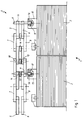
- FIG. 1 shows a schematic diagram of a drive system 1 for a moving walk, which contains the following components: Carriage pallets 2 with associated rollers 3, which roll on rail profiles, not shown, and a transport chain 4, which is composed of inner plates 5.6 and outer plates 7.8, the inner plates 5.6 with the outer plates 7.8 on the one hand over axially longer ones Chain bolts 9 and on the other hand are connected to one another via axially shorter chain bolts 10. Both the axially shorter chain bolts 10 and the axially longer chain bolts 9 are surrounded by only indicated bushings 11, 12, which are provided between the outer plates 7, 8. On the bushes 11, 12, guided rollers 13, 14 are arranged between the inner plates 5, 6, which also roll on rail profiles, not shown.
- the transport chain 4 shown here only on one side can be deflected in the end regions of the moving walk together with the car pallets 2 by means of chain wheels (not shown).
- the carriage pallets 2 are provided in the area of the axially longer chain pins 9 with stub axles 15, into which longitudinal bores 16 are made, which serve to receive the end regions 17 of the axially longer chain pins 11.
- the structural design of the drive system 1, which is only indicated here, is shown in more detail in the following figures.
- FIG. 2 shows a part of the drive system 1 in cross section is the stub axle 15 of the car pallets not shown here, which receives the end region 17 of the axially longer chain pin 9.
- the drive system 1 described here is for example for an indoor area department store escalator used.
- the chain pin 9 is made by a case hardened steel bolt, for example of the alloy 23 CrMoB 33 E, which is formed by an electroless galvanic Process with a nickel layer as wear protection is.
- the chain pin 9 is surrounded by the bush 11, which consists of a case-hardened and tempered steel, e.g. alloy C15E, exists, which is also by a galvanic process without external current is coated with a nickel layer.
- the stud coating and the sleeve coating of solid lubricant for example made of PTFE.
- a bushing 18 Radially between a bushing 18 is arranged on the bushing 11 and the chain pin 9, the homogeneous from a thin-walled fiber-reinforced plastic bushing Structure with embedded solid lubricant components.
- fibers For example, long fiber matrix glass fibers can be used, the socket itself consists of a thermoplastic mixture.
- the chain pin 9 is initial lubricated before the slide bearing is pressed on 18 provided with a lubricating film containing a grease consisting of a Includes polyalfaolefin base oil.
- the drive system 1 also has the on the chain pin 9 pressed outer plates 7,8, which on the Bushes 11 pressed inner tabs 5.6 and the roller 13, the one Rolling bearing 19 includes the bearing inner ring 20 on the associated Bush 11 is pressed.
- the bearing outer ring 21 is of one Injection molded polyamide core 22, which in turn with a tread 23 Polyurethane is coated.
- spacers 24, 25, which are adjacent to the axial Fixation of the bearing 19 also form a sealing point.
- In the area of both End faces 26, 27 of the bushings 11 are each made of a sealing washer 28, 29 PTFE arranged between the inner and outer plates 5.7 and 6.8 respectively.
- the free end 17 is the axially longer one Chain pin 9 rotatably mounted in the bore 16 of the stub axle 15, here also between the free end 17 guided in the bore 16 of the chain pin 9 and the associated peripheral surface 30 of the bore 16 a slide bearing 31 is arranged, which preferably has the same material specification as the slide bearing 18 has.
- the chain pin is also here 9 in the area of its end 17 before being pressed into the slide bearing 31 has been provided with a light lubricating film.
- the plain bearing 31 has a radial shoulder 32 which is between the end face 33 of the Axle stub 15 and the end face 34 of the respective outer plate 8 extends and thus a leadership as well as a sealing function takes over.
- the outer plates 7 are on the outside by means of a snap ring 35 secured against slipping off the chain pin 9.
- FIG 3 shows the part of the drive system 1 that is not between the here axially longer chain pin 9 shown in Figure 2 provided is, namely the axially shorter chain pin 10 in connection with the associated bushings 12 and the rollers 14.
- the structure of this area takes place analogously to that of the axially longer chain pin 9, whereby also same materials are used.
- the plain bearing 36 can be seen as well as the sealing washers 37.38.
- the roller 14 is analogous to the roller 13 from a roller bearing 39, which has a polyamide core 40 and a Has polyurethane treadmill 41.
- the two outer plates 7,8 are there no axial extension of the chain pin 10 is provided by Snap rings 42, 43 secured against slipping off the chain pin 10.
- FIG. 4 shows, as a partial view of a drive system 1, an axially longer one Chain bolt 42, one in operative connection with the stub axle 43 Step not shown here one for outdoor use provided traffic stairs.
- the chain pin 42 also exists here made of a case-hardened steel of 23 CrMoB 33 E alloy, which with wear protection in the form of an electroplated chemical Nickel layer is provided.
- the chain pin 42 is from a bush 44 surrounded by a case hardened tempering steel of the specification C15E, two axially between the chain pin 42 and the bush 44 spaced spaced plain bearings 45, 46 are arranged one behind the other.
- the thin-walled plain bearings 45, 46 consist of a thermoplastic Mixture that is a long fiber matrix with embedded solid lubricant includes.
- these chain bolts are also 42 provided with a lubricating film that, as before already described, contains polyglycol as the base oil.
- a lubricating film that, as before already described, contains polyglycol as the base oil.
- outer plates 47.48 are pressed, while the inner plates 49.50 are pressed onto the socket 44.
- a so-called protective roller 52 on the outer peripheral surface 51 of the bushing 44 applied which is to consist of plastic in this example.
- the protective roller 52 can also be made of steel be, then another between the protective roller 52 and the bush 44 Plain bearing, not shown here, should be provided contains the same or a similar material specification as that Plain bearings 45 and 46.
- cup-shaped trained components 53,54 provided, which, viewed in cross section, each have a radial arm 55, 56 and an axial arm 57, 58.
- the radial legs 55, 56 lie on the end faces 59, 60 of the outer plates 47.48, while the axial legs 57.58 on one another to, i.e. point in the direction of the inner plates 49.50.
- Free space 61, 62 formed is in each case an annular one with a sealing lip 63,64 provided sealing element 65,66 arranged, each on an end portion of the bush 44 is pressed and this in turn supports the associated inner plate 49.50.
- the sealing lip 63.64 of the respective sealing element 65,66 is under residual stress on the associated radial leg 55.56 of component 53.54.
- the free end 67 of the chain pin 42 is analogous to FIG. 2 in a bore 68 of the stub axle 43, with a plain bearing 69 being the same here Material specification like the plain bearing 45, 46 between the peripheral surface 70 of the bore 68 and the end portion 67 of the chain pin 42 are arranged is.
- the sealing element is a self-lubricating bronze ring 71 formed, the end face of the stub 43 provided and on the free end 67 of the chain pin 42 is pressed on.
- roller 73 Except for outer plates 47 is on a shoulder 72 of the chain pin 42, the roller 73 pressed on and axially fixed by means of retaining rings 74.75.
- roller 73 contains a roller bearing 76, which has a casing 77 is provided depending on the loads on the traffic stairs can have a wide variety of materials.
- FIG. 5 shows the part of the drive system 1 outside of the here treads not shown connected axially longer chain bolts 42 according to Figure 4.
- Shown here are the chain pins 78 which take up the outer plates 47, 48 according to FIG. 4.
- the inner straps 49.50 are pressed onto the bushings 44 analogously to FIG. 4.
- Further slide bearings 45, 46 are provided, the protective roller 52, the cup-shaped ones Components 53, 54 and the sealing elements 65 and 66.
- the structural design of the chain pin 78 is with the exception of the missing axial extension here as well as the missing track roller identical to that according to Figure 4.
- the outer plates 47,48 are in view of the missing Components axially fixed by means of snap rings 79.80.
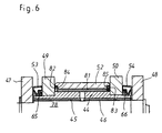
- FIG. 6 shows a partial view of a cross section through a chain link, as shown for example in Figure 5.
- They are recognizable Components chain pin 78, slide bearing 45, 46, bushing 44, protective roller 52, Components 53.54, sealing elements 65.66, outer plates 47.48 and inner plates 49.50.
- Different from FIG. 5 is that between the bushing 44 and the protective roller 52 made of steel in this example is another Slide bearing 81 is provided, since the end face is made of PTFE disc-shaped seals 82.83 is completed.
- the seals 82.83 are inserted in grooves 84.85 of the protective roller 52 and are supported in the area of its free end face on the associated inner plates 49.50 from.
- the slide bearing 81 advantageously has the same material specification like the other plain bearings 45, 46, with initial lubrication here too of the affected components can be made.
Landscapes
- Engineering & Computer Science (AREA)
- General Engineering & Computer Science (AREA)
- Mechanical Engineering (AREA)
- Escalators And Moving Walkways (AREA)
- Chain Conveyers (AREA)
- Devices For Conveying Motion By Means Of Endless Flexible Members (AREA)
- Rolls And Other Rotary Bodies (AREA)
- Moulds For Moulding Plastics Or The Like (AREA)
Description
- die Kettenbolzen sind durch galvanisch beschichtete einsatzgehärtete Stahlbolzen gebildet,
- die Buchsen bestehen aus einem einsatzgehärteten Vergütungsstahl und sind galvanisch beschichtet,
- zwischen den Kettenbolzen und den Buchsen erstreckt sich mindestens ein Gleitlager, das aus einer dünnwandigen, aus thermoplastischen Materialien bestehenden Kunststoffbuchse homogenen Aufbaus gebildet ist.
- Figur 1 -
- teilweise Darstellung eines Antriebssystems für einen Rollsteig
- Figur 2 -
- Querschnitt durch einen axial längeren Kettenbolzen samt Transportkette und Laufrolle für eine Kaufhausrolltreppe
- Figur 3 -
- Querschnitt durch einen axial kürzeren Kettenbolzen als ein weiteres Gelenk der Transportkette gemäß Figur 2
- Figur 4 -
- Querschnitt durch einen axial längeren Kettenbolzen samt Transportkette und Laufrolle für eine Verkehrsrolltreppe
- Figur 5 -
- Querschnitt durch einen axial kürzeren Kettenbolzen als ein weiteres Gelenk der Transportkette gemäß Figur 4
- Figur 6 -
- Querschnitt durch ein Kettenglied mit einem weiteren Gleitlager zwischen Buchse und Schonrolle gemäß Figur 5.
Wagenpaletten 2 mit zugehörigen Laufrollen 3, die auf nicht weiter dargestellten Schienenprofilen abrollen, sowie eine Transportkette 4, die aus Innenlaschen 5,6 und Außenlaschen 7,8 zusammengesetzt ist, wobei die Innenlaschen 5,6 mit den Außenlaschen 7,8 einerseits über axial längere Kettenbolzen 9 und andererseits über axial kürzere Kettenbolzen 10 miteinander verbunden sind. Sowohl die axial kürzeren Kettenbolzen 10 als auch die axial längeren Kettenbolzen 9 sind von hier nur angedeuteten Buchsen 11,12 umgeben, die zwischen den Außenlaschen 7,8 vorgesehen sind. Auf den Buchsen 11,12 sind hierbei zwischen den Innenlaschen 5,6 geführte Laufrollen 13,14 angeordnet, die ebenfalls auf nicht weiter dargestellten Schienenprofilen abrollen. Die hier nur einseitig dargestellte Transportkette 4 ist in den Endbereichen des Rollsteiges zusammen mit den Wagenpaletten 2 mittels nicht dargestellter Kettenräder umlenkbar. Die Wagenpaletten 2 sind im Bereich der axial längeren Kettenbolzen 9 mit Achsstummeln 15 versehen, in die Längsbohrungen 16 eingebracht sind, die zur Aufnahme der Endbereiche 17 der axial längeren Kettenbolzen 11 dienen. Der hier nur angedeutete konstruktive Aufbau des Antriebssystems 1 ist in den folgenden Figuren näher dargestellt.
Claims (40)
- Antriebssystem für die Trittstufen und Wagenpaletten (2) von Rolltreppen und Rollsteigen, bestehend aus jeweils einer seitlich der Trittstufen bzw. Wagenpaletten (2) angeordneten Transportkette (4), die eine Vielzahl von mit Buchsen (11,12,44) zusammenwirkenden Kettenbolzen (9,10,42,78) unterschiedlicher axialer Länge beinhaltet, wobei die axiale längeren, jeweils mit einer Laufrolle (13,73) bestückten Kettenbolzen (9,42) im Bereich der Trittstufen bzw. Wagenpaletten (2) vorgesehen und mit diesen ggf. über weitere Bauelemente verbunden sind, ferner eine Vielzahl von mit den axial kürzeren Kettenbolzen (10,78) und Buchsen (12,44) sowie ggf. ebenfalls mit Laufrollen (14) zusammenwirkenden Laschen (5,6,7,8,47,48,49,50) beinhaltet, die als Innenlaschen (5,6,49,50) drehfest mit den Buchsen (11,12,44) und als Außenlaschen (7,8,47,48) drehfest mit den Kettenbolzen (9,10,42,78) verbunden sind, wobei im Bereich beider Stirnseiten (26,27) der Buchsen (9) Dichtelemente (28,29) vorgesehen sind, gekennzeichnet durch die Kombination folgender Merkmale:die Kettenbolzen (9,10,42,78) sind durch galvanisch beschichtete einsatzgehärtete Stahlbolzen gebildet,die Buchsen (11,12,44) bestehen aus einem einsatzgehärteten Vergütungsstahl und sind galvanisch beschichtet,zwischen den Kettenbolzen (9,10,42,78) und den Buchsen (11,12,44) erstreckt sich mindestens ein Gleitlager (18,36,45,46), das aus einer dünnwandigen, aus thermoplastischen Materialien bestehenden Kunststoffbuchse homogenen Aufbaus gebildet ist.
- Antriebssystem nach Anspruch 1, dadurch gekennzeichnet, daß die Kettenbolzen (9,10,42,78) mit einer Nickelbeschichtung versehen sind.
- Antriebssystem nach den Ansprüchen 1 und 2, dadurch gekennzeichnet, daß die Beschichtung außenstromlos aufgebracht ist.
- Antriebssystem nach den Ansprüchen 1 bis 3, dadurch gekennzeichnet, daß in der Beschichtung Festschmierstoffe, insbesondere PTFE, eingebettet sind.
- Antriebssystem nach den Ansprüchen 1 bis 4, dadurch gekennzeichnet, daß die Buchsen (11,12,44) mit einer Nickelbeschichtung versehen sind.
- Antriebssystem nach den Ansprüchen 1 bis 5, dadurch gekennzeichnet, daß die Beschichtung außenstromlos aufgebracht ist.
- Antriebssystem nach den Ansprüchen 1 bis 6, dadurch gekennzeichnet, daß in der Beschichtung Festschmierstoffe, insbesondere PTFE eingebettet sind.
- Antriebssystem nach den Ansprüchen 1 bis 7, dadurch gekennzeichnet, daß die das Gleitlager (18,36,45,46) bildende Kunststoffbuchse faserverstarkt ist.
- Antriebssystem nach den Ansprüchen 1 bis 8, dadurch gekennzeichnet, daß das Gleitlager (18,36,45,46) eingelagerte Festschmierstoffanteile beinhaltet.
- Antriebssystem nach den Ansprüchen 1 bis 9, dadurch gekennzeichnet, daß das Gleitlager (45,46), in axialer Richtung gesehen, zweigeteilt ausgebildet ist.
- Antriebssystem nach den Ansprüchen 1 bis 10, dadurch gekennzeichnet, daß zumindest zwischen den Kettenbolzen (9,10,42,78) und dem Gleitlager (18,36,45,46) ein Initialschmierstoff vorgesehen ist.
- Antriebssystem nach den Ansprüchen 1 bis 11, dadurch gekennzeichnet, daß der Initialschmierstoff ein Fett ist.
- Antriebssystem nach den Ansprüchen 1 bis 12, dadurch gekennzeichnet, daß das Fett ein Polyalfaolefin-Basisöl beinhaltet.
- Antriebssystem nach den Ansprüchen 1 bis 12, dadurch gekennzeichnet, daß das Fett ein Polyglycol-Basisöl beinhaltet.
- Antriebssystem nach den Ansprüchen 1 bis 14, dadurch gekennzeichnet, daß zwischen den Innenlaschen (5,6) im Bereich der Trittstufen bzw. der Wagenpaletten (2) mit Wälzlagern (19) versehene Laufrollen (13) auf den Buchsen (11) angeordnet sind und die seitliche Abdichtung durch zwischen Innen-(5,6) und Außenlaschen (7,8) vorgesehene scheibenförmige Dichtelemente (28,29) erfolgt, wobei die Dichtelemente (28,29) aus selbstschmierenden Materialien gebildet sind.
- Antriebssystem nach Anspruch 15, dadurch gekennzeichnet, daß die Dichtelemente (28,29) aus PTFE gebildet sind.
- Antriebssystem nach den Ansprüchen 15 und 16, dadurch gekennzeichnet, daß die Dichtelemente (28,29), in Längsrichtung der jeweiligen Transportkette (4) gesehen, auch außerhalb der mit Laufrollen (13) bestückten axial längeren Kettenbolzen (9) zwischen den Innen- (5,6) und Außenlaschen (7,8) auf den jeweiligen axial kürzeren Kettenbolzen (10) aufgepreßt sind.
- Antriebssystem nach den Ansprüchen 15 bis 17, dadurch gekennzeichnet, daß die Laufrollen (12,14,73) lebensdauergeschmierte nach außen abgedichtete Wälzlager (19,39,76) beinhalten.
- Antriebssystem nach den Ansprüchen 15 bis 18, dadurch gekennzeichnet, daß das Wälzlager (19,39) der Laufrollen (13,14) von einem Polyamidkern (22,40) umgeben, insbesondere umspritzt ist, der wiederum mit einer Lauffläche (23,41) aus Polyurethan ummantelt ist.
- Antriebssystem nach den Ansprüchen 15 bis 19, dadurch gekennzeichnet, daß zwischen den Innenlaschen (5,6) und dem Lagerinnenring (20) eine weitere Dichtstelle bildende Distanzstücke (24,25) vorgesehen sind.
- Antriebssystem nach den Ansprüchen 1 bis 14, dadurch gekennzeichnet, daß im Bereich der Trittstufen bzw. der Wagenpaletten (2) außerhalb der Außenlaschen (47) auf den zugehörigen Kettenbolzen (42) Laufrollen (73) vorgesehen sind und die seitliche Abdichtung durch zwischen den Innen- (49,50) und den Außenlaschen (47,48) vorgesehene Dichtelemente (65,66) erfolgt, wobei zwischen den Innen- (49,50) und den Außenlaschen (47,48) im Querschnitt winkelförmige Bauteile (53,54) mit aufeinander zu gerichteten Axialschenkeln (57,58) vorgesehen sind, die jeweils ein in axialer Richtung wirkendes, auf dem jeweiligen Buchsenende aufgepreßtes Dichtelement (65,66), ein Labyrinth bildend, zumindest teilweise axial übergreifen.
- Antriebssystem nach Anspruch 21, dadurch gekennzeichnet, daß das jeweilige Bauteil (53,54) auf den Kettenbolzen (42,78) mit axialem Abstand zu den Stirnflächen der Buchsen (44) aufgepreßt ist und mit seinem Radialschenkel (55,56) an der zugehörigen Außenlaschen (47,48) anliegt.
- Antriebssystem nach den Ansprüchen 21 und 22, dadurch gekennzeichnet, daß das Dichtelement (65,66) eine Dichtlippe (63,64) aufweist, die ggf. unter Eigenspannung an dem Radialschenkel (55,56) des Bauteiles (53,54) anliegt.
- Antriebssystem nach den Ansprüchen 21 bis 23, dadurch gekennzeichnet, daß die Bauteile (53,54) in Verbindung mit den Dichtelementen (65,66), in Längsrichtung der jeweiligen Transportkette (4) gesehen, auch außerhalb der mit Laufrollen (73) bestückten Kettenbolzen (42) zwischen den Innen- (49,50) und den Außenlaschen (47,48) vorgesehen und auf die zugehörigen Kettenbolzen (42,78) aufgepreßt sind.
- Antriebssystem nach den Ansprüchen 21 bis 24, dadurch gekennzeichnet, daß die Bauteile (53,54) aus rostfreiem Stahl bestehen.
- Antriebssystem nach den Ansprüchen 21 bis 24, dadurch gekennzeichnet, daß die Bauteile (53,54) aus Kunststoff bestehen.
- Antriebssystem nach den Ansprüchen 21 bis 26, dadurch gekennzeichnet, daß im Freiraum (61,62) zwischen den Bauteilen (53,54) und den Dichtelementen (65,66) Schmierfett eingebracht ist.
- Antriebssystem nach den Ansprüchen 21 bis 27, dadurch gekennzeichnet, daß die jeweilige Buchse (44) von einer Schonrolle (52) umgeben ist.
- Antriebssystem nach den Ansprüchen 21 bis 28, dadurch gekennzeichnet, daß die Schonrolle (52) aus einem Kunststoff besteht.
- Antriebssystem nach den Ansprüchen 21 bis 28, dadurch gekennzeichnet, daß die Schonrolle (52) aus Stahl besteht und sich über ein Gleitlager (81) auf der zugehörigen Buchse (44) abstützt.
- Antriebssystem nach Anspruch 30, dadurch gekennzeichnet, daß das Gleitlager (81) im Bereich seiner beiden Stirnflächen nach außen jeweils durch eine Dichtung (82,83) abgeschlossen ist.
- Antriebssystem nach den Ansprüchen 30 und 31, dadurch gekennzeichnet, daß die Dichtung (82,83) durch eine Scheibe gebildet ist, die in eine Nut (84,85) im Bereich der jeweiligen Stirnfläche der Schonrolle (52) eingesetzt ist und sich mit ihrer freien Stirnfläche an der zugehörigen Innenlasche (49,50) abstützt.
- Antriebssystem nach den Ansprüchen 30 bis 32, dadurch gekennzeichnet, daß das Gleitlager (81) die gleiche Materialspezifikation wie das zwischen den Kettenbolzen (42,78) und den Buchsen (44) verwendete Gleitlager (45,46) aufweist.
- Antriebssystem nach den Ansprüchen 1 bis 33, dadurch gekennzeichnet, daß die Laschen (5,6,7,8) bei Einsatz der Rolltreppen bzw. Rollsteige im Innenbereich galvanisch verzinkt bzw. mit einem lackartigen Korrosionsschutz versehen sind.
- Antriebssystem nach den Ansprüchen 1 bis 34, dadurch gekennzeichnet, daß die Laschen (47,48,49,50) bei Einsatz der Rolltreppen bzw. Rollsteige im Außenbereich rostschutzbehandelt, insbesondere feuerverzinkt, sind.
- Antriebssystem nach den Ansprüchen 1 bis 35, dadurch gekennzeichnet, daß die mit den Laufrollen (13,73) bestückten axial längeren Kettenbolzen (9,42) in mit jeweils einer Längsbohrung (30,68) versehenen Achsstummeln (15,43) der zugehörigen Trittstufen bzw. Wagenpaletten (2) drehbar gelagert sind.
- Antriebssystem nach Anspruch 36, dadurch gekennzeichnet, daß das Lager (31,69) durch ein initialgeschmiertes Gleitlager gebildet ist.
- Antriebssystem nach den Ansprüchen 36 und 37, dadurch gekennzeichnet, daß das Gleitlager (31,69) die gleiche Materialspezifikation wie die zwischen den Kettenbolzen (9,42) und den Buchsen (11,44) angeordneten Gleitlager (18,45,46) aufweist.
- Antriebssystem nach den Ansprüchen 36 bis 38, dadurch gekennzeichnet, daß das Gleitlager (31) außerhalb der Bohrung (30) einen radial umlaufenden Dichtbereich (32) aufweist, der sich radial zwischen dem freien Ende (33) des Achsstummels (15) und der zugehörigen Außenlasche (8) erstreckt.
- Antriebssystem nach den Ansprüchen 36 bis 39, dadurch gekennzeichnet, daß das Gleitlager (69) nach außen durch ein am freien Ende des Achsstummels (43) angeordnetes Ringelement (71) aus einem selbstschmierenden Material abgedichtet ist.
Applications Claiming Priority (3)
| Application Number | Priority Date | Filing Date | Title |
|---|---|---|---|
| DE4334064 | 1993-10-06 | ||
| DE4334064A DE4334064C3 (de) | 1993-10-06 | 1993-10-06 | Antriebssystem für Rolltreppen und Rollsteige |
| PCT/EP1994/003244 WO1995009802A1 (de) | 1993-10-06 | 1994-09-28 | Antriebssystem für rolltreppen und rollsteige |
Publications (2)
| Publication Number | Publication Date |
|---|---|
| EP0775079A1 EP0775079A1 (de) | 1997-05-28 |
| EP0775079B1 true EP0775079B1 (de) | 1998-06-03 |
Family
ID=6499542
Family Applications (1)
| Application Number | Title | Priority Date | Filing Date |
|---|---|---|---|
| EP94928840A Expired - Lifetime EP0775079B1 (de) | 1993-10-06 | 1994-09-28 | Antriebssystem für rolltreppen und rollsteige |
Country Status (14)
| Country | Link |
|---|---|
| US (1) | US5785166A (de) |
| EP (1) | EP0775079B1 (de) |
| JP (1) | JP2860167B2 (de) |
| KR (1) | KR100319004B1 (de) |
| CN (1) | CN1037084C (de) |
| AT (1) | ATE166855T1 (de) |
| BR (1) | BR9406168A (de) |
| CZ (1) | CZ290688B6 (de) |
| DE (2) | DE4334064C3 (de) |
| ES (1) | ES2120071T3 (de) |
| HU (1) | HU217287B (de) |
| RU (1) | RU2141925C1 (de) |
| SK (1) | SK280663B6 (de) |
| WO (1) | WO1995009802A1 (de) |
Cited By (1)
| Publication number | Priority date | Publication date | Assignee | Title |
|---|---|---|---|---|
| DE102018113882A1 (de) | 2018-06-11 | 2019-12-12 | Ketten-Wulf Betriebs-Gmbh | Gelenkkette |
Families Citing this family (43)
| Publication number | Priority date | Publication date | Assignee | Title |
|---|---|---|---|---|
| DE29514700U1 (de) * | 1995-09-13 | 1995-11-02 | Erich Wulf Und Sohn Gmbh & Co. Kg, 59889 Eslohe | Rollenkette (Gelenkkette) |
| DE19548662C1 (de) * | 1995-12-18 | 1997-04-30 | Mannesmann Ag | Transportzahnkette |
| US5806653A (en) * | 1995-12-19 | 1998-09-15 | Otis Elevator Company | Roller assembly for a passenger conveyor step chain |
| JPH11286317A (ja) * | 1998-03-31 | 1999-10-19 | Tsubakimoto Chain Co | 増速アキュムレートコンベヤチェーン |
| FR2778957B1 (fr) * | 1998-05-19 | 2000-07-21 | Mediterranee Const Ind | Chaine mecanique destinee notamment a l'entrainement d'escaliers mecaniques et de trottoirs roulants |
| DE10124131A1 (de) * | 2001-05-17 | 2002-11-28 | Winklhofer & Soehne Gmbh | Fördersystem |
| DE20301358U1 (de) * | 2003-01-29 | 2003-06-05 | Thyssen Fahrtreppen GmbH, 22113 Hamburg | Fahrtreppe oder Fahrsteig |
| JP4368178B2 (ja) * | 2003-10-10 | 2009-11-18 | 東芝エレベータ株式会社 | 乗客コンベア |
| DE10359922A1 (de) * | 2003-12-18 | 2005-08-04 | Horst Weidner Gmbh | Rollenkette |
| FI116218B (fi) * | 2004-02-02 | 2005-10-14 | Kone Corp | Liukukäytävän tai vastaavan paletin kytkentäjärjestely |
| RU2422353C9 (ru) * | 2004-07-08 | 2011-09-27 | Отис Элевейтэ Кампэни | Ступень пассажирского транспортера, пассажирский транспортер и способ его звукоизоляции |
| JP2006145005A (ja) * | 2004-11-24 | 2006-06-08 | Tsubakimoto Chain Co | 耐食性チェーン |
| JP2007230673A (ja) * | 2006-02-27 | 2007-09-13 | Toshiba Elevator Co Ltd | マンコンベア |
| JP2007298056A (ja) * | 2006-04-27 | 2007-11-15 | Tsubakimoto Chain Co | 防食性ローラチェーン |
| DE102006030212A1 (de) * | 2006-06-30 | 2008-01-03 | Magdeburger Förderanlagen und Baumaschinen GmbH | Kettenförderer für Schüttgut |
| ES2573674T3 (es) * | 2006-12-21 | 2016-06-09 | Inventio Ag | Sistema de accionamiento para un dispositivo de traslación con cadena deslizante |
| JP4361117B2 (ja) * | 2008-01-25 | 2009-11-11 | 株式会社椿本チエイン | サイドローラ付きコンベヤチェーン |
| DE102008002455A1 (de) | 2008-06-16 | 2009-12-17 | Kone Corp. | Antriebskette mit Gleitbuchse |
| US8631086B2 (en) * | 2008-09-30 | 2014-01-14 | International Business Machines Corporation | Preventing messaging queue deadlocks in a DMA environment |
| US8671172B2 (en) * | 2009-07-09 | 2014-03-11 | International Business Machines Corporation | Network device configuration |
| DE102009033819B4 (de) * | 2009-07-18 | 2013-01-17 | Kone Corp. | Einrichtung zum Verbinden einer Kette mit einer Stufe oder einer Palette einer Personenfördereinrichtung |
| CN101734543B (zh) * | 2009-12-18 | 2012-01-25 | 西子奥的斯电梯有限公司 | 一种自动扶梯扶手带运转装置 |
| DE112010005926B4 (de) | 2010-10-08 | 2016-11-17 | Otis Elevator Company | Personenbeförderungsvorrichtung mit bewegbaren seitlichen Tafelelementen |
| JP2014514227A (ja) | 2011-05-09 | 2014-06-19 | オーチス エレベータ カンパニー | 軸受アッセンブリ用のシールアッセンブリ |
| CN102322499A (zh) * | 2011-06-20 | 2012-01-18 | 苏州市申龙电梯有限公司 | 重载梯级链 |
| CN102303807A (zh) * | 2011-08-30 | 2012-01-04 | 昆山通祐电梯有限公司 | 梯级链轮传动机构 |
| JP5468111B2 (ja) * | 2012-07-05 | 2014-04-09 | 株式会社椿本チエイン | 走行ローラ付きコンベヤチェーン |
| JP2016090022A (ja) * | 2014-11-11 | 2016-05-23 | 株式会社椿本チエイン | チェーン |
| DE102015212031A1 (de) * | 2015-06-29 | 2016-12-29 | Thyssenkrupp Ag | Stufenkette für Fahrtreppen sowie Personenfördervorrichtung mit einer solchen Stufenkette |
| CN105317929A (zh) * | 2015-11-27 | 2016-02-10 | 苏州环球集团科技股份有限公司 | 免润滑梯级链 |
| EP3231760A1 (de) | 2016-04-15 | 2017-10-18 | Otis Elevator Company | Befestigungsmodule und paletten für eine palettentransportvorrichtung |
| EP3231761B1 (de) | 2016-04-15 | 2019-02-20 | Otis Elevator Company | Plattenförderer |
| CN105731231B (zh) * | 2016-04-22 | 2017-07-21 | 浙江长盛塑料轴承技术有限公司 | 一种用于扶梯的回转链 |
| EP3257804B1 (de) | 2016-06-15 | 2023-09-27 | Otis Elevator Company | Riemengetriebene personenförderanlage |
| JP6581549B2 (ja) * | 2016-08-03 | 2019-09-25 | 株式会社日立製作所 | 乗客コンベア |
| DE202016105851U1 (de) * | 2016-10-19 | 2018-01-22 | Siempelkamp Maschinen- Und Anlagenbau Gmbh | Rollstabkette und kontinuierliche Presse |
| CN106629365B (zh) * | 2017-03-07 | 2018-06-19 | 苏州环球科技股份有限公司 | 一种不锈钢梯级链 |
| US10520029B2 (en) * | 2017-04-19 | 2019-12-31 | Seiko Instruments Inc. | Structure with thermoplastic elastomer enveloping layer, bearing, and drive module |
| CN107161608B (zh) * | 2017-06-05 | 2019-03-01 | 中国矿业大学 | 一种可适用于不平整采煤工作面的刮板结构 |
| CN107600949A (zh) * | 2017-09-21 | 2018-01-19 | 方乐 | 一种链板式输送机滚轮轴承系统 |
| DE102017220152B4 (de) | 2017-11-13 | 2021-01-21 | Fraunhofer-Gesellschaft zur Förderung der angewandten Forschung e.V. | Antriebsanordnung für ein Zweirad |
| WO2022126553A1 (zh) * | 2020-12-17 | 2022-06-23 | 苏州挚略知识产权运营有限公司 | 一种具有自润滑功能的梯级链 |
| RU208316U1 (ru) * | 2021-07-08 | 2021-12-13 | Федеральное государственное бюджетное образовательное учреждение высшего образования "Донской государственный аграрный университет" (ФГБОУ ВО Донской ГАУ) | Приводная пластинчатая цепь |
Family Cites Families (16)
| Publication number | Priority date | Publication date | Assignee | Title |
|---|---|---|---|---|
| US2145343A (en) * | 1936-08-07 | 1939-01-31 | Westinghouse Air Brake Co | Moving stair roller |
| DE1869061U (de) * | 1961-06-23 | 1963-03-21 | Menck & Hambrock Gmbh | Elektromotor, insbesondere fuer vibrationsgeraete. |
| DE1863061U (de) * | 1962-10-15 | 1962-11-29 | Cie Des Transmissions Mechaniq | Gelenkverbindung fuer uebertragungsketten. |
| US3815959A (en) * | 1972-08-08 | 1974-06-11 | M Hill | Industrial roller or wheel |
| JPS5135664B2 (de) * | 1973-02-13 | 1976-10-04 | ||
| US4232783A (en) * | 1979-03-19 | 1980-11-11 | Westinghouse Electric Corp. | Step link for transportation apparatus |
| US4361220A (en) * | 1981-02-25 | 1982-11-30 | Westinghouse Electric Corp. | Drive chain |
| CH655482B (de) * | 1982-05-06 | 1986-04-30 | ||
| BR8402225A (pt) * | 1983-05-12 | 1984-12-18 | Westinghouse Electric Corp | Correia transportadora articulada |
| DE3412350C2 (de) * | 1984-04-03 | 1987-01-02 | O & K Orenstein & Koppel Ag, 1000 Berlin | Rollen innerhalb der Transportkette einer Personenfördereinrichtung |
| JP2655409B2 (ja) * | 1988-01-12 | 1997-09-17 | 日本電気株式会社 | マイクロ波着陸誘導装置 |
| DE3808912A1 (de) * | 1988-03-17 | 1989-10-05 | Walter Hunger | Gleitlagerbuchse |
| US5072821A (en) * | 1990-12-07 | 1991-12-17 | Otis Elevator Company | Escalator/people mover bearing |
| US5137135A (en) * | 1991-03-13 | 1992-08-11 | Otis Elevator Company | Escalator step chain roller |
| US5219060A (en) * | 1991-05-24 | 1993-06-15 | Otis Elevator Company | Step axle for escalator |
| DE4241758C2 (de) * | 1992-12-11 | 1997-05-28 | Wulf Erich & Sohn | Büchsenförderkette |
-
1993
- 1993-10-06 DE DE4334064A patent/DE4334064C3/de not_active Expired - Lifetime
-
1994
- 1994-09-28 AT AT94928840T patent/ATE166855T1/de active
- 1994-09-28 DE DE59406153T patent/DE59406153D1/de not_active Expired - Lifetime
- 1994-09-28 SK SK1103-95A patent/SK280663B6/sk not_active IP Right Cessation
- 1994-09-28 BR BR9406168A patent/BR9406168A/pt not_active IP Right Cessation
- 1994-09-28 HU HU9600896A patent/HU217287B/hu not_active IP Right Cessation
- 1994-09-28 RU RU96108832A patent/RU2141925C1/ru not_active IP Right Cessation
- 1994-09-28 JP JP7510599A patent/JP2860167B2/ja not_active Expired - Lifetime
- 1994-09-28 ES ES94928840T patent/ES2120071T3/es not_active Expired - Lifetime
- 1994-09-28 US US08/637,788 patent/US5785166A/en not_active Expired - Lifetime
- 1994-09-28 WO PCT/EP1994/003244 patent/WO1995009802A1/de not_active Ceased
- 1994-09-28 CN CN94190761A patent/CN1037084C/zh not_active Expired - Lifetime
- 1994-09-28 CZ CZ19951621A patent/CZ290688B6/cs not_active IP Right Cessation
- 1994-09-28 EP EP94928840A patent/EP0775079B1/de not_active Expired - Lifetime
- 1994-09-28 KR KR1019950702893A patent/KR100319004B1/ko not_active Expired - Lifetime
Cited By (1)
| Publication number | Priority date | Publication date | Assignee | Title |
|---|---|---|---|---|
| DE102018113882A1 (de) | 2018-06-11 | 2019-12-12 | Ketten-Wulf Betriebs-Gmbh | Gelenkkette |
Also Published As
| Publication number | Publication date |
|---|---|
| CN1115177A (zh) | 1996-01-17 |
| HU217287B (hu) | 1999-12-28 |
| ATE166855T1 (de) | 1998-06-15 |
| EP0775079A1 (de) | 1997-05-28 |
| DE4334064C3 (de) | 1999-07-15 |
| CZ162195A3 (en) | 1996-02-14 |
| WO1995009802A1 (de) | 1995-04-13 |
| KR960702814A (ko) | 1996-05-23 |
| HU9600896D0 (en) | 1996-05-28 |
| CN1037084C (zh) | 1998-01-21 |
| RU2141925C1 (ru) | 1999-11-27 |
| BR9406168A (pt) | 1996-01-09 |
| DE4334064A1 (de) | 1995-04-13 |
| US5785166A (en) | 1998-07-28 |
| CZ290688B6 (cs) | 2002-09-11 |
| SK110395A3 (en) | 1996-05-08 |
| KR100319004B1 (ko) | 2002-11-29 |
| DE4334064C2 (de) | 1996-03-07 |
| JPH09503193A (ja) | 1997-03-31 |
| HUT74994A (en) | 1997-03-28 |
| DE59406153D1 (de) | 1998-07-09 |
| ES2120071T3 (es) | 1998-10-16 |
| JP2860167B2 (ja) | 1999-02-24 |
| SK280663B6 (sk) | 2000-05-16 |
Similar Documents
| Publication | Publication Date | Title |
|---|---|---|
| DE4334064C2 (de) | Antriebssystem für Rolltreppen und Rollsteige | |
| DE60132560T2 (de) | Raupenkette | |
| EP0485696B1 (de) | Elastisches Gleitlager | |
| DE69517368T3 (de) | Kompaktlager und versteifter Lagerzapfen | |
| DE4037966C2 (de) | Elastisches Gleitlager für Fahrwerksteile | |
| DE19839430C2 (de) | Radialkolbenpumpe | |
| DE19547008B4 (de) | Laufwerkrollenanordnung | |
| DE19531132B4 (de) | Verfahren zum Herstellen von Führungsrollen | |
| DE3227736A1 (de) | Laufkatze | |
| DE102017107005B3 (de) | Abgedichtetes Wälzlager | |
| DE19944723B4 (de) | Radlagervorrichtung | |
| DE2448180A1 (de) | Lager fuer foerdererwalzen oder -rollen o. dgl. | |
| WO2009153105A1 (de) | Antriebskette mit gleitbuchse | |
| DE2603250A1 (de) | Dichtanordnung fuer ein axiallager | |
| DE19653188A1 (de) | Rollenanordnung für eine Fahrgastbeförderer-Stufenkette | |
| DE19915975B4 (de) | Wälzlager | |
| DE102010008650A1 (de) | Lagerring für ein Wälzlager | |
| DE9315150U1 (de) | Antriebssystem für Rolltreppen und Rollsteige | |
| EP2456706B1 (de) | Einrichtung zum verbinden einer kette mit einer stufe oder einer palette einer personenfördereinrichtung | |
| DE4123808A1 (de) | Rollenlager | |
| DE19750113B4 (de) | Wälzlager | |
| EP4284746B1 (de) | Fahrtreppe oder eines fahrsteiges mit einem stellring | |
| DE2415903A1 (de) | Waelzlager | |
| DE19959817A1 (de) | Baumaschine, insbesondere Planierraupe | |
| DE3701886A1 (de) | Dichtungsanordnung fuer ein waelzlager einer elastischen lagerung |
Legal Events
| Date | Code | Title | Description |
|---|---|---|---|
| PUAI | Public reference made under article 153(3) epc to a published international application that has entered the european phase |
Free format text: ORIGINAL CODE: 0009012 |
|
| 17P | Request for examination filed |
Effective date: 19950505 |
|
| AK | Designated contracting states |
Kind code of ref document: A1 Designated state(s): AT BE CH DE ES FR GB IT LI NL SE |
|
| GRAG | Despatch of communication of intention to grant |
Free format text: ORIGINAL CODE: EPIDOS AGRA |
|
| 17Q | First examination report despatched |
Effective date: 19970820 |
|
| GRAG | Despatch of communication of intention to grant |
Free format text: ORIGINAL CODE: EPIDOS AGRA |
|
| GRAH | Despatch of communication of intention to grant a patent |
Free format text: ORIGINAL CODE: EPIDOS IGRA |
|
| GRAH | Despatch of communication of intention to grant a patent |
Free format text: ORIGINAL CODE: EPIDOS IGRA |
|
| GRAA | (expected) grant |
Free format text: ORIGINAL CODE: 0009210 |
|
| AK | Designated contracting states |
Kind code of ref document: B1 Designated state(s): AT BE CH DE ES FR GB IT LI NL SE |
|
| REF | Corresponds to: |
Ref document number: 166855 Country of ref document: AT Date of ref document: 19980615 Kind code of ref document: T |
|
| REG | Reference to a national code |
Ref country code: CH Ref legal event code: EP |
|
| REF | Corresponds to: |
Ref document number: 59406153 Country of ref document: DE Date of ref document: 19980709 |
|
| ITF | It: translation for a ep patent filed | ||
| REG | Reference to a national code |
Ref country code: CH Ref legal event code: NV Representative=s name: DIPL.-ING. ETH H. R. WERFFELI PATENTANWALT |
|
| GBT | Gb: translation of ep patent filed (gb section 77(6)(a)/1977) |
Effective date: 19980724 |
|
| RAP2 | Party data changed (patent owner data changed or rights of a patent transferred) |
Owner name: KETTEN WULF GMBH, GELENKKETTEN- UND KETTENRAEDERF Owner name: O & K ROLLTREPPEN GMBH & CO KG |
|
| NLT2 | Nl: modifications (of names), taken from the european patent patent bulletin |
Owner name: O & K ROLLTREPPEN GMBH & CO KG EN KETTEN WULF GMBH |
|
| REG | Reference to a national code |
Ref country code: ES Ref legal event code: FG2A Ref document number: 2120071 Country of ref document: ES Kind code of ref document: T3 |
|
| ET | Fr: translation filed | ||
| NLT1 | Nl: modifications of names registered in virtue of documents presented to the patent office pursuant to art. 16 a, paragraph 1 |
Owner name: O&K ROLTREPPEN GMBH & CO. KG;KETTEN WULF GMBH, GEL |
|
| BECA | Be: change of holder's address |
Free format text: 980603 *O & K ROLLTREPPEN G.M.B.H. & CO. K.G.:NIERENHOFER STRASSE 10, 45525 HATTINGEN/RUHR |
|
| BECN | Be: change of holder's name |
Effective date: 19980603 |
|
| PLBQ | Unpublished change to opponent data |
Free format text: ORIGINAL CODE: EPIDOS OPPO |
|
| PLBI | Opposition filed |
Free format text: ORIGINAL CODE: 0009260 |
|
| 26 | Opposition filed |
Opponent name: REGINA INDUSTRIA S.P.A Effective date: 19990303 Opponent name: OTIS ELEVATOR COMPANY Effective date: 19990303 |
|
| PLBF | Reply of patent proprietor to notice(s) of opposition |
Free format text: ORIGINAL CODE: EPIDOS OBSO |
|
| NLR1 | Nl: opposition has been filed with the epo |
Opponent name: REGINA INDUSTRIA S.P.A Opponent name: OTIS ELEVATOR COMPANY |
|
| PLBF | Reply of patent proprietor to notice(s) of opposition |
Free format text: ORIGINAL CODE: EPIDOS OBSO |
|
| REG | Reference to a national code |
Ref country code: GB Ref legal event code: 732E |
|
| REG | Reference to a national code |
Ref country code: GB Ref legal event code: IF02 |
|
| PLBO | Opposition rejected |
Free format text: ORIGINAL CODE: EPIDOS REJO |
|
| PLBN | Opposition rejected |
Free format text: ORIGINAL CODE: 0009273 |
|
| STAA | Information on the status of an ep patent application or granted ep patent |
Free format text: STATUS: OPPOSITION REJECTED |
|
| 27O | Opposition rejected |
Effective date: 20020115 |
|
| NLR2 | Nl: decision of opposition | ||
| PGFP | Annual fee paid to national office [announced via postgrant information from national office to epo] |
Ref country code: BE Payment date: 20091023 Year of fee payment: 16 |
|
| BERE | Be: lapsed |
Owner name: *KETTEN WULF G.M.B.H. GELENKETTEN- UND KETTENRADER Effective date: 20100930 Owner name: *KONE CORP. Effective date: 20100930 |
|
| PG25 | Lapsed in a contracting state [announced via postgrant information from national office to epo] |
Ref country code: BE Free format text: LAPSE BECAUSE OF NON-PAYMENT OF DUE FEES Effective date: 20100930 |
|
| PGFP | Annual fee paid to national office [announced via postgrant information from national office to epo] |
Ref country code: SE Payment date: 20120919 Year of fee payment: 19 |
|
| PGFP | Annual fee paid to national office [announced via postgrant information from national office to epo] |
Ref country code: NL Payment date: 20120920 Year of fee payment: 19 |
|
| PGFP | Annual fee paid to national office [announced via postgrant information from national office to epo] |
Ref country code: IT Payment date: 20120927 Year of fee payment: 19 |
|
| PGFP | Annual fee paid to national office [announced via postgrant information from national office to epo] |
Ref country code: ES Payment date: 20130918 Year of fee payment: 20 Ref country code: CH Payment date: 20130919 Year of fee payment: 20 Ref country code: AT Payment date: 20130911 Year of fee payment: 20 Ref country code: DE Payment date: 20130919 Year of fee payment: 20 |
|
| PGFP | Annual fee paid to national office [announced via postgrant information from national office to epo] |
Ref country code: GB Payment date: 20130919 Year of fee payment: 20 Ref country code: FR Payment date: 20130919 Year of fee payment: 20 |
|
| REG | Reference to a national code |
Ref country code: NL Ref legal event code: V1 Effective date: 20140401 |
|
| REG | Reference to a national code |
Ref country code: SE Ref legal event code: EUG |
|
| PG25 | Lapsed in a contracting state [announced via postgrant information from national office to epo] |
Ref country code: SE Free format text: LAPSE BECAUSE OF NON-PAYMENT OF DUE FEES Effective date: 20130929 |
|
| PG25 | Lapsed in a contracting state [announced via postgrant information from national office to epo] |
Ref country code: IT Free format text: LAPSE BECAUSE OF NON-PAYMENT OF DUE FEES Effective date: 20130928 Ref country code: NL Free format text: LAPSE BECAUSE OF NON-PAYMENT OF DUE FEES Effective date: 20140401 |
|
| REG | Reference to a national code |
Ref country code: DE Ref legal event code: R071 Ref document number: 59406153 Country of ref document: DE |
|
| REG | Reference to a national code |
Ref country code: DE Ref legal event code: R071 Ref document number: 59406153 Country of ref document: DE Ref country code: CH Ref legal event code: PL |
|
| REG | Reference to a national code |
Ref country code: GB Ref legal event code: PE20 Expiry date: 20140927 |
|
| PG25 | Lapsed in a contracting state [announced via postgrant information from national office to epo] |
Ref country code: DE Free format text: LAPSE BECAUSE OF EXPIRATION OF PROTECTION Effective date: 20140930 |
|
| REG | Reference to a national code |
Ref country code: AT Ref legal event code: MK07 Ref document number: 166855 Country of ref document: AT Kind code of ref document: T Effective date: 20140928 |
|
| PG25 | Lapsed in a contracting state [announced via postgrant information from national office to epo] |
Ref country code: GB Free format text: LAPSE BECAUSE OF EXPIRATION OF PROTECTION Effective date: 20140927 |
|
| REG | Reference to a national code |
Ref country code: ES Ref legal event code: FD2A Effective date: 20150108 |
|
| PG25 | Lapsed in a contracting state [announced via postgrant information from national office to epo] |
Ref country code: ES Free format text: LAPSE BECAUSE OF EXPIRATION OF PROTECTION Effective date: 20140929 |