EP0774054B1 - Combatting air pollution - Google Patents
Combatting air pollution Download PDFInfo
- Publication number
- EP0774054B1 EP0774054B1 EP96919964A EP96919964A EP0774054B1 EP 0774054 B1 EP0774054 B1 EP 0774054B1 EP 96919964 A EP96919964 A EP 96919964A EP 96919964 A EP96919964 A EP 96919964A EP 0774054 B1 EP0774054 B1 EP 0774054B1
- Authority
- EP
- European Patent Office
- Prior art keywords
- oxidation catalyst
- catalyst
- hydrocarbon
- temperature
- engine
- Prior art date
- Legal status (The legal status is an assumption and is not a legal conclusion. Google has not performed a legal analysis and makes no representation as to the accuracy of the status listed.)
- Expired - Lifetime
Links
Images


Classifications
-
- B—PERFORMING OPERATIONS; TRANSPORTING
- B01—PHYSICAL OR CHEMICAL PROCESSES OR APPARATUS IN GENERAL
- B01D—SEPARATION
- B01D53/00—Separation of gases or vapours; Recovering vapours of volatile solvents from gases; Chemical or biological purification of waste gases, e.g. engine exhaust gases, smoke, fumes, flue gases, aerosols
- B01D53/34—Chemical or biological purification of waste gases
- B01D53/92—Chemical or biological purification of waste gases of engine exhaust gases
- B01D53/94—Chemical or biological purification of waste gases of engine exhaust gases by catalytic processes
- B01D53/9481—Catalyst preceded by an adsorption device without catalytic function for temporary storage of contaminants, e.g. during cold start
-
- B—PERFORMING OPERATIONS; TRANSPORTING
- B01—PHYSICAL OR CHEMICAL PROCESSES OR APPARATUS IN GENERAL
- B01D—SEPARATION
- B01D53/00—Separation of gases or vapours; Recovering vapours of volatile solvents from gases; Chemical or biological purification of waste gases, e.g. engine exhaust gases, smoke, fumes, flue gases, aerosols
- B01D53/26—Drying gases or vapours
- B01D53/261—Drying gases or vapours by adsorption
-
- B—PERFORMING OPERATIONS; TRANSPORTING
- B01—PHYSICAL OR CHEMICAL PROCESSES OR APPARATUS IN GENERAL
- B01D—SEPARATION
- B01D53/00—Separation of gases or vapours; Recovering vapours of volatile solvents from gases; Chemical or biological purification of waste gases, e.g. engine exhaust gases, smoke, fumes, flue gases, aerosols
- B01D53/34—Chemical or biological purification of waste gases
- B01D53/92—Chemical or biological purification of waste gases of engine exhaust gases
- B01D53/94—Chemical or biological purification of waste gases of engine exhaust gases by catalytic processes
- B01D53/944—Simultaneously removing carbon monoxide, hydrocarbons or carbon making use of oxidation catalysts
-
- F—MECHANICAL ENGINEERING; LIGHTING; HEATING; WEAPONS; BLASTING
- F01—MACHINES OR ENGINES IN GENERAL; ENGINE PLANTS IN GENERAL; STEAM ENGINES
- F01N—GAS-FLOW SILENCERS OR EXHAUST APPARATUS FOR MACHINES OR ENGINES IN GENERAL; GAS-FLOW SILENCERS OR EXHAUST APPARATUS FOR INTERNAL-COMBUSTION ENGINES
- F01N13/00—Exhaust or silencing apparatus characterised by constructional features
- F01N13/009—Exhaust or silencing apparatus characterised by constructional features having two or more separate purifying devices arranged in series
-
- F—MECHANICAL ENGINEERING; LIGHTING; HEATING; WEAPONS; BLASTING
- F01—MACHINES OR ENGINES IN GENERAL; ENGINE PLANTS IN GENERAL; STEAM ENGINES
- F01N—GAS-FLOW SILENCERS OR EXHAUST APPARATUS FOR MACHINES OR ENGINES IN GENERAL; GAS-FLOW SILENCERS OR EXHAUST APPARATUS FOR INTERNAL-COMBUSTION ENGINES
- F01N3/00—Exhaust or silencing apparatus having means for purifying, rendering innocuous, or otherwise treating exhaust
- F01N3/08—Exhaust or silencing apparatus having means for purifying, rendering innocuous, or otherwise treating exhaust for rendering innocuous
- F01N3/0807—Exhaust or silencing apparatus having means for purifying, rendering innocuous, or otherwise treating exhaust for rendering innocuous by using absorbents or adsorbents
- F01N3/0814—Exhaust or silencing apparatus having means for purifying, rendering innocuous, or otherwise treating exhaust for rendering innocuous by using absorbents or adsorbents combined with catalytic converters, e.g. NOx absorption/storage reduction catalysts
-
- F—MECHANICAL ENGINEERING; LIGHTING; HEATING; WEAPONS; BLASTING
- F01—MACHINES OR ENGINES IN GENERAL; ENGINE PLANTS IN GENERAL; STEAM ENGINES
- F01N—GAS-FLOW SILENCERS OR EXHAUST APPARATUS FOR MACHINES OR ENGINES IN GENERAL; GAS-FLOW SILENCERS OR EXHAUST APPARATUS FOR INTERNAL-COMBUSTION ENGINES
- F01N3/00—Exhaust or silencing apparatus having means for purifying, rendering innocuous, or otherwise treating exhaust
- F01N3/08—Exhaust or silencing apparatus having means for purifying, rendering innocuous, or otherwise treating exhaust for rendering innocuous
- F01N3/0807—Exhaust or silencing apparatus having means for purifying, rendering innocuous, or otherwise treating exhaust for rendering innocuous by using absorbents or adsorbents
- F01N3/0828—Exhaust or silencing apparatus having means for purifying, rendering innocuous, or otherwise treating exhaust for rendering innocuous by using absorbents or adsorbents characterised by the absorbed or adsorbed substances
- F01N3/0835—Hydrocarbons
-
- F—MECHANICAL ENGINEERING; LIGHTING; HEATING; WEAPONS; BLASTING
- F01—MACHINES OR ENGINES IN GENERAL; ENGINE PLANTS IN GENERAL; STEAM ENGINES
- F01N—GAS-FLOW SILENCERS OR EXHAUST APPARATUS FOR MACHINES OR ENGINES IN GENERAL; GAS-FLOW SILENCERS OR EXHAUST APPARATUS FOR INTERNAL-COMBUSTION ENGINES
- F01N3/00—Exhaust or silencing apparatus having means for purifying, rendering innocuous, or otherwise treating exhaust
- F01N3/08—Exhaust or silencing apparatus having means for purifying, rendering innocuous, or otherwise treating exhaust for rendering innocuous
- F01N3/10—Exhaust or silencing apparatus having means for purifying, rendering innocuous, or otherwise treating exhaust for rendering innocuous by thermal or catalytic conversion of noxious components of exhaust
- F01N3/18—Exhaust or silencing apparatus having means for purifying, rendering innocuous, or otherwise treating exhaust for rendering innocuous by thermal or catalytic conversion of noxious components of exhaust characterised by methods of operation; Control
- F01N3/20—Exhaust or silencing apparatus having means for purifying, rendering innocuous, or otherwise treating exhaust for rendering innocuous by thermal or catalytic conversion of noxious components of exhaust characterised by methods of operation; Control specially adapted for catalytic conversion
-
- B—PERFORMING OPERATIONS; TRANSPORTING
- B01—PHYSICAL OR CHEMICAL PROCESSES OR APPARATUS IN GENERAL
- B01D—SEPARATION
- B01D2253/00—Adsorbents used in seperation treatment of gases and vapours
- B01D2253/10—Inorganic adsorbents
- B01D2253/106—Silica or silicates
- B01D2253/108—Zeolites
-
- F—MECHANICAL ENGINEERING; LIGHTING; HEATING; WEAPONS; BLASTING
- F01—MACHINES OR ENGINES IN GENERAL; ENGINE PLANTS IN GENERAL; STEAM ENGINES
- F01N—GAS-FLOW SILENCERS OR EXHAUST APPARATUS FOR MACHINES OR ENGINES IN GENERAL; GAS-FLOW SILENCERS OR EXHAUST APPARATUS FOR INTERNAL-COMBUSTION ENGINES
- F01N2250/00—Combinations of different methods of purification
- F01N2250/12—Combinations of different methods of purification absorption or adsorption, and catalytic conversion
-
- F—MECHANICAL ENGINEERING; LIGHTING; HEATING; WEAPONS; BLASTING
- F01—MACHINES OR ENGINES IN GENERAL; ENGINE PLANTS IN GENERAL; STEAM ENGINES
- F01N—GAS-FLOW SILENCERS OR EXHAUST APPARATUS FOR MACHINES OR ENGINES IN GENERAL; GAS-FLOW SILENCERS OR EXHAUST APPARATUS FOR INTERNAL-COMBUSTION ENGINES
- F01N2340/00—Dimensional characteristics of the exhaust system, e.g. length, diameter or volume of the exhaust apparatus; Spatial arrangements of exhaust apparatuses
- F01N2340/02—Distance of the exhaust apparatus to the engine or between two exhaust apparatuses
-
- F—MECHANICAL ENGINEERING; LIGHTING; HEATING; WEAPONS; BLASTING
- F01—MACHINES OR ENGINES IN GENERAL; ENGINE PLANTS IN GENERAL; STEAM ENGINES
- F01N—GAS-FLOW SILENCERS OR EXHAUST APPARATUS FOR MACHINES OR ENGINES IN GENERAL; GAS-FLOW SILENCERS OR EXHAUST APPARATUS FOR INTERNAL-COMBUSTION ENGINES
- F01N3/00—Exhaust or silencing apparatus having means for purifying, rendering innocuous, or otherwise treating exhaust
- F01N3/08—Exhaust or silencing apparatus having means for purifying, rendering innocuous, or otherwise treating exhaust for rendering innocuous
- F01N3/10—Exhaust or silencing apparatus having means for purifying, rendering innocuous, or otherwise treating exhaust for rendering innocuous by thermal or catalytic conversion of noxious components of exhaust
- F01N3/24—Exhaust or silencing apparatus having means for purifying, rendering innocuous, or otherwise treating exhaust for rendering innocuous by thermal or catalytic conversion of noxious components of exhaust characterised by constructional aspects of converting apparatus
- F01N3/30—Arrangements for supply of additional air
-
- F—MECHANICAL ENGINEERING; LIGHTING; HEATING; WEAPONS; BLASTING
- F02—COMBUSTION ENGINES; HOT-GAS OR COMBUSTION-PRODUCT ENGINE PLANTS
- F02B—INTERNAL-COMBUSTION PISTON ENGINES; COMBUSTION ENGINES IN GENERAL
- F02B1/00—Engines characterised by fuel-air mixture compression
- F02B1/02—Engines characterised by fuel-air mixture compression with positive ignition
- F02B1/04—Engines characterised by fuel-air mixture compression with positive ignition with fuel-air mixture admission into cylinder
-
- Y—GENERAL TAGGING OF NEW TECHNOLOGICAL DEVELOPMENTS; GENERAL TAGGING OF CROSS-SECTIONAL TECHNOLOGIES SPANNING OVER SEVERAL SECTIONS OF THE IPC; TECHNICAL SUBJECTS COVERED BY FORMER USPC CROSS-REFERENCE ART COLLECTIONS [XRACs] AND DIGESTS
- Y02—TECHNOLOGIES OR APPLICATIONS FOR MITIGATION OR ADAPTATION AGAINST CLIMATE CHANGE
- Y02T—CLIMATE CHANGE MITIGATION TECHNOLOGIES RELATED TO TRANSPORTATION
- Y02T10/00—Road transport of goods or passengers
- Y02T10/10—Internal combustion engine [ICE] based vehicles
- Y02T10/12—Improving ICE efficiencies
Definitions
- This invention concerns an engine having exhaust apparatus connected thereto and a method of converting CO and hydrocarbon in the exhaust gas of an engine to CO 2 and water in order to combat air pollution.
- the engine may be a stationary engine but is especially a vehicle engine.
- the engine may be powered by petrol (gasoline), diesel, natural gas or other hydrocarbon or oxygenate fuel.
- petrol gasoline
- diesel diesel
- natural gas or other hydrocarbon or oxygenate fuel.
- the invention will be described with particular reference to petrol fuelled engines, but is not to be considered to be limited thereto.
- the main pollutants in the exhaust gas of a petrol engine are carbon monoxide (CO), hydrocarbons and nitrogen oxides.
- CO is converted to CO 2 by a CO oxidation catalyst.
- Hydrocarbon is converted to CO 2 and water by a hydrocarbon oxidation catalyst.
- Nitrogen oxides are converted to nitrogen by a nitrogen oxides reduction catalyst.
- a so-called three-way catalyst converts CO, hydrocarbon and nitrogen oxides in this way.
- Three-way catalysts are composed of a mixture of catalytically active materials, one being active for the conversion of CO and hydrocarbons and one for the conversion of nitrogen oxides.
- Three-way catalysts are generally based on rhodium admixed with platinum and/or palladium.
- ambient temperature may be defined as 25°C. Emissions of hydrocarbons are highest in this phase because the hydrocarbon oxidation catalyst has not warmed up to its operating temperature.
- the "light-off" temperature is the temperature at which 50% of the pollutant is converted.
- the time taken for the hydrocarbon oxidation catalyst to warm up to its light-off temperature is significant, and in that time a significant amount of hydrocarbon is emitted into the air.
- the present invention is designed to reduce that time and hence reduce the amount of hydrocarbon emitted.
- the invention provides an engine having exhaust apparatus connected thereto, which exhaust apparatus contains a CO oxidation catalyst to convert CO in the exhaust gas leaving the engine to CO 2 by reaction with oxygen, and a hydrocarbon oxidation catalyst to convert hydrocarbon in the exhaust gas leaving the engine to CO 2 and water by reaction with oxygen, by contacting the exhaust gas containing the CO and hydrocarbon with the CO oxidation catalyst and simultaneously or subsequently with the hydrocarbon oxidation catalyst, wherein the CO oxidation catalyst is of light-off temperature for CO and/or hydrogen below ambient temperature under operating conditions and the engine and exhaust apparatus are adapted so that on starting the engine at ambient temperature the exhaust gas contacting the CO oxidation catalyst contains sufficient oxygen and sufficient CO and/or hydrogen that the exothermic reaction of the oxygen with the CO and/or hydrogen generates enough heat to raise the temperature of the CO oxidation catalyst from ambient temperature to at least the light-off temperature of the hydrocarbon oxidation catalyst so that the hydrocarbon oxidation catalyst is at a temperature of at least the light-off temperature of the hydrocarbon oxidation catalyst.
- the invention provides also a method of converting CO and hydrocarbon in the exhaust gas of an engine to CO 2 and water in order to combat air pollution, by contacting the exhaust gas with a CO oxidation catalyst and simultaneously or subsequently with a hydrocarbon oxidation catalyst, wherein the CO oxidation catalyst is of light-off temperature for CO and/or hydrogen below ambient temperature under operating conditions and the method is conducted so that on starting the engine at ambient temperature the exhaust gas contacting the CO oxidation catalyst contains sufficient oxygen and sufficient CO and/or hydrogen that the exothermic reaction of the oxygen with the CO and/or hydrogen generates enough heat to raise the temperature of the CO oxidation catalyst from ambient temperature to at least the light-off temperature of the hydrocarbon oxidation catalyst so that hydrocarbon oxidation catalyst is at a temperature of at least the light-off temperature of the hydrocarbon oxidation catalyst.
- the exothermic reaction of the oxygen with the CO and/or hydrogen generates enough heat to raise the temperature of the CO oxidation catalyst from ambient temperature to at least the light-off temperature of the hydrocarbon oxidation catalyst.
- engine heat would raise the temperature of a CO oxidation catalyst to its light-off temperature (ie to the light-off temperature for CO), and the exothermic reaction ensuing would then raise the temperature further until a combination of the exothermic reaction and the engine heat would raise the temperature (often by a further 100°C or so) to the light-off temperature of the hydrocarbon oxidation catalyst.
- the CO oxidation catalyst on starting the engine at ambient temperature, the CO oxidation catalyst, because its light-off temperature is below ambient temperature, can immediately begin its exothermic reaction. Because there is sufficient oxygen and sufficient CO and/or hydrogen, the exothermic reaction itself provides enough heat to heat up the exhaust gas from ambient temperature to at least the light-off temperature of the hydrocarbon oxidation catalyst. Engine heat is a bonus. Accordingly, the hydrocarbon oxidation catalyst reaches its light-off temperature remarkably quickly.
- the present invention affords other advantages. Because engine heat is not necessary in order for the hydrocarbon oxidation catalyst to reach its light-off temperature, it need not be close to the engine; because the CO oxidation catalyst lights off below ambient temperature, it need not be close to the engine. Accordingly, either or both catalysts can be positioned further from the engine. This means that the catalyst can suffer less from thermal degradation and need not be accommodated in restricted space close to the engine but can be accommodated under a vehicle floor.
- a further advantage which flows from the ability to site the CO oxidation catalyst or the hydrocarbon oxidation catalyst further from the engine is that in such a position the catalyst is less affected by the heat carried in the exhaust gas from the engine and hence a temperature measuring device, usually a thermocouple, in the catalyst more closely indicates the extent to which the oxidation of the CO or hydrocarbon is occurring because the device is less influenced by this engine heat.
- a temperature measuring device usually a thermocouple
- Such a device can be used as an on-board diagnostic means, so that the performance of the catalyst can be measured and monitored.
- a temperature measuring device measures the temperature of the CO oxidation catalyst or the hydrocarbon oxidation catalyst, and this device is linked to and controls a display which indicates the performance of the catalyst in its reaction as determined by the temperature measured by the temperature measuring device.
- the present invention enables light-off of hydrocarbon to be achieved remarkably quickly, and this means that by-pass systems and their associated valves used in the past in arrangements to speed light-off can be avoided.
- the present exhaust apparatus contains no by-pass system; in a preferred embodiment, the apparatus contains no valves.
- a further advantage is that since the hydrocarbon oxidation catalyst reaches its operating temperature more quickly, heat from the exhaust gas after the catalyst can be used to heat the interior of a vehicle, for instance by means of a heat exchanger, so that the interior warms up more rapidly than when relying solely on conventional means, using heat from the radiator. Accordingly, in a preferred embodiment the exhaust apparatus contains also means to use the heat from the exhaust gas after it contacts the hydrocarbon oxidation catalyst in order to heat the interior of a vehicle.
- the present invention there is more oxygen or more CO and/or hydrogen on starting the engine than was disclosed or suggested in the past with a CO oxidation catalyst whose light-off temperature for CO and/or hydrogen is below ambient temperature under operating conditions.
- a secondary source of oxygen is conveniently air.
- the secondary source can be an air pump.
- a secondary source of hydrogen can be employed. This can be for example a reformer to convert fuel such as hydrocarbon, eg methane, or alcohol, eg methanol or ethanol, to hydrogen, for example by partial combustion.
- the source can be for instance a so-called "hot-spot" reactor; in such a reactor a fuel such as hydrocarbon or methanol is injected with oxygen into a mass of catalyst so that a front of reacting gas forms around the injection point to form hydrogen by partial combustion.
- a partial combustion burner can be employed. More CO and/or hydrogen than any which is normally present in the exhaust gas leaving the engine can be provided by adapting the electronic management system of the engine. This can be done for instance by suitable arrangement of the memory and/or control circuitry on the engine management "chip".
- the composition of the exhaust gas can be changed by the engine management system if desired after light-off of the hydrocarbon oxidation catalyst, for instance to reduce the amount of CO in the exhaust gas leaving the engine. This can be done by setting a time interval.
- a feed-back mechanism from a temperature measuring device measuring the exhaust gas temperature, for instance at the hydrocarbon oxidation catalyst, can be employed. It is an advantage of the present invention, however, that any temperature feed-back mechanism is unnecessary.
- the CO aspect rather than the hydrogen aspect is employed.
- the CO oxidation catalyst is of light-off temperature for CO below ambient temperature under operating conditions and the engine and exhaust apparatus are adapted so that on starting the engine at ambient temperature the exhaust gas contacting the CO oxidation catalyst contains sufficient oxygen and sufficient CO that the exothermic reaction of the oxygen with the CO generates enough heat to raise the temperature of the CO oxidation catalyst from ambient temperature to at least the light-off temperature of the hydrocarbon oxidation catalyst so that the hydrocarbon oxidation catalyst is at a temperature of at least the light-off temperature of the hydrocarbon oxidation catalyst.
- the amount of CO needed in the exhaust gas contacting the CO oxidation catalyst depends on the rise in temperature needed by the exothermic reaction to reach the light-off temperature of the hydrocarbon oxidation catalyst. In general, the higher that temperature, the higher the amount of CO needed.
- the exhaust gas contacting the CO oxidation catalyst on starting the engine at ambient temperature contains by volume more than 0.5%, preferably more than 2%, especially more than 4%, CO; usually it contains less than 10% CO by volume. Providing more CO in the exhaust gas contacting the CO oxidation catalyst is contrary to the direction in which engine manufacturers have been developing engines as mentioned above.
- the exhaust gas contacting the CO oxidation catalyst contains sufficient oxygen that substantially all the CO and/or hydrogen in the gas is reacted by the CO oxidation catalyst. Otherwise CO and/or hydrogen is emitted into the air or alternative means have to be employed to deal with any excess, for instance a further, down-stream, catalyst.
- the air-fuel ratio of the mixture combusted in the engine is lean or near stoichiometric, for instance above 14.5.
- the air-fuel ratio is rich, ie below 14.65, and a secondary source of oxygen is employed to provide oxygen to the exhaust gas contacting the CO oxidation catalyst on starting the engine at ambient temperature.
- the CO oxidation catalyst is advantageously also the hydrocarbon oxidation catalyst, in which case the exhaust gas contacts them simultaneously.
- This can be done by employing a material which is catalytically active for the oxidation of both CO and hydrocarbon.
- it can be done by employing a mixture of a material which is catalytically active for the oxidation of CO with a different material, which is catalytically active for the oxidation of hydrocarbon.
- the hydrocarbon oxidation catalyst can be contacted subsequent to contact with the CO oxidation catalyst; this can be achieved by having the hydrocarbon oxidation catalyst down-stream of the CO oxidation catalyst, eg by having the CO oxidation catalyst on the front part of a honeycomb monolith and the hydrocarbon oxidation catalyst on the rear part of the monolith.
- the exothermic reaction of the oxygen with the CO and/or hydrogen heats the CO oxidation catalyst to at least the light-off temperature of the hydrocarbon oxidation catalyst.
- the CO oxidation catalyst is the hydrocarbon oxidation catalyst, the latter is then automatically at a temperature of at least the light-off temperature of the hydrocarbon oxidation catalyst.
- the CO oxidation catalyst is not the hydrocarbon oxidation catalyst, so that the exhaust gas contacts the hydrocarbon oxidation catalyst after contacting the CO oxidation catalyst, then heat from the CO oxidation catalyst is used to heat the hydrocarbon oxidation catalyst, usually by the exhaust gas carrying heat from the CO oxidation catalyst to the hydrocarbon oxidation catalyst.
- the CO oxidation catalyst is of light-off temperature for CO and/or hydrogen below ambient temperature under operating conditions, in an engine exhaust apparatus. This is a demanding environment because of such features as high temperatures, physical shocks, high gas flow, and inhibitors in the exhaust gas.
- Some CO oxidation catalysts may be of light-off temperature for CO and/or hydrogen below ambient temperature when in a more tolerant environment but not in the present situation.
- the exhaust gas contacting the CO oxidation catalyst may contain for instance 1-20% by volume water. It may contain for instance 1-20% by volume CO 2 . It may contain for instance 100-2000ppm NO. It may contain for instance 100-10000ppm hydrocarbon. It may contain for instance 0.2-20ppm SO 2 . In this specification, ppm means parts per million by volume.
- the CO oxidation catalyst is of positive order kinetics with respect to CO in its oxidation reaction. This contrasts with typical catalysts for exhaust systems, which are of negative or zero order.
- typical catalysts for exhaust systems which are of negative or zero order.
- increasing the CO concentration would decrease the rate of CO oxidation at temperatures below the light-off temperature.
- increasing the CO concentration would leave unchanged the rate of CO oxidation at temperatures below the light-off temperature.
- negative or zero order kinetics is that additional CO would not cause a larger exotherm over the CO oxidation catalyst until after the catalyst has lit off, so that at temper installing below light-off temperature, higher CO levels would not cause an increase in the reaction rate or heat generated.
- Materials suitable for use as the present CO oxidation catalyst or hydrocarbon oxidation catalyst can be selected from known catalysts, though a CO oxidation catalyst which lights off below ambient temperature under operating conditions has not been employed commercially in the past to treat engine exhaust gas as far as we know. Whether any given CO oxidation catalyst satisfies the present light-off characteristic can be ascertained by testing.
- the CO oxidation catalyst comprises a catalyst (called herein the high interaction catalyst) which is of light-off temperature for CO and/or hydrogen below ambient temperature under operating conditions and which is composed of metal oxide particles among which are uniformly incorporated noble metal particles, the catalyst having such a high interaction between the noble metal particles and the metal oxide particles that, without hydrogen reduction pre-treatment, it exhibits the formation of anionic vacancies on the metal oxide surface at a temperature lower than does the corresponding catalyst, without hydrogen reduction pre-treatment, containing the same amount of the metal oxide particles and noble metal particles and prepared by impregnating the metal oxide particles with noble metal precursor and calcining to convert the precursor to the noble metal particles.
- the high interaction catalyst has an extremely high degree of interaction between the noble metal particles and the metal oxide particles.
- the metal oxide preferably comprises one or more of CeO 2 , ZrO 2 , TiO 2 and SnO 2 , especially CeO 2 .
- the high interaction catalyst usually contains 0.1 to 30% by weight of the noble metal particles based on the total weight of the noble metal particles and the metal oxide particles. Alternatively, other catalysts which have a high degree of interaction between noble metal and an intermixed metal oxide can be employed.
- the CO oxidation catalyst preferably comprises ( ie consists of or includes) one or both of platinum and palladium, and hence the noble metal in the high interaction catalyst preferably comprises one or both of platinum and palladium. It will be appreciated, however, that the platinum and/or palladium are not in an environment as was commonly employed to treat engine exhaust gas but in an environment in which their CO light-off temperature under operating conditions is below ambient temperature.
- the exhaust apparatus usually contains also a catalyst to reduce nitrogen oxides in the exhaust gas to nitrogen.
- the catalytically active material for this usually comprises rhodium.
- a three-way catalyst is employed, which treats the CO, hydrocarbon and nitrogen oxides.
- the present CO oxidation catalyst is a three-way catalyst.
- the exhaust apparatus contains at least one (usually one or two) separate, three-way, catalyst, to convert CO in the exhaust gas to CO 2 by reaction with oxygen, hydrocarbon in the exhaust gas to CO 2 and water by reaction with oxygen, and nitrogen oxides in the exhaust gas to nitrogen.
- the present CO oxidation catalyst and hydrocarbon oxidation catalyst can be used on switching on the engine, and the separate, three-way, catalyst or catalysts can be used as the main catalyst.
- the catalyst comprises catalytically active material on a support which is generally a refractory metal oxide, for instance alumina.
- a support which is generally a refractory metal oxide, for instance alumina.
- the noble metal is already in admixture with metal oxide, so a separate support may not be needed.
- the support should preferably be of high surface area, eg greater than 20m 2 /g.
- the catalytically active material, optionally on a support is preferably carried on a carrier, for instance by being carried on a gauze but preferably by being carried in the channels of a honeycomb monolith through which the exhaust gas flows.
- the monolith can be metal or ceramic.
- any of the catalysts, and their carriers are of low thermal mass.
- the present method, and engine and exhaust apparatus are usually such that the ratio of the volume of the CO oxidation catalyst and any carrier thereof (for instance a honeycomb monolith) to the engine displacement is less than 3, preferably less than 1, especially less than 0.1. This is a measure of the physical size of the catalyst and carrier needed, eg in a can or in a box in the exhaust apparatus.
- the exhaust apparatus preferably contains also a hydrocarbon trap which traps hydrocarbon in the exhaust gas at lower temperatures and releases it at higher temperatures to contact the hydrocarbon oxidation catalyst, preferably to contact also the CO oxidation catalyst.
- hydrocarbon can be stored while the exothermic reaction on the CO oxidation catalyst heats up the hydrocarbon oxidation catalyst, and then hydrocarbon released when the hydrocarbon oxidation catalyst can better treat the hydrocarbon.
- the hydrocarbon trap is preferably up-stream of the hydrocarbon oxidation catalyst, and preferably up-stream of the CO oxidation catalyst.
- hydrocarbon trap and catalyst can be admixed or the trap can be a layer above or below a layer of catalyst. Hydrocarbon trap materials are known in themselves.
- the hydrocarbon trap comprises a zeolite.
- a suitable zeolite is an ion-exchanged zeolite, such as Co/ZSM-5 or Pt/ZSM-5, but other materials, including impregnated zeolites and non-metallised zeolites, may be used.
- Preferred hydrocarbon trap materials are those which have a trapping effect also on nitrogen oxides (particularly NO), so that they too are trapped at lower temperatures and released at higher temperatures.
- the hydrocarbon trap can comprise the material known as silicalite as a cost-effective hydrocarbon trap material.
- the CO oxidation catalyst is not exposed to sufficient concentrations of hydrocarbons and/or nitrogen oxides (particularly NO) that the CO oxidation is inhibited and hence light-off delayed.
- the hydrocarbon trap discussed above and the CO oxidation catalyst can thus be arranged to achieve this.
- the exhaust apparatus contains also means to thus sweep gas over the catalyst.
- the catalyst can have enhanced catalytic activity for CO conversion on starting the engine at ambient temperature. The catalyst is preferably in the state that results from this sweep, whether it has been achieved in this way or otherwise.
- the exhaust apparatus preferably contains means to dry, or keep dry, the CO oxidation catalyst before the exhaust gas contacts it, preferably before starting the engine.
- the hydrocarbon oxidation catalyst and, if employed, the hydrocarbon trap are preferably likewise pre-dried or kept dry.
- the means to keep the CO oxidation catalyst dry can be for instance a device to prevent the back-diffusion of air from the outside into the exhaust pipe; the device can be a shut-off valve or a desiccant water trap.
- the predrying can be done by the sweep of gas discussed above.
- the means to sweep gas or to pre-dry can comprise for instance a pump to provide a stream of gas, usually air, over the catalyst, preferably after switching off the engine.
- the air is preferably heated air, eg air at 350-500°C.
- residual engine heat for instance that transferred to the exhaust apparatus, is used so that the air employed is heated.
- the exhaust apparatus preferably contains also a water trap to trap water on starting the engine at ambient temperature before the water can contact the CO oxidation catalyst.
- the presence of water can adversely affect the operation of the CO oxidation catalyst and particularly the hydrocarbon trap.
- the water trap is preferably up-stream of the CO oxidation catalyst, and preferably up-stream of the hydrocarbon trap if such is employed.
- the water trap can be admixed with the CO oxidation catalyst and/or the hydrocarbon trap, or a layered arrangement can be employed.
- the water trap preferably comprises a water trapping molecular sieve, such as zeolite 5A, although zeolite 3A, 4A or 13X may be used. Most zeolites preferentially adsorb water in comparison with their adsorption of hydrocarbon, but in general the smaller pore size zeolites are preferred.
- the water trap and the hydrocarbon trap may also comprise the same material.
- the water trap is dried by the means to dry discussed above.
- the means to dry can incorporate a secondary water trap to dry gas, usually air, from a gas pump for the purpose of drying the main water trap.
- the secondary water trap can be dried or regenerated during engine operation by utilising waste heat, for instance from the engine, eg with a relatively low flow of gas from the pump.
- a CO oxidation catalyst has been positioned, in the so-called close-coupled position close to the engine, generally 20-30cm from the outlet of an engine manifold, as measured by gas flow length. This is because engine heat has been necessary to light off the catalyst. In the present invention, such engine heat is not necessary. Accordingly, due to its sub-ambient temperature oxidation activity, the present CO oxidation catalyst can be positioned anywhere in the exhaust system rather than having to be in a close-coupled position. This is a great advantage. It means that the catalyst need not be in the very restricted space for the engine in a vehicle; instead, the catalyst can be under the vehicle floor.
- the catalyst is preferably at least 50cm, for instance at least 1 metre, but usually less than 10 metres, generally less than 4 metres, as measured by gas flow length, from the exit of the exhaust gas from the engine, for instance from the outlet of an engine manifold. Because it can be remote from the heat generated by the engine, the catalyst need not be so thermally durable.
- the maximum temperature to which the present catalyst is subjected in the invention is less than 950°C, preferably less than 850°C, especially less than 700°C, particularly less than 500°C.
- By-pass apparatus can be present around the present apparatus so that it does not encounter exhaust gas throughout engine operation after light-off of the hydrocarbon oxidation catalyst, but any valves operating such apparatus can be subject to lower temperatures by being more remote from the engine.
- the CO oxidation catalyst does not depend essentially on heat in the exhaust gas leaving the engine on starting the engine at ambient temperature in order to reach the light-off temperature of the hydrocarbon oxidation catalyst. Consequently, this initial heat can be used for other purposes, for instance to heat the interior of a vehicle, usually by means of a heat exchanger to transfer heat from the exhaust gas to air passing into the interior. Accordingly, in a preferred embodiment, the exhaust apparatus contains also means to use the heat from the exhaust gas before it contacts the CO oxidation catalyst in order to heat the interior of a vehicle. In this way, the interior of a vehicle can be more rapidly warmed up than when relying solely on conventional means, using heat from the radiator.
- the initial heat can be used to heat up engine oil more quickly, leading to more efficient operation of the engine. Taking heat from the exhaust gas before it contacts the CO oxidation catalyst can also be advantageous in thus reducing the maximum temperature to which the catalyst is exposed.
- the initial heat in the exhaust gas can be used to help raise the temperature of the CO oxidation catalyst or the hydrocarbon oxidation catalyst to the light-off temperature of the hydrocarbon oxidation catalyst, so using this initial heat for other purposes must be balanced by the need to achieve hydrocarbon light-off in the time desired.
- the light-off temperature for CO and/or hydrogen of the present CO oxidation catalyst is below ambient temperature. This is much below the light-off temperature of current commercial CO oxidation catalysts in engine exhaust apparatus, which is usually about 150°C or more.
- a system analogous to that of the present invention but employing a CO oxidation catalyst whose said light-off temperature is below that of the current commercial catalysts but above that of the present catalyst would have some of the advantages of the present invention but not all, since some heat, such as engine heat, would be necessary to raise the temperature of the catalyst to its light-off temperature.
- the present invention may be applied to engines in general whose exhaust gas contains CO and hydrocarbon. It is applicable to lean burn engines, for instance diesel engines.
- the engine is a petrol (gasoline) engine.
- the engine is preferably that of a vehicle.
- the present method, and engine and exhaust apparatus are remarkably effective in converting hydrocarbon in the cold start-up period.
- they lower the total amount of hydrocarbon emitted from the exhaust apparatus in the first 50 seconds after starting the engine at ambient temperature by a factor of at least 2, preferably by a factor of at least 5, compared to the amount emitted by the engine without the present exhaust apparatus.
- the total amount of hydrocarbon emitted in the first 100 seconds after starting the engine at ambient temperature is less than 0.4g, preferably less than 0.1g, especially less than 0.04g.
- exhaust gas from an engine is passed to exhaust apparatus containing a water trap (eg a molecular sieve), a hydrocarbon trap (labelled HC trap in the diagram) and a combined CO oxidation catalyst/hydrocarbon oxidation catalyst of light-off temperature for CO below 25°C.
- a water trap eg a molecular sieve
- hydrocarbon trap labelled HC trap in the diagram
- the water trap, hydrocarbon trap and catalyst are dried before each engine start-up, by an air pump which takes ambient air and passes it through a second molecular sieve water trap (eg zeolite 5A) which is heated by residual engine heat and which continues to operate after switching off the engine.
- zeolite 5A second molecular sieve water trap
- the secondary molecular sieve is itself dried during normal engine operation by the combination of residual engine heat and a flow of air from the air pump, and after switching off the engine, the secondary molecular sieve and pump provide hot dried air to dry the water trap, hydrocarbon trap and catalyst.
- at least one additional catalyst which can be for instance a three-way catalyst can be incorporated into the exhaust apparatus up-stream or down-stream of the combined CO oxidation catalyst/hydrocarbon oxidation catalyst.
- Two car exhaust catalysts are each coated onto a conventional, cordierite, honeycomb monolith (a "brick") having 400 cells per square inch (6.45 square cm).
- the volume of catalyst and monolith was 0.7 litre.
- Ar balance One of the catalysts, termed here the present catalyst consists of Pd, Pt and CeO 2 and contains 4% by weight Pd and 2% by weight Pt, and was prepared by co-precipitation as described in European specification 602865A.
- the other catalyst used for comparison, is a commercially available low light-off catalyst called JM154 from Johnson Matthey PLC, and consists of Pd and Pt on an Al 2 O 3 -CeO 2 -ZrO 2 support and contains 8% by weight Pd and 2% by weight Pt.
- the catalyst is blanketed by argon flow and the temperature at the inlet of the catalyst is held at 30°C.
- the synthetic exhaust gas mixture is introduced to the reactor at a gas hourly space velocity of 30,000.
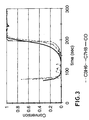
- the temperature of the inlet exhaust gas is ramped as shown in Figure 2.
- the reactor is held at that temperature for approximately 5 minutes, after which the exhaust gases are removed from the feed and the reactor is cooled down in a flow of dry air.
- the feed gas is switched back to argon and the experiment is repeated in a second run.
- Figures 3 and 4 show the light-off results over the two catalyst formulations in the second run.
- Figure 3 (Comparative Example 1), giving the results for the commercial catalyst, shows that the CO and hydrocarbons light off (a conversion figure of 0.5) as a group at approximately 190-200 seconds into the run.
- Figure 4 (Example 1), giving the results for the present catalyst under identical conditions, shows that it lights off almost instantly, converting all of the CO and nearly all of the hydrocarbon almost immediately after they have been introduced to the reactor. This illustrates that the present catalyst, when used with the present light-off strategy, produces remarkably fast light-off.
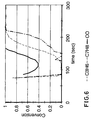
- Figures 5 and 6 show the results from two light-off tests over the present catalyst carried out in the manner described in Example 1 except as noted.
- Figure 5 (Example 2) shows the results of the first run using the catalyst fresh.
- Figure 6 (Comparative Example 2) shows the results of a third run, carried out immediately after the second run but after again cooling the catalyst in dry air. In this run, all reactor conditions were kept the same except that the CO feed level was set to 0.5% throughout the entire run.
- a comparison of Figures 5 and 4 shows the benefits of performing the runs over a catalyst which has been "pre-dried".
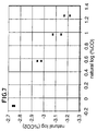
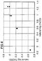
- Example 3 The effect of CO feed level on the rate of the CO oxidation reaction was examined under lean conditions (5% O 2 , 1-4% CO) for the comparative (Comparative Example 3) and present (Example 3) catalysts described in Example 1 and Comparative Example 1, though the catalysts were employed in powder form (not coated on a monolith).
- the results are summarised in the Table and in Figures 7 and 8.
- the comparative catalyst exhibits negative order CO kinetics for CO oxidation, meaning that increasing the amount of CO in the feed leads to a decreased rate of CO oxidation at feed levels of 1-4%.
- the present catalyst exhibits the reverse, positive order kinetics.
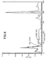
- Figure 9 shows feed gas (pre-catalyst) and tailpipe (post-catalyst) CO levels in terms of g/s.
- the CO light-off occurs at about 40 seconds into the test.
- Figure 10 shows the results for hydrocarbons, with the light-off again occurring at about 40 seconds into the test.
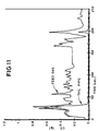
- Figures 11 and 12 show the same catalyst in a second test in which the amount of CO in the feed gas has been increased significantly (the O 2 level was also increased, in order to keep the same stoichiometry as in the test whose results are shown in Figures 9 and 10). In between test 1 and test 2, dry nitrogen was blown over the catalyst in order to "dry" the catalyst.
- Figures 11 and 12 there is virtually no advantage seen due to the higher inlet CO levels and the drying of the catalyst.
- the light-off times for each of these pollutants is almost unchanged.
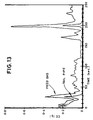
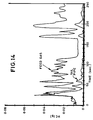
- Figures 13 and 14 show the lean light-off performance (Comparative Example 6) of the present catalyst using the normal engine start-up, except that an additional air source has been attached in order to ensure lean conditions over the catalyst at start-up.
- This experiment is the fourth in a series, so the catalyst has already undergone the "drying" treatment described above.
- Figures show an improvement in emissions compared to the results for the comparative catalyst shown in Figures 9-12, thus indicating the advantages of the present catalyst under these start-up conditions.
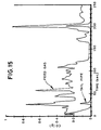
- Figures 15 and 16 show the performance (Example 4) of this catalyst in the FTP test where additional CO and O 2 have been injected over the catalyst as described above.
- a marked advantage in both CO and hydrocarbon light-off is observed as a result of the higher levels.
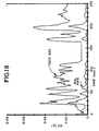
- Figures 19 and 20 show the results (Example 6) from test 2, in which the front underfloor position now contains a half-size brick coated with zeolite 5A (a desiccant material) followed by half-sized brick coated with ZSM5 ( a hydrocarbon trap). The rear underfloor position again contains the present catalyst. The excellent performance for CO oxidation is again shown in Figure 19.
- Figure 20 shows that the hydrocarbon trap effectively reduces the hydrocarbon emissions in the first 10-15 seconds of the experiment.
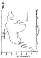
- the trace for the front underfloor position looks similar to the first 35 seconds of the comparative catalyst mid-bed temperature (before light-off occurs on the brick in Figure 21).
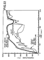
- the temperature of the rear underfloor brick increases very rapidly, reaching 200°C in the first 15 seconds of operation. It is important to note that this rapid catalyst heating occurs not due to the specific heat coming from the engine, but due to the heat of reaction from the CO, hydrogen and hydrocarbon combustion over the catalysts.
- the rapid temperature rise of the present catalyst shown in Figure 22 illustrates a further advantage of the present invention, in that a thermocouple placed within the catalyst may be simply used as a diagnostic means for catalyst performance.
- a catalyst has been prepared according to the following recipe: Tetraamine platinum hydrocarbonate (TPtHC) was dissolved in citric acid, and added to a Pd(NO 3 ) 2 solution. This solution was then mixed with a solid ceria-zirconia mixed oxide, which was 70% CeO 2 and 30% ZrO 2 by weight. This slurry was warmed gently to drive off the excess liquid, dried overnight, and then calcined at 500°C for 2 hours. The resulting catalyst was 4%Pd and 2%Pt by mass. This catalyst was then coated onto monolith substrates at a loading of 3g/in 3 (0.18g/cm 3 ), and loaded into the two underfloor positions of the Ford Contour.
- TPtHC Tetraamine platinum hydrocarbonate
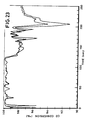
- Figures 23 and 24 show the conversion of CO and hydrocarbon as a function of time at start-up for two consecutive runs. It can be seen from Figure 23 that CO conversion is above 90% practically immediately, and remains high throughout the first 250 seconds of the test. Figure 24 shows that hydrocarbon conversion remains high throughout the crucial start-up phase of the test. Outstanding low temperature light-off behaviour has been achieved.
Landscapes
- Engineering & Computer Science (AREA)
- Chemical & Material Sciences (AREA)
- Combustion & Propulsion (AREA)
- Chemical Kinetics & Catalysis (AREA)
- General Engineering & Computer Science (AREA)
- Mechanical Engineering (AREA)
- Health & Medical Sciences (AREA)
- Oil, Petroleum & Natural Gas (AREA)
- General Chemical & Material Sciences (AREA)
- Analytical Chemistry (AREA)
- Environmental & Geological Engineering (AREA)
- Biomedical Technology (AREA)
- Materials Engineering (AREA)
- Toxicology (AREA)
- Exhaust Gas After Treatment (AREA)
- Exhaust Gas Treatment By Means Of Catalyst (AREA)
- Catalysts (AREA)
- Respiratory Apparatuses And Protective Means (AREA)
- Oxygen, Ozone, And Oxides In General (AREA)
- Filtering Of Dispersed Particles In Gases (AREA)
- Treating Waste Gases (AREA)
- Catching Or Destruction (AREA)
Applications Claiming Priority (5)
| Application Number | Priority Date | Filing Date | Title |
|---|---|---|---|
| GB9511421 | 1995-06-06 | ||
| GBGB9511421.1A GB9511421D0 (en) | 1995-06-06 | 1995-06-06 | Improvements in emissions control |
| GBGB9525413.2A GB9525413D0 (en) | 1995-12-13 | 1995-12-13 | Combatting air pollution |
| GB9525413 | 1995-12-13 | ||
| PCT/GB1996/001320 WO1996039576A1 (en) | 1995-06-06 | 1996-06-05 | Combatting air pollution |
Publications (2)
| Publication Number | Publication Date |
|---|---|
| EP0774054A1 EP0774054A1 (en) | 1997-05-21 |
| EP0774054B1 true EP0774054B1 (en) | 2002-02-20 |
Family
ID=26307167
Family Applications (1)
| Application Number | Title | Priority Date | Filing Date |
|---|---|---|---|
| EP96919964A Expired - Lifetime EP0774054B1 (en) | 1995-06-06 | 1996-06-05 | Combatting air pollution |
Country Status (9)
| Country | Link |
|---|---|
| US (1) | US5939028A (enExample) |
| EP (1) | EP0774054B1 (enExample) |
| JP (1) | JP3952314B2 (enExample) |
| AT (1) | ATE213522T1 (enExample) |
| AU (1) | AU705112B2 (enExample) |
| BR (1) | BR9606433A (enExample) |
| CA (1) | CA2196904A1 (enExample) |
| DE (1) | DE69619342T2 (enExample) |
| WO (1) | WO1996039576A1 (enExample) |
Families Citing this family (28)
| Publication number | Priority date | Publication date | Assignee | Title |
|---|---|---|---|---|
| US6793899B2 (en) * | 1998-10-29 | 2004-09-21 | Massachusetts Institute Of Technology | Plasmatron-catalyst system |
| GB9718059D0 (en) | 1997-08-28 | 1997-10-29 | Johnson Matthey Plc | Improvements relating to catalysts |
| US6074973A (en) * | 1998-03-20 | 2000-06-13 | Engelhard Corporation | Catalyzed hydrocarbon trap material and method of making the same |
| JP3518338B2 (ja) * | 1998-05-29 | 2004-04-12 | 日産自動車株式会社 | 内燃機関の排気浄化装置 |
| GB2340054B (en) * | 1998-07-24 | 2001-11-07 | Johnson Matthey Plc | Combatting air pollution |
| GB9905550D0 (en) | 1999-03-11 | 1999-05-05 | Johnson Matthey Plc | Improvements in catalyst systems |
| EP1186764A3 (en) * | 2000-09-07 | 2003-11-12 | Nissan Motor Co., Ltd. | Engine exhaust gas purification device |
| JP3716738B2 (ja) * | 2000-11-06 | 2005-11-16 | 日産自動車株式会社 | 内燃機関の排気浄化装置 |
| JP3636116B2 (ja) * | 2001-03-21 | 2005-04-06 | 日産自動車株式会社 | 内燃機関の排気浄化装置 |
| DE10205968A1 (de) | 2002-02-14 | 2003-08-21 | Bosch Gmbh Robert | Diagnose eines Wasser-Adsorbers im Abgas eines Verbrennungsmotors |
| WO2003093734A1 (en) | 2002-04-29 | 2003-11-13 | Acron International Technology Limited | Air cleaner filter system capable of nano-confined catalytic oxidation |
| JP2004092535A (ja) * | 2002-08-30 | 2004-03-25 | Mitsubishi Motors Corp | 排ガス浄化装置 |
| JP2005538300A (ja) | 2002-09-13 | 2005-12-15 | ジョンソン、マッセイ、パブリック、リミテッド、カンパニー | 圧縮着火機関およびそのための排気機構 |
| US20040094035A1 (en) * | 2002-11-20 | 2004-05-20 | Ford Global Technologies, Inc. | Method and apparatus to improve catalyzed hydrocarbon trap efficiency |
| DE10357887A1 (de) * | 2003-11-14 | 2005-06-16 | Volkswagen Ag | Brennkraftmaschine mit einer Abgasreinigungsvorrichtung und Verfahren zum Betrieb einer Brennkraftmaschine |
| CN100448786C (zh) * | 2004-08-31 | 2009-01-07 | 罗瑞真 | 一种流体净化方法及其装置 |
| US8115373B2 (en) | 2005-07-06 | 2012-02-14 | Rochester Institute Of Technology | Self-regenerating particulate trap systems for emissions and methods thereof |
| EP1970118A1 (en) | 2007-03-14 | 2008-09-17 | Ford Global Technologies, LLC | Oxidation catalyst, method of making such catalyst and IC engine using such catalyst |
| WO2009110373A1 (ja) * | 2008-03-03 | 2009-09-11 | トヨタ自動車株式会社 | 内燃機関の排気浄化装置 |
| GB201003784D0 (en) | 2010-03-08 | 2010-04-21 | Johnson Matthey Plc | Improvement in control OPF emissions |
| JP4998579B2 (ja) | 2010-04-01 | 2012-08-15 | トヨタ自動車株式会社 | 排気浄化触媒 |
| EP2374536A1 (en) | 2010-04-08 | 2011-10-12 | Ford Global Technologies, LLC | Palladium-containing oxidation catalyst on ternary Al-Ti-Zr-oxide |
| JP6191380B2 (ja) * | 2013-10-17 | 2017-09-06 | いすゞ自動車株式会社 | 内燃機関の排気ガス浄化システム及び内燃機関の排気ガス浄化方法 |
| GB201322842D0 (en) * | 2013-12-23 | 2014-02-12 | Johnson Matthey Plc | Exhaust system for a compression ingition engine comprising a water absorbent material |
| CN107810058B (zh) | 2015-06-29 | 2022-01-25 | 康宁股份有限公司 | 减少排放物的多孔陶瓷体 |
| DE102020216153B3 (de) * | 2020-12-17 | 2022-02-03 | Vitesco Technologies GmbH | Verfahren zur Reinigung eines Speicherkatalysators und Vorrichtung hierzu |
| US11648329B1 (en) | 2021-11-24 | 2023-05-16 | Rht Limited | Air purifiers |
| CN119857363A (zh) * | 2023-10-20 | 2025-04-22 | 中国石油化工股份有限公司 | 一种催化氧化脱除co的方法及其应用 |
Family Cites Families (14)
| Publication number | Priority date | Publication date | Assignee | Title |
|---|---|---|---|---|
| JPS5389482A (en) * | 1977-01-17 | 1978-08-07 | Mitsubishi Electric Corp | Temperature display device of exhaust gas purifier |
| JPS5471225A (en) * | 1977-11-17 | 1979-06-07 | Nissan Motor Co Ltd | Catalyzer converter for automobile |
| JPS6093110A (ja) * | 1983-10-26 | 1985-05-24 | Matsushita Electric Ind Co Ltd | エンジン排熱回収装置 |
| US5296198A (en) * | 1990-11-09 | 1994-03-22 | Ngk Insulators, Ltd. | Heater and catalytic converter |
| DE4117364A1 (de) * | 1991-05-28 | 1992-12-03 | Duerrwaechter E Dr Doduco | Verfahren zum verkuerzen der anspringverzoegerung eines katalysators und vorrichtung zur durchfuehrung des verfahrens |
| JP2946064B2 (ja) * | 1991-08-29 | 1999-09-06 | 株式会社日立製作所 | エンジン排気浄化装置 |
| JPH05285387A (ja) * | 1992-04-13 | 1993-11-02 | Hitachi Ltd | 排ガス浄化触媒及び方法 |
| CA2094763A1 (en) * | 1992-08-05 | 1994-02-06 | William Hertl | System and method for removing hydrocarbons from gaseous mixtures |
| DE69307822T2 (de) * | 1992-10-20 | 1997-08-21 | Corning Inc | Verfahren zur Konvertierung von Abgasen und Vorrichtung mit thermisch stabilen Zeolithen |
| JP3311051B2 (ja) * | 1992-12-16 | 2002-08-05 | 日本碍子株式会社 | 排気ガス浄化方法及び装置 |
| GB9226434D0 (en) * | 1992-12-18 | 1993-02-10 | Johnson Matthey Plc | Catalyst |
| JPH06319948A (ja) * | 1993-05-07 | 1994-11-22 | Toray Ind Inc | 排気ガス処理装置 |
| US5397550A (en) * | 1994-02-14 | 1995-03-14 | Marino, Jr.; Robert R. | Catalytic converter and cleaning system |
| GB9511421D0 (en) * | 1995-06-06 | 1995-08-02 | Johnson Matthey Plc | Improvements in emissions control |
-
1996
- 1996-06-05 AT AT96919964T patent/ATE213522T1/de not_active IP Right Cessation
- 1996-06-05 CA CA002196904A patent/CA2196904A1/en not_active Abandoned
- 1996-06-05 BR BR9606433A patent/BR9606433A/pt not_active Application Discontinuation
- 1996-06-05 DE DE69619342T patent/DE69619342T2/de not_active Expired - Fee Related
- 1996-06-05 WO PCT/GB1996/001320 patent/WO1996039576A1/en not_active Ceased
- 1996-06-05 AU AU58424/96A patent/AU705112B2/en not_active Ceased
- 1996-06-05 EP EP96919964A patent/EP0774054B1/en not_active Expired - Lifetime
- 1996-06-05 JP JP50021797A patent/JP3952314B2/ja not_active Expired - Fee Related
-
1997
- 1997-02-04 US US08/795,388 patent/US5939028A/en not_active Expired - Lifetime
Also Published As
| Publication number | Publication date |
|---|---|
| EP0774054A1 (en) | 1997-05-21 |
| AU5842496A (en) | 1996-12-24 |
| DE69619342T2 (de) | 2002-10-02 |
| CA2196904A1 (en) | 1996-12-12 |
| DE69619342D1 (de) | 2002-03-28 |
| US5939028A (en) | 1999-08-17 |
| JPH10504370A (ja) | 1998-04-28 |
| MX9700913A (es) | 1998-03-31 |
| WO1996039576A1 (en) | 1996-12-12 |
| BR9606433A (pt) | 1997-09-30 |
| AU705112B2 (en) | 1999-05-13 |
| JP3952314B2 (ja) | 2007-08-01 |
| ATE213522T1 (de) | 2002-03-15 |
Similar Documents
| Publication | Publication Date | Title |
|---|---|---|
| EP0774054B1 (en) | Combatting air pollution | |
| US9810120B2 (en) | Exhaust gas purifying system | |
| US8105559B2 (en) | Thermally regenerable nitric oxide adsorbent | |
| US5727385A (en) | Lean-burn nox catalyst/nox trap system | |
| US6477831B1 (en) | Combatting air pollution | |
| EP1313934B1 (en) | Exhaust system for lean-burn engines | |
| MX2007006113A (es) | Sistema de escape que comprende catalizador generador de exotermia. | |
| US9446395B2 (en) | Low temperature catalyst/hydrocarbon trap | |
| US8448421B2 (en) | HC adsorber with OBD capability | |
| JP2003536011A (ja) | NOxトラップを包含するディーゼル排気機構 | |
| US5950421A (en) | Tungsten-modified platinum NOx traps for automotive emission reduction | |
| JPH0559937A (ja) | エンジン排気浄化装置 | |
| MXPA97000913A (en) | Fighter of the contamination of the | |
| JPH11285624A (ja) | 自動車の排出物削減のための白金/アルミナ・窒素酸化物ト ラップの使用 |
Legal Events
| Date | Code | Title | Description |
|---|---|---|---|
| PUAI | Public reference made under article 153(3) epc to a published international application that has entered the european phase |
Free format text: ORIGINAL CODE: 0009012 |
|
| AK | Designated contracting states |
Kind code of ref document: A1 Designated state(s): AT BE DE DK FR GB IT NL SE |
|
| 17P | Request for examination filed |
Effective date: 19970519 |
|
| 17Q | First examination report despatched |
Effective date: 19991201 |
|
| GRAG | Despatch of communication of intention to grant |
Free format text: ORIGINAL CODE: EPIDOS AGRA |
|
| GRAG | Despatch of communication of intention to grant |
Free format text: ORIGINAL CODE: EPIDOS AGRA |
|
| GRAH | Despatch of communication of intention to grant a patent |
Free format text: ORIGINAL CODE: EPIDOS IGRA |
|
| RAP1 | Party data changed (applicant data changed or rights of an application transferred) |
Owner name: JOHNSON MATTHEY PUBLIC LIMITED COMPANY |
|
| GRAH | Despatch of communication of intention to grant a patent |
Free format text: ORIGINAL CODE: EPIDOS IGRA |
|
| REG | Reference to a national code |
Ref country code: GB Ref legal event code: IF02 |
|
| GRAA | (expected) grant |
Free format text: ORIGINAL CODE: 0009210 |
|
| AK | Designated contracting states |
Kind code of ref document: B1 Designated state(s): AT BE DE DK FR GB IT NL SE |
|
| PG25 | Lapsed in a contracting state [announced via postgrant information from national office to epo] |
Ref country code: NL Free format text: LAPSE BECAUSE OF FAILURE TO SUBMIT A TRANSLATION OF THE DESCRIPTION OR TO PAY THE FEE WITHIN THE PRESCRIBED TIME-LIMIT Effective date: 20020220 Ref country code: IT Free format text: LAPSE BECAUSE OF FAILURE TO SUBMIT A TRANSLATION OF THE DESCRIPTION OR TO PAY THE FEE WITHIN THE PRESCRIBED TIME-LIMIT;WARNING: LAPSES OF ITALIAN PATENTS WITH EFFECTIVE DATE BEFORE 2007 MAY HAVE OCCURRED AT ANY TIME BEFORE 2007. THE CORRECT EFFECTIVE DATE MAY BE DIFFERENT FROM THE ONE RECORDED. Effective date: 20020220 Ref country code: BE Free format text: LAPSE BECAUSE OF FAILURE TO SUBMIT A TRANSLATION OF THE DESCRIPTION OR TO PAY THE FEE WITHIN THE PRESCRIBED TIME-LIMIT Effective date: 20020220 Ref country code: AT Free format text: LAPSE BECAUSE OF FAILURE TO SUBMIT A TRANSLATION OF THE DESCRIPTION OR TO PAY THE FEE WITHIN THE PRESCRIBED TIME-LIMIT Effective date: 20020220 |
|
| REF | Corresponds to: |
Ref document number: 213522 Country of ref document: AT Date of ref document: 20020315 Kind code of ref document: T |
|
| REF | Corresponds to: |
Ref document number: 69619342 Country of ref document: DE Date of ref document: 20020328 |
|
| PG25 | Lapsed in a contracting state [announced via postgrant information from national office to epo] |
Ref country code: SE Free format text: LAPSE BECAUSE OF FAILURE TO SUBMIT A TRANSLATION OF THE DESCRIPTION OR TO PAY THE FEE WITHIN THE PRESCRIBED TIME-LIMIT Effective date: 20020520 Ref country code: DK Free format text: LAPSE BECAUSE OF FAILURE TO SUBMIT A TRANSLATION OF THE DESCRIPTION OR TO PAY THE FEE WITHIN THE PRESCRIBED TIME-LIMIT Effective date: 20020520 |
|
| ET | Fr: translation filed | ||
| NLV1 | Nl: lapsed or annulled due to failure to fulfill the requirements of art. 29p and 29m of the patents act | ||
| PLBE | No opposition filed within time limit |
Free format text: ORIGINAL CODE: 0009261 |
|
| STAA | Information on the status of an ep patent application or granted ep patent |
Free format text: STATUS: NO OPPOSITION FILED WITHIN TIME LIMIT |
|
| 26N | No opposition filed |
Effective date: 20021121 |
|
| PGFP | Annual fee paid to national office [announced via postgrant information from national office to epo] |
Ref country code: DE Payment date: 20080523 Year of fee payment: 13 |
|
| PGFP | Annual fee paid to national office [announced via postgrant information from national office to epo] |
Ref country code: GB Payment date: 20080521 Year of fee payment: 13 |
|
| GBPC | Gb: european patent ceased through non-payment of renewal fee |
Effective date: 20090605 |
|
| REG | Reference to a national code |
Ref country code: FR Ref legal event code: ST Effective date: 20100226 |
|
| PG25 | Lapsed in a contracting state [announced via postgrant information from national office to epo] |
Ref country code: FR Free format text: LAPSE BECAUSE OF NON-PAYMENT OF DUE FEES Effective date: 20090630 |
|
| PGFP | Annual fee paid to national office [announced via postgrant information from national office to epo] |
Ref country code: FR Payment date: 20080513 Year of fee payment: 13 |
|
| PG25 | Lapsed in a contracting state [announced via postgrant information from national office to epo] |
Ref country code: GB Free format text: LAPSE BECAUSE OF NON-PAYMENT OF DUE FEES Effective date: 20090605 |
|
| PG25 | Lapsed in a contracting state [announced via postgrant information from national office to epo] |
Ref country code: DE Free format text: LAPSE BECAUSE OF NON-PAYMENT OF DUE FEES Effective date: 20100101 |