EP0773711A2 - Halterkörper für Bauteil - Google Patents
Halterkörper für Bauteil Download PDFInfo
- Publication number
- EP0773711A2 EP0773711A2 EP96117802A EP96117802A EP0773711A2 EP 0773711 A2 EP0773711 A2 EP 0773711A2 EP 96117802 A EP96117802 A EP 96117802A EP 96117802 A EP96117802 A EP 96117802A EP 0773711 A2 EP0773711 A2 EP 0773711A2
- Authority
- EP
- European Patent Office
- Prior art keywords
- component
- holding
- arrangement section
- projecting
- holder body
- Prior art date
- Legal status (The legal status is an assumption and is not a legal conclusion. Google has not performed a legal analysis and makes no representation as to the accuracy of the status listed.)
- Ceased
Links
- 238000009434 installation Methods 0.000 claims abstract description 13
- 230000008878 coupling Effects 0.000 claims description 54
- 238000010168 coupling process Methods 0.000 claims description 54
- 238000005859 coupling reaction Methods 0.000 claims description 54
- 230000002093 peripheral effect Effects 0.000 claims description 44
- 230000000694 effects Effects 0.000 description 4
- 238000001746 injection moulding Methods 0.000 description 4
- 238000012986 modification Methods 0.000 description 2
- 230000004048 modification Effects 0.000 description 2
- -1 polypropylene Polymers 0.000 description 2
- 239000004698 Polyethylene Substances 0.000 description 1
- 239000004743 Polypropylene Substances 0.000 description 1
- 230000003247 decreasing effect Effects 0.000 description 1
- 238000004049 embossing Methods 0.000 description 1
- 238000000465 moulding Methods 0.000 description 1
- 229920000573 polyethylene Polymers 0.000 description 1
- 229920001155 polypropylene Polymers 0.000 description 1
- 230000035939 shock Effects 0.000 description 1
Images


Classifications
-
- H—ELECTRICITY
- H05—ELECTRIC TECHNIQUES NOT OTHERWISE PROVIDED FOR
- H05K—PRINTED CIRCUITS; CASINGS OR CONSTRUCTIONAL DETAILS OF ELECTRIC APPARATUS; MANUFACTURE OF ASSEMBLAGES OF ELECTRICAL COMPONENTS
- H05K13/00—Apparatus or processes specially adapted for manufacturing or adjusting assemblages of electric components
- H05K13/003—Placing of components on belts holding the terminals
-
- B—PERFORMING OPERATIONS; TRANSPORTING
- B65—CONVEYING; PACKING; STORING; HANDLING THIN OR FILAMENTARY MATERIAL
- B65D—CONTAINERS FOR STORAGE OR TRANSPORT OF ARTICLES OR MATERIALS, e.g. BAGS, BARRELS, BOTTLES, BOXES, CANS, CARTONS, CRATES, DRUMS, JARS, TANKS, HOPPERS, FORWARDING CONTAINERS; ACCESSORIES, CLOSURES, OR FITTINGS THEREFOR; PACKAGING ELEMENTS; PACKAGES
- B65D73/00—Packages comprising articles attached to cards, sheets or webs
- B65D73/02—Articles, e.g. small electrical components, attached to webs
-
- Y—GENERAL TAGGING OF NEW TECHNOLOGICAL DEVELOPMENTS; GENERAL TAGGING OF CROSS-SECTIONAL TECHNOLOGIES SPANNING OVER SEVERAL SECTIONS OF THE IPC; TECHNICAL SUBJECTS COVERED BY FORMER USPC CROSS-REFERENCE ART COLLECTIONS [XRACs] AND DIGESTS
- Y10—TECHNICAL SUBJECTS COVERED BY FORMER USPC
- Y10S—TECHNICAL SUBJECTS COVERED BY FORMER USPC CROSS-REFERENCE ART COLLECTIONS [XRACs] AND DIGESTS
- Y10S206/00—Special receptacle or package
- Y10S206/82—Separable, striplike plural articles
Definitions
- the present invention relates to a component holder body for storing/holding various kinds of components, e.g., mechanical components, electronic components, etc.
- a component holder body 31 As shown in Fig. 15 has been used.
- the holder body 31 utilizes a holding tape 32 with many storing recesses embossed every predetermined distance therein.
- An upper surface of the holding tape 32 after components are accommodated in the recesses 33 is covered with a cover tape 34 to prevent the components from popping out.
- the component holder body 31 since the size accuracy of the recesses 33 formed by embossing cannot be high, it is impossible to surely hold the components in the recesses 33 not to move. If the components have soft or weak projections, the components may be possibly given a shock and damaged during the transfer or supply. Moreover, since it is necessary to cover the components with the cover tape 34 when the components are stored and to strip off and rewind the cover tape 34 when the components are supplied, the component feed device becomes complicated in structure. The stripped cover tape 34 is dumped, not recycled, thus inviting an increase of costs.
- an object of the present invention is to provide a component holder body which can surely hold components and is reusable wholly.
- a component holder body comprising:
- the component when the arrangement section is shifted to the projecting position thereby to retreat the holding parts, the component is disposed in the arrangement section from above. Thereafter, the arrangement section is shifted to the holding position, whereby the component is securely held by the holding parts.
- the component holder body as defined in the first aspect, wherein the holder body is constituted of a plurality of holder units coupled one another, each of the holder units comprising the component arrangement section and the holding parts and further comprising coupling parts at both side edges thereof, wherein the component arrangement section is disposed inside a peripheral frame of the holder unit, and at least one of a pair of confronting side edges of the component arrangement section is coupled with an inner edge of the peripheral frame facing the side edge by means of self hinges via a link, with the holding part being integrally extended from the link.
- the component holder body as defined in the first aspect, wherein the holder body is constituted of a plurality of holder units coupled one another, each of the holder units comprising the component arrangement section and the holding parts and further comprising coupling parts at both side edges thereof, wherein both ends of a pair of links coupled via a first self hinge are coupled via second self hinges with inner edges of a peripheral frame facing each other, and the component arrangement section is provided at a central part including a coupled portion of the pair of the links, with the holding parts being integrally extended from the pair of the links.
- the holder unit when the holder unit is formed by injection molding, the holder unit can be molded accurately, thereby holding the component more surely. Since the arrangement section is coupled to the peripheral frame by the links and self hinges, this smoothly and stably shifts the arrangement section between two positions and ensures long-time use.
- the component holder body as defined in the second or third aspect, wherein the coupling part is constituted of a coupling hole formed at one side edge of the peripheral frame, an engaging projection projecting at the other side edge of the peripheral frame to be fitted in the coupling hole, and an engaging hook projecting at a side face of the engaging projection to be engaged with a peripheral edge portion of the coupling hole in a state while the engaging projection is inserted into the coupling hole.
- the coupling part is constituted of a coupling hole formed at one side edge of the peripheral frame, an engaging projection projecting at the other side edge of the peripheral frame to be fitted in the coupling hole, and an engaging hook projecting at a side face of the engaging projection to be engaged with a peripheral edge portion of the coupling hole in a state while the engaging projection is inserted into the coupling hole.
- the holder units can be coupled easily and not separated unexpectedly. Accordingly, the holder unit can be used with high reliability.
- the component holder body as defined in the first aspect, wherein the component arrangement section is constituted of a recessed portion formed in an elastically deformable tape body, the tape body being elastically shiftable between a sinking state from one face of the tape body and a projecting state, and each of the holding parts is constituted of a part of an outer peripheral portion of a wall forming the recessed portion which is turned up therefrom.
- the holder unit can surely hold and repeatedly store/take out the component similar to the above in a simple manipulation. Moreover, the holder unit can be reused as it is.
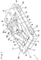
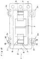
- a component holder body in one embodiment of the present invention will be described with reference to Figs. 1-3.
- Reference numeral 2 is a holder unit. Many holder units 2 are coupled at coupling parts 2a at both sides thereof, thereby constituting a component holder body 1. Each holder unit 2 stores/holds a component thereinside. A tape-like collective body of components is thus formed.
- the holder unit 2 is formed of polypropylene or polyethylene by injection molding into a nearly rectangular shape in a plan view, specifically, longer in a direction orthogonal to a coupling direction thereof.
- the holder unit 2 has a peripheral frame 3 of an inverted L in a cross section, and feed holes 4 via a predetermined pitch at one side portion in parallel to the coupling direction.
- a component arrangement section 5 is provided inside the peripheral frame 3, which forms an installation space 5a for a component.
- Self hinges 7 couple each of a pair of confronting side edges of the component arrangement section 5 confronting in the direction orthogonal to the coupling direction at an intermediate position in a vertical direction of the section, with an upper end of an inner edge of the peripheral frame 3 facing the side edge, via a pair of parallel links 6.
- the length of the link 6 is set to be slightly larger than half a distance obtained by subtracting the distance of the pairing side edges of the arrangement section 5 from the distance of inner edges of the peripheral frame 3.
- the component arrangement section 5 is consequently rendered shiftable between a holding position located lower than an upper surface of the peripheral frame 3 as shown in Fig.
- the component arrangement section 5 is shaped into a bottomed, schematically cylindrical form, with having a supporting step portion 5b at a middle position in a heightwise direction, a large-diameter cylindrical portion 5c over the supporting step portion 5b to be outfitted in the outer periphery of the component, and notched portions 5d at both sides of the cylindrical portion 5c to which holding parts 9 to be described in the following are inserted.
- the pair of links 6, 6 arranged in parallel are coupled at a coupling part 6a into one body.
- the holding part 9 referred to hereinabove is integrally extended slightly slantwise upward to the pair of links 6 from the coupling part 6a to hold the component 8 set in the arrangement section 5.
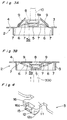
- the holding parts 9 Interlocking with the shift of the arrangement section 5 between the projecting position and holding position as shown in Figs. 3A and 3B while the links 6 oscillate up and down, the holding parts 9 shift between a retreat posture where the holding parts 9 are opened up and a holding posture for holding the component 8.
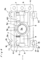
- An engaging projection 12 projects upward at a front end part of the coupling element 11.
- a pair of projecting portions 13 are formed at positions corresponding to the coupling elements 11.
- a coupling hole 14 is formed in the projecting portion 13 into which the engaging projection 12 is fitted.
- a coupling part 2a is constituted of the engaging projection 12 and the coupling hole 14.
- the engaging projection 12 has a sharp projecting portion 12a at the lower end thereof and an engaging hook 15 projecting at an outer face thereof.
- a cave portion 16 of a larger width than that of the engaging hook 15 is formed inside the engaging hook 15 and both the ends of the engaging hook 15 and the side end walls of the cave portion 16 are connected to each other via thin connection walls 16a, so that the engaging hook 15 is let to sink into the cave portion 16 by the application of a suitable external force or is surely restored.
- a face 17 at a peripheral side face of the coupling hole 14 corresponding to the engaging hook 15 is engaged with the engaging hook 15 when the engaging projection 12 is completely fitted into the coupling hole 14.
- the coupling hole 14 of one holder unit 2 is positioned below the engaging projection 12 of the other holder unit 2, then the other holder unit 2 is descended thereby to insert the engaging projection 12 of the other holder unit 12 into the coupling hole 14 of the one holder unit 2.
- the engaging hook 15 is returned after retreated into the cave portion 16, and engaged with the face 17 formed at one side face of the coupling hole 14 of the one holder unit 2. Accordingly, the engaging projection 12 is prevented from slipping out of the coupling hole 14 and the holder units 2 are surely coupled with each other. Owing to the engaging hook 15 provided at the engaging projection 12, the holder units 2 can be easily coupled not to be separated unexpectedly from each other simply by inserting the engaging projection 12 into the coupling hole 14.
- the component arrangement section 5 is pressed from below by an appropriate push means such as a bar 300 in Fig. 3B to the projecting position, as indicated in Fig. 3A.
- the holding parts 9 are brought into the retreat posture thereby to open the installation space 5a.
- the component 8 held by a suction nozzle 10 or the like is inserted from above into the component arrangement section 5 which in turn is pressed down directly.
- the component arrangement section 5 is positioned at the holding position, as shown in Fig. 3B.
- the holding parts 9 enter the notched portions 5d thereby to hold the component 8 from above, so that the component 8 is tightly held not to move in this manner.
- the component arrangement section 5 is pushed from below by the suitable push means 300 from the state of Fig. 3B up to the projecting position shown in Fig. 3A. Then, the component 8 is caught and taken out by the suction nozzle 10 or the like. At this time, in a case where it seems that there is a danger that the component 8 held in the component arrangement section 5 might pop up therefrom because the component 8 is moved from the holding position to the projecting position to some great extent, it is better that the suction nozzle 10 is waited at the position shown by the dotted lines in Fig. 3A so as to receive the component 8 moved from the holding position to the projecting position by the lower end of the suction nozzle 10.
- the holding parts 9 are brought into the retreat posture by shifting the component arrangement section 5 to the projecting position, and the component 8 is arranged at the arrangement section 5 from above. Subsequently, the component arrangement section 5 is shifted to the holding position, whereby the component 8 is surely held by the holding parts 9. Since the holder unit 2 is formed by injection molding, that is, can be molded with good accuracy, the component 8 can be held furthermore surely. Moreover, since the arrangement section 5 is coupled to the peripheral frame 3 by the links 6 and self hinges 7, the arrangement section 5 is allowed to shift between the two positions smoothly and stably and endures long-time use.
- the holder unit 2 is molded while the component arrangement section 5 is positioned at the projecting position as in Figs. 1-3A not to overlap with the holding parts 9 in a plan view and not to interfere with each other.
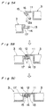
- each of the holding portions 9 has a flat plate in the first embodiment in Figs. 1-3B
- each of holding portions 90 can have a bent portion 90a at the front end of the main body 90 as shown in Figs. 6 and 7 so that a flatter component 8 is pressed by the bent portions 90a of the holding portions 90 in the component arrangement section 5 at the holding position. That is, the configuration of the holding portion can be formed in accordance with the configuration of a component to be held in the component arrangement section 5.
- a pair of links 6 is arranged at each side of the component arrangement section 5. It is needless to say, however, that as a third embodiment of the present invention, a wide single link 60 will do if the link 30 is disposed at each side of the arrangement section 5 in a manner not to incline the arrangement section 5 in a widthwise direction of the link 60. Still, a pair of links 6 is more preferable so that the link 6 does not overlap with the holding part 9 in a plan view at the molding occasion.
- the component arrangement section 5 may be coupled only at one side (right side in Figs. 9A and 9B) thereof with the confronting inner edge of the peripheral frame 3 by the self hinges 7 via the links 6, while the component arrangement section 5 is directly coupled at the other side (left side in Figs. 9A and 9B) thereof with the inner edge of the peripheral frame 3 by the self hinge 7. This achieves the same effect.
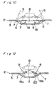
- a fifth embodiment of the component holder body of the present invention will be described with reference to Figs. 10 and 11.
- the fifth embodiment is basically equal to the first embodiment and simply the shape of the component arrangement section 5, etc. is different. More specifically, the component arrangement section 5 is obtained by projecting L-shaped frames 18 for positioning a rectangular component 8 at a central portion of a flat bottom plate.
- the link 6 is an inverted L in a cross section, from a corner of which the holding part 9 is extended.
- the component holder body of the fifth embodiment works the same operation as the above first embodiment.
- a component holder body according to a sixth embodiment of the present invention will be depicted with reference to Figs. 12 and 13. Both ends of a pair of links 19a, 19b coupled via the self hinge 7 are coupled via self hinges 7 to the inner edges of the peripheral frame 3 confronting each other.
- a component arrangement section 20 is defined at a central part including the coupled portion of the pair of links 19a, 19b, and the holding part 9 is integrally extended from each link 19a, 19b.
- the component arrangement section 20 can shift between the holding position indicated by solid lines and the projecting position indicated by virtual lines when the pair of links 19a, 19b oscillate up and down.
- the holding parts 9 shift between the holding posture and retreat posture, with nearly the same effect attained as in the above embodiments.
- a component holder body according to a seventh embodiment of the present invention will be depicted with reference to Figs. 14A and 14B. Many injection-molded holder units 2 are coupled thereby to constitute the component holder body 1 in any of the foregoing embodiments.
- an elastic deformable tape body 21 is used, and a recessed portion 22 is formed in the tape body 21.
- the recessed portion 22 is elastically shiftable between a state sinking from one face of the tape body 21 and a state projecting from the face.
- This recessed portion 22 serves as the component arrangement section 5.
- cut and turned-up elements 23 are formed at a plurality of points (three points in the illustrated example) of an outer peripheral portion of a wall forming the recessed portion 22, which constitute the holding part 9.
- the component 8 when the recessed portion 22 is in the sinking state shown by solid lines, the component 8 is set at the component arrangement section 5 constituted of the recessed portion 22 and held by the holding part 9 consisting of the turned-up elements 23.
- the holding parts 9 cut and turned up from the wall are brought into the retreat posture to open an upper part of the component arrangement section 20. Substantially the same effect as in the foregoing embodiments is accordingly achieved.
- the component arrangement section constituting the installation space for a component is adapted to shift between the holding position and the projecting position projecting up from the holding position.
- the holding parts are designed to shift between the holding posture for holding the component and the retreat posture for opening the installation space, in association with the shift of the component arrangement section between the holding and projecting positions. Accordingly, the component can be set or taken out from above to the component arrangement section at the projecting position, and moreover surely held by the holding parts by shifting the component arrangement section to the holding position. Since the total holder body is reusable, costs for feeding of components can be decreased.
- the component holder body is formed by coupling a plurality of holder units which have coupling parts at both side edges thereof.
- the holder unit has the component arrangement section inside the peripheral frame thereof.
- the component arrangement section is coupled with the inner edges of the peripheral frame by the self hinges via the links.
- the holding parts are integrally extended from the links.
- the holder unit can be formed with good accuracy by injection molding, thereby more surely holding the component. Since the component arrangement section is coupled with the peripheral frame by the links and self hinges, the component arrangement section can shift smoothly between the two positions and can be used stably for a long time.
- the coupling part is constituted of the coupling hole at one side edge of the peripheral frame, the engaging projection at the other side edge of the peripheral frame to be fitted in the coupling hole and, the engaging hook projecting at the side face of the engaging projection to be engageable with the peripheral edge portion of the coupling hole when the engaging projection is inserted into the coupling hole, the holder units can be coupled easily with each other and not separated unexpectedly. Highly reliable use is ensured.
- the component holder body can surely hold and repeatedly accommodate/take out the component similar to the above in a simple manipulation and moreover can be reused directly as it is.
Landscapes
- Engineering & Computer Science (AREA)
- Manufacturing & Machinery (AREA)
- Microelectronics & Electronic Packaging (AREA)
- Mechanical Engineering (AREA)
- Packaging Frangible Articles (AREA)
- Clamps And Clips (AREA)
- Packages (AREA)
- Supports For Pipes And Cables (AREA)
- Chain Conveyers (AREA)
Applications Claiming Priority (2)
| Application Number | Priority Date | Filing Date | Title |
|---|---|---|---|
| JP7292554A JPH09133121A (ja) | 1995-11-10 | 1995-11-10 | 部品保持体 |
| JP292554/95 | 1995-11-10 |
Publications (2)
| Publication Number | Publication Date |
|---|---|
| EP0773711A2 true EP0773711A2 (de) | 1997-05-14 |
| EP0773711A3 EP0773711A3 (de) | 1999-03-03 |
Family
ID=17783275
Family Applications (1)
| Application Number | Title | Priority Date | Filing Date |
|---|---|---|---|
| EP96117802A Ceased EP0773711A3 (de) | 1995-11-10 | 1996-11-07 | Halterkörper für Bauteil |
Country Status (7)
| Country | Link |
|---|---|
| US (1) | US5727688A (de) |
| EP (1) | EP0773711A3 (de) |
| JP (1) | JPH09133121A (de) |
| KR (1) | KR100250236B1 (de) |
| CN (1) | CN1048791C (de) |
| SG (1) | SG43440A1 (de) |
| TW (1) | TW381151B (de) |
Cited By (1)
| Publication number | Priority date | Publication date | Assignee | Title |
|---|---|---|---|---|
| DE102008042195A1 (de) | 2007-12-20 | 2009-06-25 | Patek Philippe Sa | Transportvorrichtung für Werkstücke |
Families Citing this family (13)
| Publication number | Priority date | Publication date | Assignee | Title |
|---|---|---|---|---|
| CN1099828C (zh) | 1995-09-22 | 2003-01-22 | 松下电器产业株式会社 | 零件夹持器 |
| US6404181B1 (en) * | 1996-10-17 | 2002-06-11 | Matsushita Electric Industrial Co., Ltd. | Parts container, method of inspecting parts using same, and apparatus therefor |
| EP0950620B1 (de) * | 1996-11-18 | 2003-02-26 | Matsushita Electric Industrial Co., Ltd. | BAUTEILBEHäLTER |
| US5908114A (en) * | 1997-09-09 | 1999-06-01 | Gelpak, Llc | Tape carrier for electronic and electrical parts |
| USD422209S (en) * | 1998-12-30 | 2000-04-04 | Sony Corporation | Case for component |
| US6215669B1 (en) * | 1999-02-10 | 2001-04-10 | Methode Electronics, Inc. | Discrete component in-mold mounting |
| US6047832A (en) * | 1999-08-13 | 2000-04-11 | Advantek, Inc. | Component carrier tape |
| KR100486412B1 (ko) * | 2000-10-18 | 2005-05-03 | (주)테크윙 | 테스트 핸들러의 테스트 트레이 인서트 |
| DE102008044368B3 (de) * | 2008-12-05 | 2009-11-12 | Hilti Aktiengesellschaft | Befestigungselemente-Magazinstreifen |
| CN107223185B (zh) * | 2015-05-20 | 2020-03-10 | 费斯托股份有限两合公司 | 固定夹以及配备有固定夹的阀 |
| TWI598721B (zh) * | 2015-07-13 | 2017-09-11 | 鴻騰精密科技股份有限公司 | 電子裝置 |
| CN106005881B (zh) * | 2016-06-30 | 2019-01-18 | 郭利平 | 一种金属传送带 |
| DE102021120303A1 (de) | 2021-08-04 | 2023-02-09 | Valeo Schalter Und Sensoren Gmbh | Aufnahmevorrichtung zum Aufbewahren mehrerer Sensoren mit mehreren einzelnen Aufnahmeelementen |
Family Cites Families (11)
| Publication number | Priority date | Publication date | Assignee | Title |
|---|---|---|---|---|
| JPS6081654U (ja) * | 1983-11-10 | 1985-06-06 | 山一電機工業株式会社 | Icパツケ−ジのキヤリア |
| DD235699A1 (de) * | 1985-03-22 | 1986-05-14 | Oppach Schaltelektronik | Klemmscheibe zur beweglichen lagerung, sicherung oder befestigung von bauteilen auf wellen und dgl., vorzugsweise mit axialspiel |
| US4681221A (en) * | 1986-10-30 | 1987-07-21 | International Business Machines Corporation | Holder for plastic leaded chip carrier |
| US4886239A (en) * | 1987-09-16 | 1989-12-12 | Stimmel Stephanie J | Ice cube maker |
| US4966281A (en) * | 1988-09-09 | 1990-10-30 | Nitto Denko Corporation | Electronic component carrier |
| JPH046055A (ja) * | 1990-04-13 | 1992-01-10 | Matsushita Electric Ind Co Ltd | 部品収納体 |
| JP2637647B2 (ja) * | 1991-08-30 | 1997-08-06 | 山一電機 株式会社 | Icキャリア又はicソケット |
| DE69303230D1 (de) * | 1992-05-13 | 1996-07-25 | Gold Ind Co Ltd | Verketteter Behälter zum Transportieren von Präzisionsvorrichtungen |
| JPH0752661B2 (ja) * | 1992-12-01 | 1995-06-05 | 山一電機株式会社 | Icキャリア |
| JPH0763081B2 (ja) * | 1993-01-22 | 1995-07-05 | 山一電機株式会社 | Icキャリア |
| EP0660655B1 (de) * | 1993-12-27 | 1998-01-28 | GOLD INDUSTRIES Co. Ltd. | Behältereinrichtungen-Zusammenbau zum Transportieren von Präzisionsvorrichtung |
-
1995
- 1995-11-10 JP JP7292554A patent/JPH09133121A/ja active Pending
-
1996
- 1996-11-07 EP EP96117802A patent/EP0773711A3/de not_active Ceased
- 1996-11-08 US US08/745,272 patent/US5727688A/en not_active Expired - Fee Related
- 1996-11-09 SG SG1996011067A patent/SG43440A1/en unknown
- 1996-11-09 TW TW085113722A patent/TW381151B/zh not_active IP Right Cessation
- 1996-11-09 CN CN96119246A patent/CN1048791C/zh not_active Expired - Fee Related
- 1996-11-11 KR KR1019960053216A patent/KR100250236B1/ko not_active IP Right Cessation
Non-Patent Citations (1)
| Title |
|---|
| None |
Cited By (2)
| Publication number | Priority date | Publication date | Assignee | Title |
|---|---|---|---|---|
| DE102008042195A1 (de) | 2007-12-20 | 2009-06-25 | Patek Philippe Sa | Transportvorrichtung für Werkstücke |
| DE102008042195B4 (de) * | 2007-12-20 | 2017-05-24 | Patek Philippe Sa Geneve | Transportvorrichtung für Werkstücke |
Also Published As
| Publication number | Publication date |
|---|---|
| CN1156792A (zh) | 1997-08-13 |
| US5727688A (en) | 1998-03-17 |
| CN1048791C (zh) | 2000-01-26 |
| EP0773711A3 (de) | 1999-03-03 |
| JPH09133121A (ja) | 1997-05-20 |
| TW381151B (en) | 2000-02-01 |
| SG43440A1 (en) | 1997-10-17 |
| KR100250236B1 (ko) | 2000-04-01 |
| KR970026823A (ko) | 1997-06-24 |
Similar Documents
| Publication | Publication Date | Title |
|---|---|---|
| EP0773711A2 (de) | Halterkörper für Bauteil | |
| JP3707973B2 (ja) | 折り畳みコンテナー | |
| KR940001442Y1 (ko) | 단자 지지 장치가 힌지된 전기커넥터 하우징 | |
| US7527520B2 (en) | Cable tying apparatus and electronic device having cable tying apparatus | |
| JPH02227974A (ja) | コネクタハウジングの二重ロック構造 | |
| JPH0237752Y2 (de) | ||
| JPH0548693A (ja) | 電池収納装置 | |
| US6152304A (en) | Component holder | |
| JPH075143B2 (ja) | 電子部品収納容器 | |
| JP2882365B2 (ja) | 仕切構造 | |
| US5498177A (en) | Structure for thin-walled hinge | |
| JP4589759B2 (ja) | カードホルダ | |
| JP3600407B2 (ja) | 用紙収納カセット | |
| JP5865173B2 (ja) | プロテクタ | |
| EP0390542B1 (de) | Träger für integrierte Schaltungen | |
| JP3290342B2 (ja) | 電気部品収納ケースのカバー解除構造 | |
| JPH0237751Y2 (de) | ||
| KR200144514Y1 (ko) | 비디오 테이프 카세트의 플랩 고정장치 | |
| JP2561520Y2 (ja) | 把 手 | |
| JPH0214441Y2 (de) | ||
| JP3447862B2 (ja) | 部品保持体 | |
| JPH09301481A (ja) | 部品保持体の連結装置 | |
| MXPA98001764A (en) | Box to accommodate case | |
| JPH09132289A (ja) | 部品保持体 | |
| KR200265261Y1 (ko) | 플라스틱제 파일 케이스 |
Legal Events
| Date | Code | Title | Description |
|---|---|---|---|
| PUAI | Public reference made under article 153(3) epc to a published international application that has entered the european phase |
Free format text: ORIGINAL CODE: 0009012 |
|
| 17P | Request for examination filed |
Effective date: 19961107 |
|
| AK | Designated contracting states |
Kind code of ref document: A2 Designated state(s): DE FR GB |
|
| PUAL | Search report despatched |
Free format text: ORIGINAL CODE: 0009013 |
|
| AK | Designated contracting states |
Kind code of ref document: A3 Designated state(s): DE FR GB |
|
| GRAG | Despatch of communication of intention to grant |
Free format text: ORIGINAL CODE: EPIDOS AGRA |
|
| 17Q | First examination report despatched |
Effective date: 20020506 |
|
| STAA | Information on the status of an ep patent application or granted ep patent |
Free format text: STATUS: THE APPLICATION HAS BEEN REFUSED |
|
| 18R | Application refused |
Effective date: 20021102 |