EP0771978A2 - Umsteuerventil sowie Heizgerät mit einem Umsteuerventil - Google Patents
Umsteuerventil sowie Heizgerät mit einem Umsteuerventil Download PDFInfo
- Publication number
- EP0771978A2 EP0771978A2 EP96116210A EP96116210A EP0771978A2 EP 0771978 A2 EP0771978 A2 EP 0771978A2 EP 96116210 A EP96116210 A EP 96116210A EP 96116210 A EP96116210 A EP 96116210A EP 0771978 A2 EP0771978 A2 EP 0771978A2
- Authority
- EP
- European Patent Office
- Prior art keywords
- reversing valve
- valve
- heating
- pump
- reversing
- Prior art date
- Legal status (The legal status is an assumption and is not a legal conclusion. Google has not performed a legal analysis and makes no representation as to the accuracy of the status listed.)
- Granted
Links
Images
Classifications
-
- F—MECHANICAL ENGINEERING; LIGHTING; HEATING; WEAPONS; BLASTING
- F16—ENGINEERING ELEMENTS AND UNITS; GENERAL MEASURES FOR PRODUCING AND MAINTAINING EFFECTIVE FUNCTIONING OF MACHINES OR INSTALLATIONS; THERMAL INSULATION IN GENERAL
- F16K—VALVES; TAPS; COCKS; ACTUATING-FLOATS; DEVICES FOR VENTING OR AERATING
- F16K11/00—Multiple-way valves, e.g. mixing valves; Pipe fittings incorporating such valves
- F16K11/02—Multiple-way valves, e.g. mixing valves; Pipe fittings incorporating such valves with all movable sealing faces moving as one unit
- F16K11/04—Multiple-way valves, e.g. mixing valves; Pipe fittings incorporating such valves with all movable sealing faces moving as one unit comprising only lift valves
- F16K11/048—Multiple-way valves, e.g. mixing valves; Pipe fittings incorporating such valves with all movable sealing faces moving as one unit comprising only lift valves with valve seats positioned between movable valve members
-
- F—MECHANICAL ENGINEERING; LIGHTING; HEATING; WEAPONS; BLASTING
- F24—HEATING; RANGES; VENTILATING
- F24D—DOMESTIC- OR SPACE-HEATING SYSTEMS, e.g. CENTRAL HEATING SYSTEMS; DOMESTIC HOT-WATER SUPPLY SYSTEMS; ELEMENTS OR COMPONENTS THEREFOR
- F24D19/00—Details
- F24D19/10—Arrangement or mounting of control or safety devices
- F24D19/1006—Arrangement or mounting of control or safety devices for water heating systems
- F24D19/1066—Arrangement or mounting of control or safety devices for water heating systems for the combination of central heating and domestic hot water
Definitions
- the invention relates to a reversing valve and a heater with a reversing valve according to the preambles of the independent claims.
- reversing valves are used when several heating circuits are supplied by one heater, the heating circuits usually being operated at different flow temperatures.
- Typical heating circuits for this are space heating and the provision of domestic hot water with an indirectly heated storage tank or a heat exchanger based on the instantaneous water heater principle.
- Known reversing valves have a closure body which can be moved back and forth between two closed positions by means of an actuating member. In each closed position, an input is blocked and another input is connected to an output of the changeover valve. The closing member is loaded in the opening direction by the pressure in the blocked inlet. It is unsatisfactory that a high closing force is required, which also depends on the pump pressure.
- the reversing valve according to the invention with the features of the main claim has the advantage that the pressures applied to the closure body of the valve member stresses the blocking closure member in the direction of the valve seat.
- the actuator must therefore only exert a high force during the movement of the valve member.
- the measures specified in the subclaims permit advantageous developments of the reversing valve according to the main claim.
- a particularly simple design results if the closure bodies are plate-shaped and are firmly connected to one another via a rod. The movement can then be linear or circular parallel to the rod.
- a further simplification results if the closure bodies are aligned parallel to one another and the rod connecting the closure bodies is also connected to the actuating member. This arrangement can be easily assembled and adjusted.
- valve member can advantageously be actuated electromagnetically. This can be done simply by the outwardly extended rod connecting the closure body. A defined zero position can be specified by the spring loading of the valve member.
- the reversing valve according to the invention advantageously supplements a heating device according to the invention if the inputs of the reversing valve are connected to returns of different heating circuits and the outlet of the reversing valve is connected to the heat exchanger of the heating device.
- a pump conveying the heating water is then preferably arranged behind the outlet of the reversing valve, as seen in the flow direction. This ensures that the Closure body only the pressures reduced by the pressure drops falling in the heat exchangers and heating circuits. This is particularly easy on the seal inside the valve seats. If the pump is switched off during the switching process, the forces to be exerted by the actuating member are low since the valve member does not have to be moved against the pump pressure.
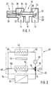
- Figure 1 shows schematically a reversing valve and Figure 2 schematically shows a heater.
- a reversing valve 10 is shown with a housing 12 which has three connections 14, 16 and 18.
- a valve member 20 Arranged within the housing 12 is a valve member 20 which has two closure bodies 22 and 24, the closure body 22 corresponding to a valve seat 26 and the closure body 24 corresponding to a valve seat 28.
- the two closure bodies 22 and 24 are aligned parallel to one another and connected to one another via a rod 30.
- the rod 30 is displaceably held on the side of the closure body (24) in a bearing (32) and extended on the side of the closure body 22 on the side opposite the closure body 24.
- the extension 34 of the rod 30 protrudes into a coil 36 which is attached to the side of the housing 12.
- a spring 38 is inserted between the coil 36 and the closure body 22.
- the elongated rod 30, the coil 36 and the spring 38 together form an actuator 37.
- the distance between the closure bodies 22 and 24 from one another is greater than the distance between the valve seats 26 and 28. In this way, only one closure body 22 or 24 can rest on the valve seat 26 or 28 corresponding to it.
- FIG. 2 shows a heater 40 with a heat exchanger 42, which is supplied with heat by an energy source 44.
- An inner pipeline system 46 through which the heat exchanger 42 is also arranged, leads through the heater 40.
- the pipe system 46 has a branch 48, from which a first pipe branch 50 leads to a heater 40 arranged heat exchanger system 52 and from there to the reversing valve 10.
- a second pipe run 54 leaves the heater and leads to a schematically illustrated heating circuit 56, from there back to the heater 40 and also to the reversing valve 10.
- the heat transfer system 52 is preferably used for domestic water preparation and the heating circuit 56 for space heating.
- a pump 58 which pumps the heating water is also integrated in the inner pipeline system 46 in the heater 40.
- the pump 58 is located between the changeover valve 10 and the heat exchanger 42.
- the connection 14 of the changeover valve 10 is connected to the heating circuit 56, the connection 16 to the heat transfer system 52 and the connection 18 to the input of the pump 58.
- Reversing valve 10 and heater 40 operate as follows:
- thermal energy is transferred to a heating medium via the heat exchanger 42 and pumped through the pipeline system 46 while the pump 58 is running.
- the heating medium flows into the pipeline 54 and through the heating circuit 56 to the connection 14 of the reversing valve 10.
- the closure body 22 is lifted off the valve seat 26, so that the heating medium can flow from the connection 14 to the connection 18. From there the heating medium reaches the inlet of the pump 48 and the circuit is closed.
- the pressure generated by the pump 58 continues in the pipeline string 50 through the heat transfer system 52 to the connection 16 of the reversing valve 10.
- the full pressure of the pump 58 prevails on the connection side 16 of the closure body 24 less the pressure loss within the heat exchanger 42.
- the pump pressure prevails less the pressure loss within the heat exchanger 42, further reduced by the pressure loss within the heating circuit 56 and further reduced by the dynamic pressure generated by the speed of the heating medium.
- the closure body 24 is consequently pressed onto the valve seat 28 by the pressure difference prevailing thereon.
- the electrical coil 36 is deactivated and the extension 34 of the rod 30 is no longer held in the coil 36 and is pulled out of the coil 36 only by the spring.
- the closure body 24 lifts off from the valve seat 28 and the closure body 22 lies on the valve seat 26. The direction of passage from port 14 to port 18 is thus blocked and the passage from port 16 to port 18 is open.
- the heating medium thus flows through the heat transfer system 52. With the pump 58 running is pressed by the prevailing pressure conditions of the closure body 22 on the valve seat 26.
- the pump can also be operated with reduced power during the changeover.
Landscapes
- Engineering & Computer Science (AREA)
- General Engineering & Computer Science (AREA)
- Mechanical Engineering (AREA)
- Physics & Mathematics (AREA)
- Thermal Sciences (AREA)
- Chemical & Material Sciences (AREA)
- Combustion & Propulsion (AREA)
- Multiple-Way Valves (AREA)
- Steam Or Hot-Water Central Heating Systems (AREA)
Abstract
Description
- Die Erfindung betrifft ein Umsteuerventil sowie ein Heizgerät mit einem Umsteuerventil nach den Oberbegriffen der unabhängigen Ansprüche. Derartige Umsteuerventile werden eingesetzt, wenn mehrere Heizkreise von einem Heizgerät versorgt werden, wobei die Heizkreise üblicherweise mit unterschiedlichen Vorlauftemperaturen betrieben werden. Typische Heizkreise hierfür sind die Raumheizung und die Brauchwasserbereitstellung mit einem indirekt beheizten Speicher oder einem Wärmetauscher im Durchlauferhitzerprinzip. Bekannte Umsteuerventile weisen einen Verschlußkörper auf, der mittels eines Betätigungsorgans zwischen zwei Schließstellungen hin und her bewegbar ist. In jeder Schließstellung ist ein Eingang gesperrt und ein weiterer Eingang mit einem Ausgang des Umsteuerventils verbunden. Dabei wird durch den Druck im gesperrten Eingang das Vereschlußglied in Öffnungsrichtung belastet. Hierbei ist unbefriedigend, daß eine hohe Schließkraft benötigt wird, die außerdem vom Pumpendruck abhängt.
- Das erfindungsgemäße Umsteuerventil mit den Merkmalen des Hauptanspruchs haat den Vorteil, daß die am Verschlußkörper des Ventilglieds anliegenden Drücke das sperrende Verschlußglied in Richtung auf den Ventilsitz belastet. Das Betätigungsorgang muß deshalb nur während des Bewegens des Ventilglieds eine hohe Kraft aufbringen.
- Durch die in den Unteransprüchen angegebenen Maßnahmen sind vorteilhafte Weiterbildungen des Umsteuerventils naach dem Hauptanspruch möglich. Eine besonders einfache Ausführung ergibt sich, wenn die Verschlußkörper tellerförmig ausgestaltet und über eine Stange fest miteinander verbunden sind. Die Verschiebebewegung kann dann parallel zur Stange linear oder kreisförmig erfolgen. Eine weitere Vereinfachung ergibt sich, wenn die Verschlußkörper parallel zueinander ausgerichtet sind und die die Verschlußkörper verbindende Stange auch mit dem Betätigungsorgan verbunden ist. Diese Anordnung läßt sich einfach montieren und justieren.
- In vorteilhafterweise ist das Ventilglied elektromagnetisch betätigbar. Dies kann einfach durch die nach außen verlängerte die Verschlußkörper verbindende Stange erfolgen. Durch das Federbelasten des Ventilglieds kann eine definierte Nullstellung vorgegeben werden.
- Das erfindungsgemäße Umsteuerventil ergänzt in vorteilhafterweise ein ein erfindungsgemäßes Heizgerät, wenn die Eingänge des Umsteuerventils mir Rückläufen verschiedener Heizkreise und der Ausgang des Umsteuerventils mit dem Wärmeübertrager des Heizgerätes verbunden ist. Eine das Heizwasser fördernde Pumpe ist dann bevorzugt in Strömungsrichtung gesehen hinter dem Ausgang des Umsteuerventils angeordnet. Damit ist erreicht, daß auf den Verschlußkörper lediglich die um die in den Wärmeübertragern und Heizkreisen abfallenden Druckverluste verminderten Drücke wirken. Dies schont insbesondere die Dichtung innerhalb der Ventilsitze. Ist die Pumpe während des Umschaltvorganges ausgeschaltet, sind die vom Betätigungsorgan aufzuwendenden Kräfte gering, da das Ventilglied nicht gegen den Pumpendruck verschoben werden muß.
- In der Zeichnung ist ein Ausführungsbeispiel dargestellt und in der nachfolgenden Beschreibung näher erläutert. Es zeigen Figur 1 schematisch ein Umsteuerventil und Figur 2 schematisch ein Heizgerät.
- In Figur 1 ist ein Umsteuerventil 10 dargestellt mit einem Gehäuse 12, das drei Anschlüsse 14, 16 und 18 aufweist. Innerhalb des Gehäuses 12 ist ein Ventilglied 20 angeordnet, das zwei Verschlußkörper 22 und 24 aufweist, wobei der Verschlußkörper 22 mit einem Ventilsitz 26 und der Verschlußkörper 24 mit einem Ventilsitz 28 korrespondiert.
- Die beiden Verschlußkörper 22 und 24 sind parallel zueinander ausgerichtet und über eine Stange 30 miteinander verbunden. Die Stange 30 ist auf der Seite des Verschlußkörpers (24) in einem Lager (32) verschiebbeweglich gehalten und auf der Seite des Verschlußkörpers 22 auf der dem Verschlußkörper 24 gegenüberliegenden Seite verlängert. Die Verlängerung 34 der Stange 30 ragt in eine Spule 36, die seitlich am Gehäuse 12 befestigt ist. Zwischen der Spule 36 und dem Verschlußkörper 22 ist eine Feder 38 eingebracht.
- Die verlängerte Stange 30, die Spule 36 und die Feder 38 bilden zusammen ein Betätigungsorgang 37.
- Der Abstand der Verschlußkörper 22 und 24 voneinander ist größer als der Abstand der Ventilsitze 26 und 28 zueinander. Auf diese Weise kann immer nur ein Verschlußkörper 22 oder 24 auf dem mit ihm korrespondierenden Ventilsitz 26 oder 28 aufliegen.
- In Figur 2 ist ein Heizgerät 40 dargestellt, mit einem Wärmeübertrager 42, der von einer Energiequelle 44 mit Wärme versorgt wird. Durch das Heizgerät 40 führt ein inneres Rohrleitungssystem 46, innerhalb dem auch der Wärmeübertrager 42 angeordnet ist. Das Rohrleitungssystem 46 weist einen Abzweig 48 auf, von dem ein erster Rohrleitungsstrang 50 zu einem Heizgerät 40 angeordneten Wärmeübertragersystem 52 und von dort zum Umsteuerventil 10 führt. Ein zweiter Rohrleitungsstrang 54 verläßt das Heizgerät und führt zu einem schematisch dargestellten Heizkreis 56, von dort zurück zum Heizgerät 40 und ebenfalls zum Umsteuerventil 10. Das Wärmeübertragersystem 52 dient vorzugsweise zur Brauchwasserbereitung und der Heizkreis 56 der Raumheizung.
- Im Heizgerät 40 ist ferner eine das Heizwasser fördernde Pumpe 58 in das innere Rohrleitungssystem 46 eingebunden. Die Pumpe 58 liegt zwischen dem Umsteuerventil 10 und dem Wärmeübertrager 42. Der Anschluß 14 des Umsteuerventils 10 ist mit dem Heizkreis 56, der Anschluß 16 mit dem Wärmeübertragersystem 52 und der Anschluß 18 mit dem Eingang der Pumpe 58 verbunden.
- Umsteuerventil 10 und Heizgerät 40 arbeiten wie folgt:
- Während des Betriebs des Heizgeräts 40 wird über den Wärmeübertrager 42 Wärmeenergie auf ein Heizmedium übertragen und bei laufender Pumpe 58 über das Rohrleitungssystem 46 umgepumpt. In der in Figur 1 gezeigten Stellung fließt das Heizmedium in den Rohrleitungsstrang 54 und durch den Heizkreis 56 zum Anschluß 14 des Umsteuerventils 10. Der Verschlußkörper 22 ist vom Ventilsitz 26 abgehoben, so daß das Heizmedium vom Anschluß 14 zum Anschluß 18 strömen kann. Von dort gelangt das Heizmedium zum Eingang der Pumpe 48 und der Kreislauf ist geschlossen. Der von der Pumpe 58 erzeugte Druck setzt sich im Rohrleitungsstrang 50 durch das Wärmeübertragersystem 52 bis zum Anschluß 16 des Umsteuerventils 10 fort. Da der Verschlußkörper 24 auf dem Ventilsitz 28 aufliegt herrscht auf der Anschlußseite 16 des Verschlußkörpers 24 der volle Druck der Pumpe 58 vermindert um den Druckverlust innerhalb des Wärmeübertragers 42. Auf der gegenüberliegenden Seite herscht der Pumpendruck vermindert um den Druckverlust innerhalb des Wärmeübertragers 42, weiter vermindert um den Druckverlust innerhalb des Heizkreises 56 und weiter vermindert durch den durch die Geschwindigkeit des Heizmediums erzeugten Staudruck. Der Verschlußkörper 24 wird folglich durch die auf ihn herrschende Druckdifferenz auf den Ventilsitz 28 gepreßt.
- Wird Wärmeenergie im Wärmeübertragersystem 52 benötigt, wird die elektrische Spule 36 deaktiviert und die Verlängerung 34 der Stange 30 nicht mehr in der Spule 36 gehalten und nur durch die Feder aus der Spule 36 herausgezogen. Der Verschlußkörper 24 hebt sich vom Ventilsitz 28 ab und der Verschlußkörper 22 legt sich auf den Ventilsitz 26 auf. Damit ist die Durchgangsrichtung vom Anschluß 14 zum Anschluß 18 gesperrt und der Durchgang vom Anschluß 16 auf den Anschluß 18 geöffnet. Das Heizungsmedium strömt somit durch das Wärmeübertragersystem 52. Bei laufender Pumpe 58 wird durch die herrschenden Druckverhätnisse der Verschlußkörper 22 auf den Ventilsitz 26 gepreßt.
- Bei günstiger Druckverhältnissen ist eine zusätzliche Kraft zur Abdichtung des gesperrten Ventilsitzes nicht notwendig.
- Wird vor Beginn eines Umschaltvorganges des Umschaltventils 10 die Pumpe 58 abgeschaltet, sind nur sehr geringe Bewegungskräfte, die hauptsächlich durch die Feder 38 und die Reibungskräfte innerhalb des Lagers 30 bedingt sind, vom Betätigungsorgan 37 aufzubringen. Dieses kann dann entsprechend kleiner ausgelegt sein.
- Sofern es aufgrund der Pumpen oder Heiznetzauslegung zweckmäßig ist, kann die Pumpe auch während des Umschaltens mit reduzierter Leistung betrieben werden.
- Statt einer Feder 38 ist es möglich, ein Magnetsystem zu verwenden. An der Spule 36 und der Stange 30 müßten dann zwei sich gegenseitig abstoßende Magnete befestigt sein.
Claims (10)
- Umsteuerventil zum Steuern von Gasen oder Flüssigkeiten, insbesondere eines Heizmediums, mit mindestens drei Anschlüssen, von denen mindestens zwei Eingänge und mindestens einer ein Ausgang sind und mit einem, durch ein Betätigungsorgan bewegbaren Ventilglied, das je nach Stellung den Durchgang zwischen zwei Anschlüssen ermöglicht, dadurch gekennzeichnet, daß das Ventilglied 20 mindestens zwei miteinander verbundene Verschlußkörper (22, 24) aufweist, die jeder mit einem Ventilsitz (26, 28) zusammenwirken und daß jeder Ventilsitz (26, 28) in Strömungsrichtung gesehen hinter dem entsprechenden Verschlußkörper (22, 24) liegt.
- Umsteuerventil nach Anspruch 1 oder 2, dadurch gekennzeichnet, daß die Verschlußkörper (22, 24) tellerförmig ausgestaltet und über eine Stange (30) oder dergleichen fest miteinander verbunden sind.
- Umsteuerventil nach Anspruch 2, dadurch gekennzeichnet, daß die tellerförmigen Verschlußkörper (22, 24) parallel zueinander ausgerichtet sind und daß die Stange (30) mit dem Betätigungsorgang (37) verbunden ist.
- Umsteuerventil nach einem der Ansprüche 1 bis 3, dadurch gekennzeichnet, daß die Ventilsitze (26, 28) auf einander zugewandten Seiten der Verschlußkörper (22, 24) liegen und daß der Abstand der Verschlußkörper (22, 24) voneinander größer ist als der Abstand der Ventilsitze.
- Umsteuerventil nach einem der Ansprüche 1 bis 4, dadurch gekennzeichnet, daß das Ventilglied (20) elektromagnetisch betätigbar ist.
- Umsteuerventil nach einem der Ansprüche 1 bis 5, dadurch gekennzeichnet, daß das Ventilglied (20) federbelastet ist.
- Heizgerät für mindestens zwei Heizkreise, insbesondere für die Erwärmung von Brauchwasser und die Raumheizung, mit einem Wärmeübertrager und mit einem Umsteuerventil nach einem der Ansprüche 1 bis 6, mit dem zwischen den Heizkreisen umgeschaltet werden kann, dadurch gekennzeichnet, daß die Eingänge des Umsteuerventils mit den Rückläufen der Heizkreise (56, 52) und der Ausgang (18) mit dem Wärmeübertrager (42) verbunden ist.
- Heizgerät nach Anspruch 7, dadurch gekennzeichnet, daß eine des Heizwasser fördernde Pumpe (58) in Strömungsrichtung gesehen nach dem Umsteuerventil (10) angeordnet ist.
- Heizgerät nach Anspruch 8, dadurch gekennzeichnet, daß der Ausgang des Umsteuerventils (10) mit dem Eingang der Pumpe (58) verbunden ist.
- Heizgerät nach Anspruch 8 der 9, dadurch gekennzeichnet, daß die Pumpe (58) während eines Schaltvorgangs des Umsteuerventils (10) abgeschaltet oder mit reduzierter Leistung betrieben ist.
Applications Claiming Priority (2)
| Application Number | Priority Date | Filing Date | Title |
|---|---|---|---|
| DE19540816A DE19540816A1 (de) | 1995-11-02 | 1995-11-02 | Umsteuerventil sowie Heizgerät mit einem Umsteuerventil |
| DE19540816 | 1995-11-02 |
Publications (3)
| Publication Number | Publication Date |
|---|---|
| EP0771978A2 true EP0771978A2 (de) | 1997-05-07 |
| EP0771978A3 EP0771978A3 (de) | 1997-07-09 |
| EP0771978B1 EP0771978B1 (de) | 2001-12-19 |
Family
ID=7776427
Family Applications (1)
| Application Number | Title | Priority Date | Filing Date |
|---|---|---|---|
| EP96116210A Expired - Lifetime EP0771978B1 (de) | 1995-11-02 | 1996-10-10 | Heizgerät mit einem Umsteuerventil |
Country Status (2)
| Country | Link |
|---|---|
| EP (1) | EP0771978B1 (de) |
| DE (2) | DE19540816A1 (de) |
Cited By (3)
| Publication number | Priority date | Publication date | Assignee | Title |
|---|---|---|---|---|
| DE10058516A1 (de) * | 2000-11-24 | 2002-05-29 | Obrist Engineering Gmbh Lusten | Mehrwegeventil |
| EP0994311A3 (de) * | 1998-10-14 | 2002-09-18 | Fugas Spa | Hydraulische Baugruppe für Heizungs-und Heisswasseranlagen , mit einem Heisswasserspeicher |
| CN106801748A (zh) * | 2016-12-16 | 2017-06-06 | 无锡锡通工程机械有限公司 | 一种干砂仓除湿除尘系统用远程控制电动转换阀 |
Families Citing this family (4)
| Publication number | Priority date | Publication date | Assignee | Title |
|---|---|---|---|---|
| DE10100886A1 (de) * | 2001-01-11 | 2002-08-14 | Bosch Gmbh Robert | Umsteuerventil für eine Heizungsanlage |
| DE10111886A1 (de) * | 2001-03-13 | 2002-10-02 | Eberspaecher J Gmbh & Co | Abgaskühlelement für einen Abgasstrang einer Brennkraftmaschine |
| DE10222936A1 (de) * | 2002-05-24 | 2003-12-04 | Zahnradfabrik Friedrichshafen | Proportional-Druckregelventil |
| EP3156659B1 (de) * | 2015-10-12 | 2020-09-16 | Grundfos Holding A/S | Pumpenaggregat und hydraulisches system |
Family Cites Families (6)
| Publication number | Priority date | Publication date | Assignee | Title |
|---|---|---|---|---|
| DE7235386U (de) * | 1972-12-14 | Lins A | Umsteuerventil | |
| DE242681C (de) * | ||||
| FR1020134A (fr) * | 1950-06-13 | 1953-02-02 | Perfectionnements aux vannes à trois voies pour fluides sous pression | |
| AT394771B (de) * | 1989-11-07 | 1992-06-25 | Vaillant Gmbh | Verfahren und einrichtung zur durchfuehrung des verfahrens zum sofortigen zapfen von warmem brauchwasser |
| IT1244296B (it) * | 1990-07-09 | 1994-07-08 | Giuseppe Fugazza | Complesso valvolare per impianti di riscaldamento |
| AT399941B (de) * | 1993-06-16 | 1995-08-25 | Vaillant Gmbh | Einrichtung bei einer heizungsanlage |
-
1995
- 1995-11-02 DE DE19540816A patent/DE19540816A1/de not_active Withdrawn
-
1996
- 1996-10-10 DE DE59608493T patent/DE59608493D1/de not_active Expired - Fee Related
- 1996-10-10 EP EP96116210A patent/EP0771978B1/de not_active Expired - Lifetime
Cited By (4)
| Publication number | Priority date | Publication date | Assignee | Title |
|---|---|---|---|---|
| EP0994311A3 (de) * | 1998-10-14 | 2002-09-18 | Fugas Spa | Hydraulische Baugruppe für Heizungs-und Heisswasseranlagen , mit einem Heisswasserspeicher |
| DE10058516A1 (de) * | 2000-11-24 | 2002-05-29 | Obrist Engineering Gmbh Lusten | Mehrwegeventil |
| DE10058516B4 (de) * | 2000-11-24 | 2006-09-07 | Audi Ag | Mehrwegeventil |
| CN106801748A (zh) * | 2016-12-16 | 2017-06-06 | 无锡锡通工程机械有限公司 | 一种干砂仓除湿除尘系统用远程控制电动转换阀 |
Also Published As
| Publication number | Publication date |
|---|---|
| EP0771978B1 (de) | 2001-12-19 |
| EP0771978A3 (de) | 1997-07-09 |
| DE59608493D1 (de) | 2002-01-31 |
| DE19540816A1 (de) | 1997-05-07 |
Similar Documents
| Publication | Publication Date | Title |
|---|---|---|
| DE3614425A1 (de) | Elektromagnetische mehrfunktions-absperrorgananordnung | |
| EP3077712B1 (de) | Magentventil | |
| DE112007001455T5 (de) | Strömungsmittelgesteuertes Ventil | |
| DE10023329A1 (de) | Ventil | |
| DE102012013594A1 (de) | Leitungssystem zum Transport von Flüssigkeiten | |
| EP0771978A2 (de) | Umsteuerventil sowie Heizgerät mit einem Umsteuerventil | |
| EP0529353B1 (de) | Gastherme | |
| DE102004057873B4 (de) | Sitzventil | |
| DE2241504B2 (de) | Zentralheizungssystem mit Dreiwegeventil zum Umsteuern des Wärmemediums zu Heizkörpern oder zu einem Brauchwasser-Wärmetauscher | |
| EP0401468A2 (de) | Ventilanordnung zum gleichzeitigen Öffnen und Absperren zweier getrennter Zuleitungen für flüssige oder gasförmige Medien | |
| EP1650434A2 (de) | Mehrstufiger Kolbenverdichter mit reduzierter Leistungsaufnahme im Leerlauf | |
| DE19824630B4 (de) | Ventilkombination aus einem Membranregler, einer Drossel und einem Regelventil | |
| DE3822830A1 (de) | Eigenmediumbetaetigtes, durch ein bistabiles magnetventil servogesteuertes ventil fuer fluessige medien | |
| EP2184520B1 (de) | Ventil mit einer Einrichtung gegen Wasserschlag | |
| EP0988163A1 (de) | Magnetventil für eine flüssigkeitsgeregelte heiz- und/oder kühlanlage | |
| DE4127822A1 (de) | Gastherme | |
| DE29611368U1 (de) | Heizgerät mit einem Umsteuerventil | |
| EP1754916B1 (de) | Ventil mit Piezoelement | |
| DE1650504A1 (de) | Ventileinheit | |
| DE4039644A1 (de) | Ueberstroemventil | |
| DE2829528C2 (de) | Kombinierte Überdruck-Spülventilanordnung für ein hydrostatisches Getriebe, insbesondere zum Antrieb von Fahrzeugen | |
| DE303768C (de) | ||
| AT230519B (de) | Vorrichtung zur Verhinderung des Nachspritzens von Öl aus der Düse bei Druckölbrennern | |
| WO2011113573A1 (de) | Stellantrieb für ein gasventil | |
| WO2018121811A1 (de) | Regelarmatur zur regelung des differenzdruckes und/oder des volumenstromes |
Legal Events
| Date | Code | Title | Description |
|---|---|---|---|
| PUAI | Public reference made under article 153(3) epc to a published international application that has entered the european phase |
Free format text: ORIGINAL CODE: 0009012 |
|
| AK | Designated contracting states |
Kind code of ref document: A2 Designated state(s): DE FR GB IT NL |
|
| PUAL | Search report despatched |
Free format text: ORIGINAL CODE: 0009013 |
|
| AK | Designated contracting states |
Kind code of ref document: A3 Designated state(s): DE FR GB IT NL |
|
| 17P | Request for examination filed |
Effective date: 19980109 |
|
| 17Q | First examination report despatched |
Effective date: 19991202 |
|
| GRAG | Despatch of communication of intention to grant |
Free format text: ORIGINAL CODE: EPIDOS AGRA |
|
| RIC1 | Information provided on ipc code assigned before grant |
Free format text: 7F 16K 11/048 A, 7F 24D 3/08 B, 7F 24D 19/10 B |
|
| RTI1 | Title (correction) |
Free format text: HEATING DEVICE WITH A REVERSIBLE VALVE |
|
| RIC1 | Information provided on ipc code assigned before grant |
Free format text: 7F 16K 11/048 A, 7F 24D 3/08 B, 7F 24D 19/10 B |
|
| RTI1 | Title (correction) |
Free format text: HEATING DEVICE WITH A REVERSIBLE VALVE |
|
| RIC1 | Information provided on ipc code assigned before grant |
Free format text: 7F 16K 11/048 A, 7F 24D 3/08 B, 7F 24D 19/10 B |
|
| RTI1 | Title (correction) |
Free format text: HEATING DEVICE WITH A REVERSIBLE VALVE |
|
| GRAG | Despatch of communication of intention to grant |
Free format text: ORIGINAL CODE: EPIDOS AGRA |
|
| GRAH | Despatch of communication of intention to grant a patent |
Free format text: ORIGINAL CODE: EPIDOS IGRA |
|
| GRAH | Despatch of communication of intention to grant a patent |
Free format text: ORIGINAL CODE: EPIDOS IGRA |
|
| GRAA | (expected) grant |
Free format text: ORIGINAL CODE: 0009210 |
|
| AK | Designated contracting states |
Kind code of ref document: B1 Designated state(s): DE FR GB IT NL |
|
| REG | Reference to a national code |
Ref country code: GB Ref legal event code: IF02 |
|
| REF | Corresponds to: |
Ref document number: 59608493 Country of ref document: DE Date of ref document: 20020131 |
|
| GBT | Gb: translation of ep patent filed (gb section 77(6)(a)/1977) |
Effective date: 20020311 |
|
| PGFP | Annual fee paid to national office [announced via postgrant information from national office to epo] |
Ref country code: GB Payment date: 20020919 Year of fee payment: 7 |
|
| PGFP | Annual fee paid to national office [announced via postgrant information from national office to epo] |
Ref country code: FR Payment date: 20021018 Year of fee payment: 7 |
|
| PGFP | Annual fee paid to national office [announced via postgrant information from national office to epo] |
Ref country code: NL Payment date: 20021022 Year of fee payment: 7 |
|
| PLBE | No opposition filed within time limit |
Free format text: ORIGINAL CODE: 0009261 |
|
| STAA | Information on the status of an ep patent application or granted ep patent |
Free format text: STATUS: NO OPPOSITION FILED WITHIN TIME LIMIT |
|
| 26N | No opposition filed | ||
| PG25 | Lapsed in a contracting state [announced via postgrant information from national office to epo] |
Ref country code: GB Free format text: LAPSE BECAUSE OF NON-PAYMENT OF DUE FEES Effective date: 20031010 |
|
| PGFP | Annual fee paid to national office [announced via postgrant information from national office to epo] |
Ref country code: DE Payment date: 20031215 Year of fee payment: 8 |
|
| PG25 | Lapsed in a contracting state [announced via postgrant information from national office to epo] |
Ref country code: NL Free format text: LAPSE BECAUSE OF NON-PAYMENT OF DUE FEES Effective date: 20040501 |
|
| GBPC | Gb: european patent ceased through non-payment of renewal fee |
Effective date: 20031010 |
|
| PG25 | Lapsed in a contracting state [announced via postgrant information from national office to epo] |
Ref country code: FR Free format text: LAPSE BECAUSE OF NON-PAYMENT OF DUE FEES Effective date: 20040630 |
|
| NLV4 | Nl: lapsed or anulled due to non-payment of the annual fee |
Effective date: 20040501 |
|
| REG | Reference to a national code |
Ref country code: FR Ref legal event code: ST |
|
| PG25 | Lapsed in a contracting state [announced via postgrant information from national office to epo] |
Ref country code: DE Free format text: LAPSE BECAUSE OF NON-PAYMENT OF DUE FEES Effective date: 20050503 |
|
| PG25 | Lapsed in a contracting state [announced via postgrant information from national office to epo] |
Ref country code: IT Free format text: LAPSE BECAUSE OF NON-PAYMENT OF DUE FEES;WARNING: LAPSES OF ITALIAN PATENTS WITH EFFECTIVE DATE BEFORE 2007 MAY HAVE OCCURRED AT ANY TIME BEFORE 2007. THE CORRECT EFFECTIVE DATE MAY BE DIFFERENT FROM THE ONE RECORDED. Effective date: 20051010 |