EP0770008B1 - Antriebsvorrichtung für landwirtschaftliche erntemaschinen - Google Patents
Antriebsvorrichtung für landwirtschaftliche erntemaschinen Download PDFInfo
- Publication number
- EP0770008B1 EP0770008B1 EP95928448A EP95928448A EP0770008B1 EP 0770008 B1 EP0770008 B1 EP 0770008B1 EP 95928448 A EP95928448 A EP 95928448A EP 95928448 A EP95928448 A EP 95928448A EP 0770008 B1 EP0770008 B1 EP 0770008B1
- Authority
- EP
- European Patent Office
- Prior art keywords
- drive
- coupling
- arrangement
- power take
- devices
- Prior art date
- Legal status (The legal status is an assumption and is not a legal conclusion. Google has not performed a legal analysis and makes no representation as to the accuracy of the status listed.)
- Expired - Lifetime
Links
- 241001124569 Lycaenidae Species 0.000 title description 8
- 230000008878 coupling Effects 0.000 claims description 14
- 238000010168 coupling process Methods 0.000 claims description 14
- 238000005859 coupling reaction Methods 0.000 claims description 14
- 238000003306 harvesting Methods 0.000 claims description 10
- 238000002485 combustion reaction Methods 0.000 claims description 4
- 230000005540 biological transmission Effects 0.000 description 5
- 238000010276 construction Methods 0.000 description 2
- 238000005520 cutting process Methods 0.000 description 2
- 238000003825 pressing Methods 0.000 description 2
- 206010010774 Constipation Diseases 0.000 description 1
- 230000000295 complement effect Effects 0.000 description 1
- 239000004459 forage Substances 0.000 description 1
- 230000007257 malfunction Effects 0.000 description 1
- 238000004519 manufacturing process Methods 0.000 description 1
- 238000000034 method Methods 0.000 description 1
- 230000002093 peripheral effect Effects 0.000 description 1
- 238000007873 sieving Methods 0.000 description 1
- 238000003860 storage Methods 0.000 description 1
- 230000001960 triggered effect Effects 0.000 description 1
Images
Classifications
-
- B—PERFORMING OPERATIONS; TRANSPORTING
- B60—VEHICLES IN GENERAL
- B60K—ARRANGEMENT OR MOUNTING OF PROPULSION UNITS OR OF TRANSMISSIONS IN VEHICLES; ARRANGEMENT OR MOUNTING OF PLURAL DIVERSE PRIME-MOVERS IN VEHICLES; AUXILIARY DRIVES FOR VEHICLES; INSTRUMENTATION OR DASHBOARDS FOR VEHICLES; ARRANGEMENTS IN CONNECTION WITH COOLING, AIR INTAKE, GAS EXHAUST OR FUEL SUPPLY OF PROPULSION UNITS IN VEHICLES
- B60K17/00—Arrangement or mounting of transmissions in vehicles
- B60K17/28—Arrangement or mounting of transmissions in vehicles characterised by arrangement, location, or type of power take-off
-
- Y—GENERAL TAGGING OF NEW TECHNOLOGICAL DEVELOPMENTS; GENERAL TAGGING OF CROSS-SECTIONAL TECHNOLOGIES SPANNING OVER SEVERAL SECTIONS OF THE IPC; TECHNICAL SUBJECTS COVERED BY FORMER USPC CROSS-REFERENCE ART COLLECTIONS [XRACs] AND DIGESTS
- Y10—TECHNICAL SUBJECTS COVERED BY FORMER USPC
- Y10T—TECHNICAL SUBJECTS COVERED BY FORMER US CLASSIFICATION
- Y10T74/00—Machine element or mechanism
- Y10T74/19—Gearing
- Y10T74/19023—Plural power paths to and/or from gearing
- Y10T74/19033—Fluid drive divides or combines alternate paths
Definitions
- the invention relates to a drive device for an agricultural Vehicle according to the preamble of claim 1.
- Such a drive device is known from GB-A 912,109.
- the hydrostat hydraulic pump and hydraulic motor
- the force-diverting device is also in the transmission integrated, whereby a clutch is provided between the drive source and the transmission is.
- it is an agricultural one Tractor with the tractor-specific requirements for the drive gear.
- the invention has for its object a drive device for a Provide agricultural harvester, the drive device should be structurally simple and a power branch Provides device, the speed of which depends on the driving speed should vary.
- the vehicle as a self-driving Harvester is designed and the power branching device for Drive other devices of the harvester that the hydraulic pump is non-positively connected to the internal combustion engine that the force-diverting device behind the hydraulic motor and in front of the reduction gear is arranged and that the coupling between the force-diverting device and the reduction gear installed is.
- This configuration makes a force-diverting device for Provided with the devices of the harvester proportional to the driving speed Can be driven so that the Processing speed of the other devices of the driving speed the harvester is adjusted.
- the clutch can be actuated, for example when the machine is at a standstill to let the other devices run, so that with standstill the machine continues the processing process.
- the power branch Device can also in the direction of the other devices be connected at least one gear. There may also be others here force-diverting devices, further couplings or flywheels connect.
- the force-absorbing device is as Angular gear trained. This is a problem-free and Given a structurally simple implementable branching device.
- this angular gear is essentially in the elongated drive device (in particular below a Operator's platform of the agricultural harvester), which is located in the drive axle area located, easy to integrate and allows a direct Drive the other devices.
- the drive source after opening the in the drive train arranged clutch at least for a short time Reversal of direction of rotation formed.
- This has the advantage that after the Drive of the harvester has been switched off, the drive of the others Devices is reversed so that, for example, in the case of a Malfunction or a blockage of one of the other devices this Disruption or constipation caused by reversing the direction of rotation can be eliminated.
- This can be done simply by pressing a button, for example are triggered by an operator of the harvester.
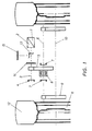
- FIG. 1 shows a drive device designed according to the invention for an agricultural harvesting machine.
- This drive device has a hydraulic pump 1 and a hydraulic motor 2, which are shown schematically and wherein the hydraulic pump 1 is driven by an internal combustion engine, not shown.
- the hydraulic motor 2 acts on the one hand via a shaft 3 on a parking brake 4 which can be actuated when the harvesting machine is at a standstill.
- a gear 5 is driven via the shaft 3, which is designed as a simple reduction gear in the manner according to the invention.
- This transmission 5 acts on the output side on a shaft 6 on which service brakes 7 (for example disc brakes which can be actuated during the operation of the harvesting machine) are arranged, a differential 8 also being arranged in the shaft 6, which decouples different peripheral speeds of the drive wheels.
- the shaft 6 acts on the end on a further gear 9 (also a simple reduction gear), this gear 9 acting on the output side on a shaft 10 on which the drive wheels in the form of rims 11 and tires 12 are arranged.
- a force-diverting device in the form of an angular gear 13 is arranged in the drive train.
- the angular gear 13 is arranged in the drive train with a clutch 14, which in particular acts as a force fit.
- the drive of the hydraulic motor 2 on the drive wheels (rims 11 and tires 12) can be switched off or on.
- the angular gear 13 is followed by a coupling 15, which acts in particular with a form fit, via which the further devices (not shown) can be switched on and off.
- the drive of the agricultural harvesting machine and the drive of the further devices integrated in the agricultural harvesting machine can thus be operated independently or depending on the application condition.
- the force-branching device angular gear 13
- the force-branching device is arranged directly near the hydraulic motor 2 or on the latter.
- the drive device designed according to the invention is general Use in agricultural harvesters.
- a special Fields of application are combine harvesters, with the other devices of the combine, for example threshing, shaking, sieving, Cutting and receiving devices.
- Another field of application are harvesting machines for green fodder processing, which then with the other devices for cutting, conveying, processing, Press and storage devices.
- the third field of application is as Harvesters called self-propelled big balers, being it the other devices are related to admission or Pressing and dispensing devices for the big bales acts.
- the configuration according to the invention is self-evident not limited to the three mentioned harvesting machines, but can also be used in other areas of application (generally agricultural or construction Vehicles) and other types of agricultural Harvesters (e.g. forage harvesters) can be expanded.
Landscapes
- Engineering & Computer Science (AREA)
- Chemical & Material Sciences (AREA)
- Combustion & Propulsion (AREA)
- Transportation (AREA)
- Mechanical Engineering (AREA)
- Harvester Elements (AREA)
- Arrangement And Driving Of Transmission Devices (AREA)
Description
Claims (5)
- Antriebsvorrichtung für ein landwirtschaftliches Fahrzeug, dessen auf die Treibräder (11, 12) wirkender Antriebsstrang eine als Brennkraftmaschine ausgebildete Antriebsquelle, eine Kupplung (14) zur Unterbrechung des Kraftflußes, eine Hydropumpe (1) mit angetriebenem Hydromotor (2) [Hydrostat], zumindest ein Untersetzungsgetriebe (5) und ein zwischen den Treibrädern (11, 12) wirkendes Differential (8) sowie eine kraftabzweigende Vorrichtung aufweist,
dadurch gekennzeichnet, daß das Fahrzeug als selbstfahrende Erntemaschine ausgebildet ist und die kraftabzweigende Vorrichtung zum Antrieb weiterer Vorrichtungen der Erntemaschine dient,daß die Hydropumpe (1) mit der Brennkraftmaschine kraftschlüssig verbunden ist,daß die kraftabzweigende Vorrichtung hinter dem Hydromotor (2) und vor dem Untersetzungsgetriebe (5) angeordnet ist unddaß die Kupplung (14) zwischen der kraftabzweigenden Vorrichtung und dem Untersetzungsgetriebe (5) eingebaut ist. - Antriebsvorrichtung nach Anspruch 1,
dadurch gekennzeichnet, daß der kraftabzweigenden Vorrichtung eine Kupplung (15) nachgeschaltet ist, mit der die weiteren Vorrichtungen zubeziehungsweise abschaltbar sind. - Antriebsvorrichtung nach Anspruch 1 oder 2,
dadurch gekennzeichnet, daß die in dem Antriebsstrang angeordnete Kupplung (14) als kraftschlüssig wirkende Kupplung und die vor den weiteren Vorrichtungen angeordnete Kupplung (15) als formschlüssig wirkende Kupplung ausgebildet ist. - Antriebsvorrichtung nach einem der vorhergehenden Ansprüche,
dadurch gekennzeichnet, daß die kraftabzweigende Vorrichtung als Winkelgetriebe (13) ausgebildet ist. - Antriebsvorrichtung nach einem der vorhergehenden Ansprüche,
dadurch gekennzeichnet, daß in dem Antriebsstrang Bremsen [wie zum Beispiel Feststell- (4) und/oder Betriebsbremsen (7)] vorgesehen sind.
Applications Claiming Priority (3)
| Application Number | Priority Date | Filing Date | Title |
|---|---|---|---|
| DE4424442A DE4424442A1 (de) | 1994-07-12 | 1994-07-12 | Antriebsvorrichtung für landwirtschaftliche Erntemaschinen |
| DE4424442 | 1994-07-12 | ||
| PCT/EP1995/002714 WO1996001746A1 (de) | 1994-07-12 | 1995-07-12 | Antriebsvorrichtung für landwirtschaftliche erntemaschinen |
Publications (2)
| Publication Number | Publication Date |
|---|---|
| EP0770008A1 EP0770008A1 (de) | 1997-05-02 |
| EP0770008B1 true EP0770008B1 (de) | 1998-04-22 |
Family
ID=6522869
Family Applications (1)
| Application Number | Title | Priority Date | Filing Date |
|---|---|---|---|
| EP95928448A Expired - Lifetime EP0770008B1 (de) | 1994-07-12 | 1995-07-12 | Antriebsvorrichtung für landwirtschaftliche erntemaschinen |
Country Status (4)
| Country | Link |
|---|---|
| US (1) | US5718299A (de) |
| EP (1) | EP0770008B1 (de) |
| DE (2) | DE4424442A1 (de) |
| WO (1) | WO1996001746A1 (de) |
Families Citing this family (3)
| Publication number | Priority date | Publication date | Assignee | Title |
|---|---|---|---|---|
| CN101036067A (zh) * | 2004-10-08 | 2007-09-12 | 皇家飞利浦电子股份有限公司 | 提取流信号的超声成像方法 |
| CN102848914A (zh) * | 2012-09-12 | 2013-01-02 | 青岛科瑞特激光设备有限公司 | 一种液压无级变速驱动桥总成 |
| CN103072478A (zh) * | 2013-01-16 | 2013-05-01 | 青岛科瑞特激光设备有限公司 | 一种应用于大型自走式联合收割机的驱动桥总成 |
Citations (2)
| Publication number | Priority date | Publication date | Assignee | Title |
|---|---|---|---|---|
| US2158483A (en) * | 1937-06-30 | 1939-05-16 | Spicer Mfg Corp | Power take-off for motor vehicles |
| GB912109A (en) * | 1960-06-03 | 1962-12-05 | Linde Eismasch Ag | Improvements in or relating to engine drive change-speed transmission systems |
Family Cites Families (9)
| Publication number | Priority date | Publication date | Assignee | Title |
|---|---|---|---|---|
| GB887551A (en) * | 1959-10-09 | 1962-01-17 | Linde Eismasch Ag | Improvements in vehicle power-trnasmission arrangements |
| DE2222835A1 (de) * | 1972-05-10 | 1973-11-29 | Kloeckner Humboldt Deutz Ag | Fahrzeug, insbesondere land- und/oder bauwirtschaftlich nutzbares motorfahrzeug mit einem zapfwellenantrieb |
| DE3109409A1 (de) * | 1981-03-12 | 1982-09-30 | Claas Ohg, 4834 Harsewinkel | Mehrzweckfahrzeug |
| ZA849305B (en) * | 1984-01-13 | 1985-07-31 | Zahnradfabrik Friedrichshafen | Multi-axle vehicle with individual wheel drives |
| CS245163B1 (en) * | 1984-04-02 | 1986-08-14 | Zbynek Albrecht | Small tractor's tools driving mechanism |
| US4691802A (en) * | 1984-07-10 | 1987-09-08 | Kubota, Ltd. | Agricultural tractor |
| US4727759A (en) * | 1985-08-27 | 1988-03-01 | Kanzaki Kokyukoki Mfg. Co. Ltd. | Power transmission mechanism for a tractor |
| US4838011A (en) * | 1988-02-19 | 1989-06-13 | Deere & Company | Fluid actuated clutch having fluid slip fitting safety interlock |
| FR2713155B1 (fr) * | 1993-12-01 | 1996-01-26 | Manitou Bf | Chariot élévateur à bras télescopique. |
-
1994
- 1994-07-12 DE DE4424442A patent/DE4424442A1/de not_active Withdrawn
-
1995
- 1995-07-12 US US08/765,044 patent/US5718299A/en not_active Expired - Fee Related
- 1995-07-12 DE DE59502003T patent/DE59502003D1/de not_active Expired - Fee Related
- 1995-07-12 EP EP95928448A patent/EP0770008B1/de not_active Expired - Lifetime
- 1995-07-12 WO PCT/EP1995/002714 patent/WO1996001746A1/de not_active Ceased
Patent Citations (2)
| Publication number | Priority date | Publication date | Assignee | Title |
|---|---|---|---|---|
| US2158483A (en) * | 1937-06-30 | 1939-05-16 | Spicer Mfg Corp | Power take-off for motor vehicles |
| GB912109A (en) * | 1960-06-03 | 1962-12-05 | Linde Eismasch Ag | Improvements in or relating to engine drive change-speed transmission systems |
Also Published As
| Publication number | Publication date |
|---|---|
| DE59502003D1 (de) | 1998-05-28 |
| WO1996001746A1 (de) | 1996-01-25 |
| DE4424442A1 (de) | 1996-01-18 |
| EP0770008A1 (de) | 1997-05-02 |
| US5718299A (en) | 1998-02-17 |
Similar Documents
| Publication | Publication Date | Title |
|---|---|---|
| DE69727191T2 (de) | System zur Steuerung und Überwachung der Zapfwelle | |
| EP1862057B1 (de) | Vorsatzgerät zum Ernten von stängeligem Erntegut | |
| EP1046334B1 (de) | Antriebseinrichtung der Förder- und/oder Gutbearbeitungsvorrichtung einer Erntemaschine | |
| EP0860106B1 (de) | Maschine zum reihenunabhängigen Mähen von Mais und dgl. stengelartigem Erntegut | |
| EP2853431B1 (de) | Zapfwellengetriebe für eine landwirtschaftliche Arbeitsmaschine | |
| EP3906770B1 (de) | Antriebssystem für eine selbstfahrende erntemaschine | |
| DE10243527A1 (de) | Sicherheitseinrichtung einer Erntemaschine | |
| DE2246856B2 (de) | Antriebsvorrichtung fuer einen selbstfahrenden feldhaecksler | |
| DE1855336U (de) | Ackerschlepper mit einer zapfenwelle. | |
| DE102019213353A1 (de) | Antriebssystem für eine Erntemaschine | |
| DE102008009447B4 (de) | Selbstfahrende landwirtschaftliche Erntemaschine mit zwei Verbrennungsmotoren | |
| DE102009028056A1 (de) | Selbstfahrende Erntemaschine | |
| EP0025848B1 (de) | Selbstfahrende Maschine mit Arbeitsgeräten, insbesondere Landmaschine | |
| DE202011001967U1 (de) | Landwirtschaftliche Maschine | |
| AT397596B (de) | Mähmaschine | |
| EP0770008A1 (de) | Antriebsvorrichtung für landwirtschaftliche erntemaschinen | |
| DE905930C (de) | Schlepper, insbesondere Ackerschlepper | |
| EP1566090B1 (de) | Maschine zum Mähen von stängelartigem Erntegut | |
| DE3439710A1 (de) | Mehrzweckgeraetetraeger | |
| DE2735598A1 (de) | Standgetriebe fuer landwirtschaftliche maschinen | |
| DD237778A5 (de) | Hilfsantriebsvorrichtung fuer den ruecklauf des antriebes von arbeitsorganen eines maehdreschers | |
| DE1131519B (de) | Kraftfahrzeug-Triebwerk, vorzugsweise fuer landwirtschaftliche Zugfahrzeuge | |
| DE2647141A1 (de) | Antrieb fuer die zapfwelle eines landwirtschaftlich nutzbaren fahrzeuges, wie schlepper und geraetetraeger | |
| AT382122B (de) | Kraftuebertragungseinrichtung an einem fahrzeug | |
| DE2020919A1 (de) | Antriebssystem fuer einen selbstfahrenden Feldhaecksler |
Legal Events
| Date | Code | Title | Description |
|---|---|---|---|
| PUAI | Public reference made under article 153(3) epc to a published international application that has entered the european phase |
Free format text: ORIGINAL CODE: 0009012 |
|
| 17P | Request for examination filed |
Effective date: 19961009 |
|
| AK | Designated contracting states |
Kind code of ref document: A1 Designated state(s): DE FR GB |
|
| GRAG | Despatch of communication of intention to grant |
Free format text: ORIGINAL CODE: EPIDOS AGRA |
|
| 17Q | First examination report despatched |
Effective date: 19970828 |
|
| GRAG | Despatch of communication of intention to grant |
Free format text: ORIGINAL CODE: EPIDOS AGRA |
|
| GRAH | Despatch of communication of intention to grant a patent |
Free format text: ORIGINAL CODE: EPIDOS IGRA |
|
| RAP1 | Party data changed (applicant data changed or rights of an application transferred) |
Owner name: SAME DEUTZ-FAHR S.P.A. |
|
| GRAH | Despatch of communication of intention to grant a patent |
Free format text: ORIGINAL CODE: EPIDOS IGRA |
|
| GRAA | (expected) grant |
Free format text: ORIGINAL CODE: 0009210 |
|
| AK | Designated contracting states |
Kind code of ref document: B1 Designated state(s): DE FR GB |
|
| GBT | Gb: translation of ep patent filed (gb section 77(6)(a)/1977) |
Effective date: 19980424 |
|
| REF | Corresponds to: |
Ref document number: 59502003 Country of ref document: DE Date of ref document: 19980528 |
|
| ET | Fr: translation filed | ||
| PLBE | No opposition filed within time limit |
Free format text: ORIGINAL CODE: 0009261 |
|
| STAA | Information on the status of an ep patent application or granted ep patent |
Free format text: STATUS: NO OPPOSITION FILED WITHIN TIME LIMIT |
|
| 26N | No opposition filed | ||
| PGFP | Annual fee paid to national office [announced via postgrant information from national office to epo] |
Ref country code: GB Payment date: 20010615 Year of fee payment: 7 |
|
| PGFP | Annual fee paid to national office [announced via postgrant information from national office to epo] |
Ref country code: DE Payment date: 20010625 Year of fee payment: 7 |
|
| PGFP | Annual fee paid to national office [announced via postgrant information from national office to epo] |
Ref country code: FR Payment date: 20010731 Year of fee payment: 7 |
|
| REG | Reference to a national code |
Ref country code: GB Ref legal event code: IF02 |
|
| PG25 | Lapsed in a contracting state [announced via postgrant information from national office to epo] |
Ref country code: GB Free format text: LAPSE BECAUSE OF NON-PAYMENT OF DUE FEES Effective date: 20020712 |
|
| PG25 | Lapsed in a contracting state [announced via postgrant information from national office to epo] |
Ref country code: DE Free format text: LAPSE BECAUSE OF NON-PAYMENT OF DUE FEES Effective date: 20030201 |
|
| GBPC | Gb: european patent ceased through non-payment of renewal fee |
Effective date: 20020712 |
|
| PG25 | Lapsed in a contracting state [announced via postgrant information from national office to epo] |
Ref country code: FR Free format text: LAPSE BECAUSE OF NON-PAYMENT OF DUE FEES Effective date: 20030331 |
|
| REG | Reference to a national code |
Ref country code: FR Ref legal event code: ST |