EP0768656B1 - Magnetooptical recording medium and recording method and apparatus using the medium - Google Patents
Magnetooptical recording medium and recording method and apparatus using the medium Download PDFInfo
- Publication number
- EP0768656B1 EP0768656B1 EP96307371A EP96307371A EP0768656B1 EP 0768656 B1 EP0768656 B1 EP 0768656B1 EP 96307371 A EP96307371 A EP 96307371A EP 96307371 A EP96307371 A EP 96307371A EP 0768656 B1 EP0768656 B1 EP 0768656B1
- Authority
- EP
- European Patent Office
- Prior art keywords
- layer
- magnetic layer
- magnetic
- recording
- bias
- Prior art date
- Legal status (The legal status is an assumption and is not a legal conclusion. Google has not performed a legal analysis and makes no representation as to the accuracy of the status listed.)
- Expired - Lifetime
Links
- 238000000034 method Methods 0.000 title description 22
- 230000005415 magnetization Effects 0.000 claims description 63
- 229910052761 rare earth metal Inorganic materials 0.000 claims description 10
- 229910052723 transition metal Inorganic materials 0.000 claims description 9
- -1 rare earth transition metal Chemical class 0.000 claims description 3
- 229910045601 alloy Inorganic materials 0.000 claims 1
- 239000000956 alloy Substances 0.000 claims 1
- 239000010410 layer Substances 0.000 description 309
- 239000000203 mixture Substances 0.000 description 20
- 230000000052 comparative effect Effects 0.000 description 14
- 230000002093 peripheral effect Effects 0.000 description 13
- 230000008878 coupling Effects 0.000 description 11
- 238000010168 coupling process Methods 0.000 description 11
- 238000005859 coupling reaction Methods 0.000 description 11
- XEEYBQQBJWHFJM-UHFFFAOYSA-N Iron Chemical group [Fe] XEEYBQQBJWHFJM-UHFFFAOYSA-N 0.000 description 9
- 230000003287 optical effect Effects 0.000 description 9
- 239000000463 material Substances 0.000 description 8
- 230000005855 radiation Effects 0.000 description 8
- 230000007423 decrease Effects 0.000 description 7
- 238000005259 measurement Methods 0.000 description 6
- 239000000758 substrate Substances 0.000 description 6
- 230000008569 process Effects 0.000 description 5
- 239000007789 gas Substances 0.000 description 4
- 230000035945 sensitivity Effects 0.000 description 4
- 229910052692 Dysprosium Inorganic materials 0.000 description 3
- 229910052771 Terbium Inorganic materials 0.000 description 3
- 230000001419 dependent effect Effects 0.000 description 3
- 230000006870 function Effects 0.000 description 3
- 230000001678 irradiating effect Effects 0.000 description 3
- 150000002910 rare earth metals Chemical group 0.000 description 3
- VYPSYNLAJGMNEJ-UHFFFAOYSA-N Silicium dioxide Chemical compound O=[Si]=O VYPSYNLAJGMNEJ-UHFFFAOYSA-N 0.000 description 2
- 229910052782 aluminium Inorganic materials 0.000 description 2
- 230000015572 biosynthetic process Effects 0.000 description 2
- 230000008859 change Effects 0.000 description 2
- 229910052804 chromium Inorganic materials 0.000 description 2
- 238000001816 cooling Methods 0.000 description 2
- 238000000151 deposition Methods 0.000 description 2
- 230000008021 deposition Effects 0.000 description 2
- 230000000694 effects Effects 0.000 description 2
- 229910052742 iron Inorganic materials 0.000 description 2
- 238000001755 magnetron sputter deposition Methods 0.000 description 2
- 229910052751 metal Inorganic materials 0.000 description 2
- 239000004417 polycarbonate Substances 0.000 description 2
- 229920000515 polycarbonate Polymers 0.000 description 2
- 230000002829 reductive effect Effects 0.000 description 2
- 230000000717 retained effect Effects 0.000 description 2
- 230000002441 reversible effect Effects 0.000 description 2
- 229920006395 saturated elastomer Polymers 0.000 description 2
- 238000006467 substitution reaction Methods 0.000 description 2
- 229910052719 titanium Inorganic materials 0.000 description 2
- 229910017083 AlN Inorganic materials 0.000 description 1
- 229910052688 Gadolinium Inorganic materials 0.000 description 1
- 229910052689 Holmium Inorganic materials 0.000 description 1
- 230000005374 Kerr effect Effects 0.000 description 1
- 229910052779 Neodymium Inorganic materials 0.000 description 1
- 229910052777 Praseodymium Inorganic materials 0.000 description 1
- 229910052772 Samarium Inorganic materials 0.000 description 1
- 229910052581 Si3N4 Inorganic materials 0.000 description 1
- 230000006978 adaptation Effects 0.000 description 1
- 229910000808 amorphous metal alloy Inorganic materials 0.000 description 1
- 229910052681 coesite Inorganic materials 0.000 description 1
- 229910052802 copper Inorganic materials 0.000 description 1
- 230000007797 corrosion Effects 0.000 description 1
- 238000005260 corrosion Methods 0.000 description 1
- 229910052906 cristobalite Inorganic materials 0.000 description 1
- 230000006866 deterioration Effects 0.000 description 1
- 239000003989 dielectric material Substances 0.000 description 1
- 230000008020 evaporation Effects 0.000 description 1
- 238000001704 evaporation Methods 0.000 description 1
- 239000011521 glass Substances 0.000 description 1
- 238000010438 heat treatment Methods 0.000 description 1
- 229910052738 indium Inorganic materials 0.000 description 1
- 229910001635 magnesium fluoride Inorganic materials 0.000 description 1
- 230000005389 magnetism Effects 0.000 description 1
- 229910052748 manganese Inorganic materials 0.000 description 1
- 238000004519 manufacturing process Methods 0.000 description 1
- 239000002184 metal Substances 0.000 description 1
- NJPPVKZQTLUDBO-UHFFFAOYSA-N novaluron Chemical compound C1=C(Cl)C(OC(F)(F)C(OC(F)(F)F)F)=CC=C1NC(=O)NC(=O)C1=C(F)C=CC=C1F NJPPVKZQTLUDBO-UHFFFAOYSA-N 0.000 description 1
- 229910052697 platinum Inorganic materials 0.000 description 1
- 230000010287 polarization Effects 0.000 description 1
- 230000003449 preventive effect Effects 0.000 description 1
- 239000011241 protective layer Substances 0.000 description 1
- 238000005546 reactive sputtering Methods 0.000 description 1
- 229910052710 silicon Inorganic materials 0.000 description 1
- 239000000377 silicon dioxide Substances 0.000 description 1
- 238000009751 slip forming Methods 0.000 description 1
- 238000001228 spectrum Methods 0.000 description 1
- 229910052950 sphalerite Inorganic materials 0.000 description 1
- 238000004544 sputter deposition Methods 0.000 description 1
- 229910052682 stishovite Inorganic materials 0.000 description 1
- 229910052905 tridymite Inorganic materials 0.000 description 1
- 229910052984 zinc sulfide Inorganic materials 0.000 description 1
Images


Classifications
-
- G—PHYSICS
- G11—INFORMATION STORAGE
- G11B—INFORMATION STORAGE BASED ON RELATIVE MOVEMENT BETWEEN RECORD CARRIER AND TRANSDUCER
- G11B11/00—Recording on or reproducing from the same record carrier wherein for these two operations the methods are covered by different main groups of groups G11B3/00 - G11B7/00 or by different subgroups of group G11B9/00; Record carriers therefor
- G11B11/10—Recording on or reproducing from the same record carrier wherein for these two operations the methods are covered by different main groups of groups G11B3/00 - G11B7/00 or by different subgroups of group G11B9/00; Record carriers therefor using recording by magnetic means or other means for magnetisation or demagnetisation of a record carrier, e.g. light induced spin magnetisation; Demagnetisation by thermal or stress means in the presence or not of an orienting magnetic field
- G11B11/105—Recording on or reproducing from the same record carrier wherein for these two operations the methods are covered by different main groups of groups G11B3/00 - G11B7/00 or by different subgroups of group G11B9/00; Record carriers therefor using recording by magnetic means or other means for magnetisation or demagnetisation of a record carrier, e.g. light induced spin magnetisation; Demagnetisation by thermal or stress means in the presence or not of an orienting magnetic field using a beam of light or a magnetic field for recording by change of magnetisation and a beam of light for reproducing, i.e. magneto-optical, e.g. light-induced thermomagnetic recording, spin magnetisation recording, Kerr or Faraday effect reproducing
- G11B11/10582—Record carriers characterised by the selection of the material or by the structure or form
- G11B11/10586—Record carriers characterised by the selection of the material or by the structure or form characterised by the selection of the material
-
- G—PHYSICS
- G11—INFORMATION STORAGE
- G11B—INFORMATION STORAGE BASED ON RELATIVE MOVEMENT BETWEEN RECORD CARRIER AND TRANSDUCER
- G11B11/00—Recording on or reproducing from the same record carrier wherein for these two operations the methods are covered by different main groups of groups G11B3/00 - G11B7/00 or by different subgroups of group G11B9/00; Record carriers therefor
- G11B11/10—Recording on or reproducing from the same record carrier wherein for these two operations the methods are covered by different main groups of groups G11B3/00 - G11B7/00 or by different subgroups of group G11B9/00; Record carriers therefor using recording by magnetic means or other means for magnetisation or demagnetisation of a record carrier, e.g. light induced spin magnetisation; Demagnetisation by thermal or stress means in the presence or not of an orienting magnetic field
- G11B11/105—Recording on or reproducing from the same record carrier wherein for these two operations the methods are covered by different main groups of groups G11B3/00 - G11B7/00 or by different subgroups of group G11B9/00; Record carriers therefor using recording by magnetic means or other means for magnetisation or demagnetisation of a record carrier, e.g. light induced spin magnetisation; Demagnetisation by thermal or stress means in the presence or not of an orienting magnetic field using a beam of light or a magnetic field for recording by change of magnetisation and a beam of light for reproducing, i.e. magneto-optical, e.g. light-induced thermomagnetic recording, spin magnetisation recording, Kerr or Faraday effect reproducing
- G11B11/10502—Recording on or reproducing from the same record carrier wherein for these two operations the methods are covered by different main groups of groups G11B3/00 - G11B7/00 or by different subgroups of group G11B9/00; Record carriers therefor using recording by magnetic means or other means for magnetisation or demagnetisation of a record carrier, e.g. light induced spin magnetisation; Demagnetisation by thermal or stress means in the presence or not of an orienting magnetic field using a beam of light or a magnetic field for recording by change of magnetisation and a beam of light for reproducing, i.e. magneto-optical, e.g. light-induced thermomagnetic recording, spin magnetisation recording, Kerr or Faraday effect reproducing characterised by the transducing operation to be executed
- G11B11/10517—Overwriting or erasing
- G11B11/10519—Direct overwriting, i.e. performing erasing and recording using the same transducing means
- G11B11/10521—Direct overwriting, i.e. performing erasing and recording using the same transducing means using a single light spot
-
- G—PHYSICS
- G11—INFORMATION STORAGE
- G11B—INFORMATION STORAGE BASED ON RELATIVE MOVEMENT BETWEEN RECORD CARRIER AND TRANSDUCER
- G11B11/00—Recording on or reproducing from the same record carrier wherein for these two operations the methods are covered by different main groups of groups G11B3/00 - G11B7/00 or by different subgroups of group G11B9/00; Record carriers therefor
- G11B11/10—Recording on or reproducing from the same record carrier wherein for these two operations the methods are covered by different main groups of groups G11B3/00 - G11B7/00 or by different subgroups of group G11B9/00; Record carriers therefor using recording by magnetic means or other means for magnetisation or demagnetisation of a record carrier, e.g. light induced spin magnetisation; Demagnetisation by thermal or stress means in the presence or not of an orienting magnetic field
- G11B11/105—Recording on or reproducing from the same record carrier wherein for these two operations the methods are covered by different main groups of groups G11B3/00 - G11B7/00 or by different subgroups of group G11B9/00; Record carriers therefor using recording by magnetic means or other means for magnetisation or demagnetisation of a record carrier, e.g. light induced spin magnetisation; Demagnetisation by thermal or stress means in the presence or not of an orienting magnetic field using a beam of light or a magnetic field for recording by change of magnetisation and a beam of light for reproducing, i.e. magneto-optical, e.g. light-induced thermomagnetic recording, spin magnetisation recording, Kerr or Faraday effect reproducing
- G11B11/10502—Recording on or reproducing from the same record carrier wherein for these two operations the methods are covered by different main groups of groups G11B3/00 - G11B7/00 or by different subgroups of group G11B9/00; Record carriers therefor using recording by magnetic means or other means for magnetisation or demagnetisation of a record carrier, e.g. light induced spin magnetisation; Demagnetisation by thermal or stress means in the presence or not of an orienting magnetic field using a beam of light or a magnetic field for recording by change of magnetisation and a beam of light for reproducing, i.e. magneto-optical, e.g. light-induced thermomagnetic recording, spin magnetisation recording, Kerr or Faraday effect reproducing characterised by the transducing operation to be executed
- G11B11/10504—Recording
- G11B11/10506—Recording by modulating only the light beam of the transducer
Definitions
- This invention relates to an magnetooptical recording medium capable of being overwritten by light modulation, and a recording method and apparatus using the medium.
- light modulation method and magnetic field modulation method are known.
- the light modulation method is superior to the magnetic field modulation method in terms of the capability of high-speed modulation or the capability of using both sides of the medium and so on.
- Such a light modulation method is shown in Japanese laid open patents JP-A-62-175948, JP-A-63-52354 and JP-A-63-153752.
- the exchange coupled laminated films usually basically comprise a first magnetic layer (memory layer) and a second magnetic layer (writing layer).
- the first magnetic layer comprises a material which has a relatively high coercivity at room temperature, and has a relatively low Curie temperature.
- the second magnetic layer comprises a material which has a relatively low coercivity at room temperature, and a relatively high Curie temperature.
- the laser irradiation is modulated to have two different laser powers to record the information.
- the first laser power heats the medium to a high temperature to record information bits in the second magnetic layer.
- the other laser power heats the medium to a low temperature to transfer the information bits of the second magnetic layer to the first magnetic layer.
- the temperature of the medium reduces to room temperature, and the required magnetic field is applied to initialize the second magnetic layer.
- the information bits transferred to the first magnetic layer are not erased by the initializing magnetic field, because of the high coercivity of the first magnetic layer at room temperature.
- newly recorded information in the second magnetic layer is usually recorded in the first layer and retained there to obtain overwriting.
- These improved media comprise laminated structure magnetooptical recording media to which has been added a third magnetic layer (switching layer) and a fourth magnetic layer (initializing layer) over the second magnetic layer of the exchange coupled laminated films.
- the third magnetic layer (switching layer) has a Curie temperature which is lower than that of the first magnetic layer and higher than room temperature.
- the fourth magnetic layer (initializing layer) has a Curie temperature which is higher than that of the second magnetic layer.
- the fourth layer is previously initialized. After irradiation by the laser, while the temperature of the magnetooptic recording medium cools down to the room temperature, once the temperature of the optical magnetic recording medium is less than the Curie temperature of the third magnetic layer, an exchange coupling force operates between the second magnetic layer and the fourth magnetic layer and the second magnetic layer is initialized. Otherwise, the overwriting is obtained as the same as the process described before.
- such a medium also needs the application of a recording bias magnetic field for recording in the second magnetic layer. There are thus some difficulties in making the recording apparatus smaller, simpler and cheaper.
- JP-A-1-241051 JP-A-3-156751 and JP-A-3-156751.
- JP-A-1-241051 a recording medium using the demagnetizing field of the second magnetic layer (writing layer) without application of an external bias field is shown.
- JP-A-3-156751 a recording medium using the leaky magnetic field of the fourth magnetic layer (initializing layer) without application of an external bias field is shown.
- JP-4-192138 a medium having a fifth magnetic layer having no exchange coupling with the fourth magnetic layer, and a recording method using the leaky magnetic field from the fifth magnetic layer without an external bias magnetic field is shown.
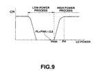
- the compensation temperature of the fifth magnetic layer is adjusted in the vicinity of the Curie temperature of the writing layer. Then the temperature at the centre of the laser irradiated part becomes higher than the compensation temperature of the fifth magnetic layer during the recording period, and the magnetization of the laser irradiated part and its peripheral region which oppose each other, generate a leaky magnetic field from the peripheral region and a leaky magnetic field from the laser irradiated part which reinforce each other.
- the saturation magnetization of the fifth magnetic layer at room temperature can not have a large value.
- the greater the composition of rare earth is than the compensation composition the higher the compensation temperature is above room temperature, and at the same time the larger the saturation magnetization at room temperature is. If the saturation magnetization becomes larger than a certain value, the compensation temperature exceeds the Curie temperature, and the compensation temperature is ineffective. Therefore, in this medium a large leaky magnetic field is not generated from the peripheral region and the laser irradiated part as can be seen in Figure 2.
- EP-A-0440486 discloses a recording medium designed for use as a light modulation overwriting medium and including a recording layer, a non-magnetic layer, a bias layer and a reversal preventive layer for preventing reversal of the bias layer.
- the medium is designed such that the leakage magnetic field from the bias layer varies dependent on the temperature and is effective to cause information to be recorded on the recording layer.
- An object of this invention is to provide a magnetooptical recording medium capable of being overwritten which does not involve a deterioration of quality of reproduction signal and recording sensitivity and which either reduces the necessary strength of the external recording bias magnetic field or does not need it, also therefore it is possible to make the recording and/or reproducing apparatus smaller, simpler and cheaper.
- a magnetooptical recording medium capable of being overwritten by light modulation as defined in claim 1.
- FIG. 3 shows a cross sectional view of a magnetooptical recording medium structure in accordance with an embodiment of this invention.
- a stack of magnetic laminated films 3 is formed over a transparent substrate 1, which comprises for example polycarbonate or glass, with a dielectric layer 2a interposed between the substrate 1 and stack 3, and finally a dielectric layer 2b formed as a protective layer over the stack 3.
- Figure 4 is a cross sectional view of the stack 3 of magnetic laminated films of Figure 3.
- the first magnetic 21 layer is a memory layer 21 capable of storing information bits.
- the second magnetic layer 22 is a writing layer in which information bits can be written during a recording period by application of laser radiation effective to heat the medium to a chosen temperature level.
- the third magnetic layer 23 is a switching layer which turns switches on or off the exchange coupling between the second magnetic layer 22 and the fourth magnetic layer 24.
- the fourth magnetic layer is an initializing layer having a magnetization which is arranged in a direction for initializing the second magnetic layer 22.
- the fifth magnetic layer is a bias layer for applying a bias magnetic field to the second magnetic layer 22 during the recording period when the medium is heated to the chosen temperature level.
- the layers 21-25 of the stack 3 are laminated in turn.
- the fifth layer 25 and the fourth layer 24 be laminated to contact each other, although the fifth layer 25 and the fourth layer 24 can be laminated in reverse order to that shown in Figure 4 as shown in Figure 5.
- the first magnetic layer 21 satisfies the following conditions at room temperature.
- the first magnetic layer 21 satisfies the following condition near the Curie temperature T 1 of the first magnetic layer 21: 2 Ms 1 Hc 1 h 1 ⁇ ⁇ w 12
- the second magnetic layer 22 satisfies the following conditions lower than the Curie temperature T 3 of the third magnetic layer: 2 MS 2 Hc 2 h 2 ⁇ ⁇ w 24 - ⁇ w 12 where:
- the fourth magnetic layer 24 satisfies the following conditions at the temperature between the Curie temperature T 2 of the second magnetic layer 22 and room temperature: 2 Ms 4 Hc 4 h 4 > ⁇ w 24 where:
- the fifth magnetic layer 25 satisfies the following condition near the Curie temperature T 4 of the fifth magnetic layer 25: 2 Ms 5 Hc 5 h 5 ⁇ ⁇ w 45 where:
- an intermediate layer for controlling the interface domain wall energy or other adjusting layer etc can be formed. But, as the fifth layer 25 and the fourth layer 24 need to be laminated to contact each other, it is not desirable to form such intermediate layers between the fifth and fourth layers.
- the Curie temperatures of the first magnetic layer 21 to the fourth layer 24 of the stack of magnetic laminated films are defined as T 1 to T 4 respectively, the relationship: room temperature ⁇ T 3 ⁇ T 1 ⁇ T 2 ⁇ T 4 is required.
- the Curie temperature T 5 of the fifth magnetic layer 25 is needed to be substantially equal to or less than T 2 .
- the Curie temperature T 5 is preferably in the range from T 2 - 90° to T 2 + 5°, more preferably from T 2 - 40° to T 2 °C, more preferably from T 2 - 20° to T 2 °C.
- the level of the saturation magnetization of the fifth magnetic layer 25 needs to be larger than that of the second magnetic layer 22.
- the level of the saturation magnetization is preferably not less than .35 Am -1 /cc (350 emu/cc) at the room temperature, more preferably not less than .45 Am -1 /cc (450 emu/cc), and even more preferably not less than .6 Am -1 /cc (600 emu/cc) .
- the layers of magnetooptical recording medium are formed for example by continuous sputtering using a magnetron sputtering apparatus or continuous evaporation.
- each magnetic layer which constitutes the stack of magnetic laminated layers 3 is preferably continuously formed without breaking into the vacuum to make the layers exchange couple to each other.
- dielectric layer 2a transparent dielectric materials such as for example Si 3 N 4 , AlN, SiO 2 , ZnS, MgF 2 may be used.
- Each magnetic layer within the stack 3 of the magnetic laminated layers preferably comprises a rare earth-transition metal magnetic film.
- the rare earth-transition metal magnetic film for example rare earth-iron group amorphous metal alloy composed of 5 to 50 at% (atomic %) of one or more kinds of rare earth metal elements, i.e. Pr, Nd, Sm, Gd, Tb, Dy, Ho and so on, and 95 to 50 at% of one or more kinds of iron group metal elements may be used.
- a small quantity of Cr, Mn, Cu, Ti, Al, Si, Pt, In and so on can be added.
- the saturation magnetization of each magnetic layer within the stack 3 can be controlled by controlling the composition ratio of the rare earth and transition metal elements.
- the coercive force of each magnetic layer in the stack of magnetic laminated films 3 can be controlled by the saturation magnetization, but primarily it can be controlled by adjustment of the vertical magnetic anisotropy.
- the vertical magnetic anisotropy can be controlled by selecting the elements within each magnetic layer. Generally, the materials of the TbDy group and so on have large vertical magnetic anisotropy and large coercive force. But the materials of the Gd group have small vertical magnetic anisotropy and small coercive force. A nonmagnetic element can be added to reduce the vertical magnetic anisotropy.
- the Curie temperature of each magnetic layer within the stack 3 can also be controlled by controlling the composition ratio of rare earth and transition metal elements.
- substitution of Co for Fe as the transition metal element is preferable.
- substitution of Co for 1 at % of Fe produces an almost 6°C rise of the Curie temperature. Using this relation it is possible to obtain an adequate Curie temperature by adjusting the quantity of Co added.
- the Curie temperature it is also possible to reduce the Curie temperature by adding a small amount of nonmagnetic element such as Cr, Ti and so on. Also it is possible to adjust the Curie temperature by adjusting the composition of two or more kinds of rare earth element.
- a nonmagnetic or magnetic intermediate layer may be inserted in some interfaces between the layers of the stack 3. Magnetic intermediate layers having relatively small vertical magnetic anisotropy are superior in respect of manufacturing stability and so on.
- the thickness of each layer can be controlled by adjusting the deposition time.
- a magnetooptical recording medium in accordance with this invention is not restricted to above mentioned structure.
- a magnetic layer which has a high Curie temperature on the first magnetic layer 21 (memory layer) as a reproduction layer.
- a layer which has another function and to make a plurality of layers constitute each layer. It is possible to protect both side of the magnetic layer with a dielectric layer, and to add a metal layer directly on or with an interposed thermal buffer layer in order to adjust the thermal functioning of the medium.
- a magnetooptical recording medium in accordance with this invention may include all such variations.
- a leaky magnetic field can be effectively generated without opposing the floating magnetic field from the peripheral region of the irradiated portion of the medium, because that there is no remaining magnetism in the laser irradiated part of the fifth magnetic layer 25 during the high temperature level recording as the Curie temperature T 5 of the bias layer 25 is exceeded.
- the fifth magnetic layer 25 is exchange coupled with the fourth magnetic layer, i.e. the initializing layer 24, which has a Curie temperature T 4 which is higher than that of the second magnetic layer 22, there is no formation of domains in the fifth layer 25 by laser irradiation during the recording period.
- the fourth magnetic layer i.e. the initializing layer 24, which has a Curie temperature T 4 which is higher than that of the second magnetic layer 22, there is no formation of domains in the fifth layer 25 by laser irradiation during the recording period.
- optical magnetic recording and/or reproducing apparatus for use with the above embodiment of a medium in accordance with this invention, adaptations of known magnetooptical recording and/or reproducing apparatus can be used with an appropriate laser driving circuit for selecting the two different laser powers effective to heat the medium to TL and TH respectively.
- the recording bias magnetic field generating means in prior art apparatus may be omitted if the magnetooptical recording medium of this invention may be made capable of recording without bias magnetic field.
- the recording bias magnetic field generating means cannot be omitted.
- FIG. 7 A suitable magnetooptical recording and/or reproducing apparatus for use with a medium in accordance with an embodiment of the present invention is shown schematically in Figure 7.
- 120 denotes a magnetooptical recording medium in accordance with an embodiment of this invention.
- 121 denotes a spindle motor which rotates the medium 120.
- 122 is an optical head on which an optical system including components such as a photo sensor 122a, a laser source 122b, polarisers (not shown) and so on are mounted.
- 123 is a laser driving circuit which drives said laser source to emit radiation at a required power.
- 124 is a modulation circuit which modulates recording data using a desired modulation method and outputs modulated recording data to the laser driving circuit.
- 125 is a reproducing circuit which produces reproduced data from the output of the photo sensor 122a.
- the recording data modulated by the modulating circuit is output to the laser driving circuit 123.
- the laser driving circuit 123 drives the laser source 122b to produce laser radiation intensity modulated to one of the two above mentioned powers PH and PL which are effective to heat the irradiated part of the medium to one of the two recording temperatures TH and TL.
- the laser power is modulated to PH.
- the laser power is modulated to PL.
- the magnetic state of the irradiated part of the medium passes through state C and becomes state D.
- state D the magnetization of the first magnetic layer 21, the third magnetic layer 23 and the fifth magnetic layer 25 disappears because the temperature of the irradiated portion of the medium exceeds the Curie temperature T 1 , T 3 of the first and third layers 21, 23 and slightly exceeds the Curie temperature T 5 of the fifth magnetic layer 25.
- the magnetization of the second magnetic layer 22 is easily reversed by the leaky magnetic field of the fifth magnetic layer 25 in the area of the magnetic recording medium peripheral to the irradiated part of the medium (i.e. peripheral to the recording domain), because the exchange coupling of the second magnetic layer 22 with other the layers is cut off.
- the irradiated part of the medium cools down, and when the temperature becomes lower than the Curie temperature T 1 of the first magnetic layer 21, the magnetization of the first layer 21 reappears, this reappearing magnetization followed by the exchange coupling in the direction parallel to the direction of the magnetization of the second magnetic layer 22.
- the magnetization of the third magnetic layer 23 is oriented in the direction parallel to the direction of the magnetization of the fourth magnetic layer 24 by the influence of the exchange coupling from the fourth magnetic layer 24 which has a large coercive force.
- the magnetization of the second magnetic layer 22 under the influence of the exchange coupling from the fourth magnetic layer 24 with the interposed third magnetic layer 23 is oriented in the direction parallel to the direction of the magnetization of the fourth magnetic layer 24.
- this coercive force prevents the magnetization of the first magnetic layer 21 from orienting to the direction parallel to the direction of the magnetization of the second magnetic layer 22 due to the influence of the exchange coupling from the second magnetic layer 22.
- the magnetization state B is obtained in which the magnetization state of the memory layer 21 is opposite to that of the other layers 22, 23, 24, 25 in the stack 3.
- the magnetic state of the irradiated part of the medium becomes state C.
- the magnetization of the third magnetic layer 23 disappears, because the temperature reaches the Curie temperature T 3 of the third magnetic layer 23 of the irradiated portion of the medium.
- the magnetization of the first magnetic layer 21 becomes oriented in a direction parallel to the direction of the magnetization of the second magnetic layer 22 by the influence of the exchange coupling from the second magnetic layer 22 as the coercive force of the first magnetic layer 21 decreases. After the end of the laser irradiation at power PL, the laser irradiated part of the medium cools, and finally state A is obtained.
- the required two valued recording is executed by forming either state A or state B on the medium according to the recording data by application of either high power (PH) or low power (PL) laser pulses.
- PH high power
- PL low power
- An irradiating laser of sufficiently low power so as not to erase data on the medium is directed onto the medium and the reflected light from the medium detected with the photo sensor 122a via appropriate polarisers (not shown).
- the amount of received light on the photo sensor 122a changes according to the direction of the magnetization at the irradiated portion of the medium due to the change in polarization produced by the magnetic Kerr effect. Based on these changes in received light intensity, recorded data is reproduced by the reproducing circuit 125.
- Dy, Tb, Fe, Co, Al and B doped Si targets were installed in a DC magnetron sputtering apparatus (not shown).
- a polycarbonate disc substrate was fixed on a substrate holder, then the chamber of the apparatus was exhausted to a high vacuum level of 1x10 -5 Pa or less using a cryopump.
- Ar gas was introduced into the exhausted chamber to obtain 0.3 Pa vacuum level in the chamber.
- the substrate was rotated.
- a 80 nm layer of SiN was deposited.
- Each magnetic layer 21 to 25 was formed by applying DC power to each Dy, Tb, Fe, Co target, the composition of each magnetic layer being controlled by adjustment of the DC power.
- the first magnetic layer 21 was retained in the vacuum chamber for 30 minutes and then the second magnetic layer 22 was formed. After the second magnetic layer, each of the remaining magnetic layers were formed in turn.
- the exchange coupling force at the interface between the first magnetic layer 21 and the second magnetic layer 22 and interface wall energy was reduced and controlled to almost 1 erg/cm' .
- a 20nm layer of TbFeCo as the first magnetic layer 21, a 20nm layer of DyFeCo as the second magnetic layer 22, a 5nm layer of TbFe as the third magnetic layer, a 20 nm layer of TbCo as the fourth magnetic layer 24, a 20nm layer of TbFeCo as the fifth magnetic layer 25 were deposited.
- a 50 nm layer of Al was deposited.
- the composition of the fifth layer was adjusted to obtain a value of saturation magnetization of almost .6 Am -1 /cc (600 emu/cc) at room temperature.
- the relative composition of rare earth and iron group element in each magnetic layer, except the fifth layer 25, was adjusted in order to obtain a composition such that the saturation magnetization at room temperature for each layer 21-24 was in the order of 0 Am -1 /cc (0 emu/cc), i.e. in the vicinity of compensation composition.
- the amount of Co in the first magnetic layer 21, the second magnetic layer 22 and the fifth magnetic layer 25, was adjusted to obtain Curie temperatures of respectively 145°C, 250°C and 240°C.
- the Curie temperature of the third magnetic layer was 125°C and the Curie temperature of the fourth magnetic layer was higher than 300°C.
- N 2 gas was introduced in the chamber in addition to the Ar gas, and the SiN layer was formed using a reactive sputtering method.
- the magnetooptical recording medium obtained by the above mentioned process was set on a drive apparatus having a optical head including a laser of wavelength 780nm, and an object lens of NA0.55. Rotating the medium with a fixed cycle of 60Hz, a measurement was performed at the 24mm radial position. Before the measurement, the whole periphery of the disc was erased by high output laser irradiation, and the fourth magnetic layer 24, i.e. the initializing layer was magnetized in a direction normal to the layers 21 to 25.
- the power level of the irradiating laser at which the recording of 1 MHz signals at a 50% duty cycle may be produced was detected with an applied recording bias magnetic field of 23.88 KAm -1 (300 Oe).
- the power PH th was found to be 5.0 mW.
- the power PH was found to be 8.5 mW.
- the pulse power PH was arranged to be 8.5 mW
- the pulse power PL was arranged to be 4.0 mW
- 2.2 MHz signals were initially recorded. 5.8 MHz signals were then overwritten over the 2.2 MHz signals by changing the recording bias magnetic field.
- the dependency of the CN ratio on the recording bias magnetic field is shown in Fig. 10.
- a comparative magnetooptical recording medium was prepared in the same way as the Example 1, except that the fifth magnetic layer was not formed.
- the result of the C/N measurement on the recording medium, which was performed in the same way as for Example 1 is shown in Figures 10 and 11.
- Example 1 and Comparative Example 1 good characteristics were obtained without observation of the initially recorded signal spectrum.
- a recording bias magnetic field of 12.7 KAm -1 (160 Oe) was needed in order to obtain CN ratio of 47dB which is needed for digital recording.
- the fifth magnetic layer 25 functioned as a bias layer, a leaky magnetic field which corresponded to 11.14 KAm -1 (140 Oe) was generated in the recording time and the necessary external recording bias magnetic field was reduced.
- the second, third and fourth Comparative Examples of magnetooptical recording media were formed in the same way as the Example 1, except that the fifth magnetic layer was not formed and that the composition of the second magnetic layer 22 was shifted to the iron group element rich side, and the saturation magnetization of the second magnetic layer at room temperature was adjusted to .15 Am -1 /cc (150 emu/cc) in Comparative Example 2, .25 Am -1 /cc (250 emu/cc) in Comparative Example 3, and .35 Am -1 /cc (350 emu/cc) in Comparative Example 4 in order to increase the demagnetizing field of the writing layer 22.
- the result of the measurements on the recording media, which were performed the same way on the Example 1, are shown in Figure 11.
- the Comparative Example 5 of a magnetooptical recording medium was formed in the same way as Example 1, except for not forming the fifth magnetic layer, and that the composition of the fourth magnetic layer 24 was shifted to the iron group element rich side, the saturation magnetization of the fourth magnetic layer 24 at room temperature was adjusted to .2 Am -1 /cc (200 emu/cc), the thickness of the fourth magnetic layer 24 was 80 nm, and the initializing layer 24 also acted as a bias layer.
- the recording sensitivity of the magnetooptical recording medium was measured in the same way as Example 1.
- PH th was found to be 6.8 mV, using a value of PL of 5.5 mW (which was 0.8 times PH th ), the pulse power PH at which the CN ratio was saturated was found to be 12.3mW using a 5.8MHz recording signal.
- the optical magnetic recording medium was prepared in the same way as Example 1, except that between the first magnetic layer 21 and the second magnetic layer 27, a magnetic layer composed of Gd group material was inserted as an adjusting layer to control the interface wall energy between the layers.
- the fifth magnetic layer 25 which functions as a bias layer was arranged between the third magnetic layer 23 and fourth magnetic layer 24.
- the magnetic laminated films were arranged as shown in Table 1.
- the saturation magnetization of the optical magnetic recording medium given in Table 1 means the value at room temperature.
- a symbol “ -” means that the iron group element sub lattice magnetization is dominant at room temperature
- the symbol " +” means that the rare earth element sub lattice magnetization is dominant at room temperature.
- the composition ratio (x) of Tb was adjusted in the range of from 9 to 17 at%, whilst the ratio (y) of Co was adjusted in the range of from 5 to 16 at%.
- the Curie temperature (T 5 ) of the fifth magnetic layer 25 was fixed at 220°C, the saturation magnetization (M 5 ) was changed in the range of from .2 to .6 Am -1 /cc (-200 to - 700 emu/cc).
- the CN ratio dependent character on a recording bias magnetic field of each magnetooptical recording medium was measured in the same way as Example 1, and the minimum recording magnetic field Hb min required to obtain a CN ratio of 47 dB was measured.
- the Curie temperature T 5 of the fifth magnetic layer 25 is too low compared to that of the second magnetic layer 22, the peak position along the plane of the film face of the leaky magnetic field strength will shift to outside of the position at which a recording domain was formed by irradiation of the laser beam. If T 5 is too high compared to that of the second magnetic layer 22, the peak position in the plane of the film face of the stack 3 of leaky magnetic field strength will shift to the inside of the position of the recording domain. It is thought that if the Curie temperature (T 5 ) of the fifth magnetic layer 25 is too high compared to that of the second magnetic layer 22, there will be a remaining magnetization at the position of the recording domain of the fifth magnetic layer 25, and there will be no generation of an effective leaky magnetic field. Therefore the necessary external recording bias magnetic field will increase immediately.
- the reason that the center of adequate temperature range may be located at a lower temperature than the Curie temperature (T 2 ) of the second magnetic layer 22, is thought to be because the relationship of the above mentioned peak position in the plane of the film face of the leaky magnetic field strength, and the position at which a domain was formed, and the temperature incline in the direction of the film thickness.
- a magnetooptical recording medium was prepared in the same way as Example 2, except for not forming the fifth magnetic layer.
- the measurement on the recording medium was performed the same way as for Example 2.
- the minimum recording bias magnetic field (Hbmin) was measured to be 13.52 KAm -1 (170 Oe).
- the third example of a magnetooptical recording medium in accordance with the invention was prepared in the same way as for Example 1, except that the magnetic laminated films had the composition and thicknesses shown in Table 2.
- the dependency of the CN ratio on the recording bias magnetic field of this magnetooptical recording medium was measured in the same way as for Example 1, and the result is shown in Fig. 14.
- a CN ratio of 52 dB was obtained with no external bias recording field and in a large magnetic field range from -7.96 to 35.8 KAm -1 (-100 to +450 Oe) a CN ratio not less than 47 dB was obtained.
- the ambient temperature is quoted as room temperature. However, in some recording and/or reproducing apparatus the ambient temperature may be more or less than room temperature.
Applications Claiming Priority (6)
| Application Number | Priority Date | Filing Date | Title |
|---|---|---|---|
| JP26303995 | 1995-10-11 | ||
| JP263039/95 | 1995-10-11 | ||
| JP26303995 | 1995-10-11 | ||
| JP26869396 | 1996-10-09 | ||
| JP268693/96 | 1996-10-09 | ||
| JP8268693A JPH09167388A (ja) | 1995-10-11 | 1996-10-09 | 光磁気記録媒体、該媒体を用いた情報記録再生装置及び情報記録再生方法 |
Publications (3)
| Publication Number | Publication Date |
|---|---|
| EP0768656A2 EP0768656A2 (en) | 1997-04-16 |
| EP0768656A3 EP0768656A3 (en) | 1998-05-20 |
| EP0768656B1 true EP0768656B1 (en) | 2004-01-14 |
Family
ID=26545832
Family Applications (1)
| Application Number | Title | Priority Date | Filing Date |
|---|---|---|---|
| EP96307371A Expired - Lifetime EP0768656B1 (en) | 1995-10-11 | 1996-10-10 | Magnetooptical recording medium and recording method and apparatus using the medium |
Country Status (4)
| Country | Link |
|---|---|
| US (1) | US5949743A (enExample) |
| EP (1) | EP0768656B1 (enExample) |
| JP (1) | JPH09167388A (enExample) |
| DE (1) | DE69631317T2 (enExample) |
Families Citing this family (4)
| Publication number | Priority date | Publication date | Assignee | Title |
|---|---|---|---|---|
| JPH10275369A (ja) | 1997-01-31 | 1998-10-13 | Canon Inc | 情報記録媒体の製造方法および該方法による情報記録媒体 |
| US7145847B2 (en) * | 2002-08-28 | 2006-12-05 | Canon Kabushiki Kaisha | Annealed optical information recording medium and optical information recording/reproducing apparatus for the same |
| JP2005025889A (ja) * | 2003-07-04 | 2005-01-27 | Canon Inc | 光学的記録媒体への情報記録方法 |
| JP2005174518A (ja) * | 2003-12-15 | 2005-06-30 | Canon Inc | 磁性記録媒体及びその製造方法 |
Family Cites Families (23)
| Publication number | Priority date | Publication date | Assignee | Title |
|---|---|---|---|---|
| US5239524A (en) * | 1985-06-11 | 1993-08-24 | Nikon Corporation | Over write capable magnetooptical recording method, and magnetooptical recording apparatus and medium used therefor |
| US5367507A (en) * | 1985-06-11 | 1994-11-22 | Nikon Corporation | Over write capable magnetooptical recording method, and magnetooptical recording apparatus and medium used therefor |
| US5475657A (en) * | 1985-06-11 | 1995-12-12 | Nikon Corporation | Overwrite capable magnetooptial recording apparatus |
| US5440531A (en) * | 1985-06-11 | 1995-08-08 | Nikon Corporation | Magneto-optical reproducing method |
| JP2521908B2 (ja) * | 1985-06-11 | 1996-08-07 | 株式会社ニコン | オ―バ―ライト可能な光磁気記録方法、それに使用される光磁気記録装置及び光磁気記録媒体、並びに変調方法、変調装置及び光磁気記録媒体 |
| JPS63153752A (ja) * | 1986-07-08 | 1988-06-27 | Canon Inc | 光磁気記録媒体及びその記録方法 |
| EP0838814B1 (en) * | 1986-07-08 | 2002-02-27 | Canon Kabushiki Kaisha | Magnetooptical recording medium allowing overwriting with two or more magnetic layers and recording method utilizing the same |
| JPS6352354A (ja) * | 1986-08-20 | 1988-03-05 | Sony Corp | 熱磁気記録方法 |
| CA1322408C (en) * | 1986-08-20 | 1993-09-21 | Tomiji Tanaka | Thermomagnetic recording method applying power modulated laser on a magnetically coupled double layer structure of perpendicular anisotropy film |
| AU600576B2 (en) * | 1987-04-24 | 1990-08-16 | Sony Corporation | Thermomagnetic recording method applying power modulated laser on a magnetically coupled multi-layer structure of perpendicular anisotropy magnetic film |
| JP2762435B2 (ja) * | 1987-04-24 | 1998-06-04 | ソニー株式会社 | 熱磁気記録方法 |
| JP2630976B2 (ja) * | 1988-03-19 | 1997-07-16 | 富士通株式会社 | 光磁気記録媒体 |
| WO1990002400A1 (fr) * | 1988-08-24 | 1990-03-08 | Mitsubishi Denki Kabushiki Kaisha | Support d'enregistrement magneto-optique et procede de production de ce support |
| US5163031A (en) * | 1988-12-07 | 1992-11-10 | Canon Kabushiki Kaisha | Method of recording tetra-value signal on magneto-optical recording medium with plural magnetic layers |
| US5087532A (en) * | 1989-08-01 | 1992-02-11 | Minnesota Mining And Manufacturing Company | Direct-overwrite magneto-optic media |
| US5512366A (en) * | 1989-11-14 | 1996-04-30 | Mitsubishi Denki Kabushiki Kaisha | Magneto-optic recording medium and apparatus |
| JP2503708B2 (ja) * | 1989-11-14 | 1996-06-05 | 三菱電機株式会社 | 光磁気記録媒体及び装置 |
| JP2707769B2 (ja) * | 1989-11-14 | 1998-02-04 | 三菱電機株式会社 | 光磁気記録媒体及びそれを用いた光磁気記録再生装置 |
| JP3015475B2 (ja) * | 1990-01-31 | 2000-03-06 | 株式会社東芝 | 光磁気記録方法及びそれに使用される光磁気記録媒体 |
| JPH04134741A (ja) * | 1990-09-27 | 1992-05-08 | Nikon Corp | 4層膜構造のオーバーライト可能な光磁気記録媒体 |
| US5418076A (en) * | 1990-11-20 | 1995-05-23 | Canon Kabushiki Kaisha | Magnetic-optical recording medium |
| JPH04192138A (ja) * | 1990-11-26 | 1992-07-10 | Mitsubishi Electric Corp | 光磁気記録媒体 |
| EP0487847A1 (en) * | 1990-11-26 | 1992-06-03 | Mitsubishi Denki Kabushiki Kaisha | Magnetooptical recording medium |
-
1996
- 1996-10-09 JP JP8268693A patent/JPH09167388A/ja active Pending
- 1996-10-10 US US08/728,849 patent/US5949743A/en not_active Expired - Fee Related
- 1996-10-10 EP EP96307371A patent/EP0768656B1/en not_active Expired - Lifetime
- 1996-10-10 DE DE1996631317 patent/DE69631317T2/de not_active Expired - Fee Related
Also Published As
| Publication number | Publication date |
|---|---|
| EP0768656A2 (en) | 1997-04-16 |
| JPH09167388A (ja) | 1997-06-24 |
| US5949743A (en) | 1999-09-07 |
| DE69631317T2 (de) | 2004-11-18 |
| DE69631317D1 (de) | 2004-02-19 |
| EP0768656A3 (en) | 1998-05-20 |
Similar Documents
| Publication | Publication Date | Title |
|---|---|---|
| EP1143434A2 (en) | A magnetooptical recording medium and information recording and reproducing methods using the recording medium | |
| EP0899727B1 (en) | Signal-reproducing method utilizing magnetic domain wall displacement and apparatus therefor | |
| US6117544A (en) | Magneto-optical recording medium | |
| US6150038A (en) | Magneto-optical recording medium | |
| US6430115B1 (en) | Magneto-optical recording device with three distinct layers | |
| US5493545A (en) | Magnetooptical recording medium with overwrite capabilities and method for using the same | |
| US6853606B2 (en) | Magneto-optical storage medium capable of transferring magnetic domain from recording layer to reproducing layer | |
| US5412627A (en) | A magneto-optical recording system including a recording medium having a reversal preventive layer for preventing a magnetization reversal of a bias layer which is magnetostatically coupled to a recording layer | |
| EP0768656B1 (en) | Magnetooptical recording medium and recording method and apparatus using the medium | |
| KR940001452B1 (ko) | 광자기 기록매체 및 이를 사용한 광자기 기록재생장치 | |
| JPH10134435A (ja) | 光磁気記録媒体 | |
| US5965285A (en) | Magneto-optical recording medium and reproducing method for the same | |
| US5462811A (en) | Magneto-optical recording media and mangeto-optical device using the media | |
| US5325345A (en) | Magneto-optical method and apparatus for recording/reproducing data | |
| US5814418A (en) | Magneto-optical recording medium and method for reading out information from the same | |
| US5587974A (en) | Magneto-optical recording medium having two magnetic layers with perpendicular magnetic anisotropy, and information recording method having the same | |
| US6033538A (en) | Magneto-optical recording medium production method | |
| US5434844A (en) | Magneto-optical recording media and magneto-optical recording device using the same | |
| US5876807A (en) | Magneto-optical recording medium production method | |
| US6811889B2 (en) | Magneto-optical recording medium having a GDFECO readout magnetic film | |
| US5719831A (en) | Magneto-optical recording medium cartridge which employs magnets | |
| JP2815034B2 (ja) | 光磁気記録媒体の製造方法 | |
| JP3592399B2 (ja) | 光磁気記録媒体 | |
| JPH0589536A (ja) | 光磁気記録媒体 | |
| JP2000173116A (ja) | 光磁気記録媒体及び再生装置 |
Legal Events
| Date | Code | Title | Description |
|---|---|---|---|
| PUAI | Public reference made under article 153(3) epc to a published international application that has entered the european phase |
Free format text: ORIGINAL CODE: 0009012 |
|
| AK | Designated contracting states |
Kind code of ref document: A2 Designated state(s): DE FR GB IT NL |
|
| PUAL | Search report despatched |
Free format text: ORIGINAL CODE: 0009013 |
|
| AK | Designated contracting states |
Kind code of ref document: A3 Designated state(s): DE FR GB IT NL |
|
| 17P | Request for examination filed |
Effective date: 19980930 |
|
| 17Q | First examination report despatched |
Effective date: 20010126 |
|
| GRAH | Despatch of communication of intention to grant a patent |
Free format text: ORIGINAL CODE: EPIDOS IGRA |
|
| GRAS | Grant fee paid |
Free format text: ORIGINAL CODE: EPIDOSNIGR3 |
|
| GRAA | (expected) grant |
Free format text: ORIGINAL CODE: 0009210 |
|
| AK | Designated contracting states |
Kind code of ref document: B1 Designated state(s): DE FR GB IT NL |
|
| PG25 | Lapsed in a contracting state [announced via postgrant information from national office to epo] |
Ref country code: NL Free format text: LAPSE BECAUSE OF FAILURE TO SUBMIT A TRANSLATION OF THE DESCRIPTION OR TO PAY THE FEE WITHIN THE PRESCRIBED TIME-LIMIT Effective date: 20040114 Ref country code: IT Free format text: LAPSE BECAUSE OF FAILURE TO SUBMIT A TRANSLATION OF THE DESCRIPTION OR TO PAY THE FEE WITHIN THE PRESCRIBED TIME-LIMIT;WARNING: LAPSES OF ITALIAN PATENTS WITH EFFECTIVE DATE BEFORE 2007 MAY HAVE OCCURRED AT ANY TIME BEFORE 2007. THE CORRECT EFFECTIVE DATE MAY BE DIFFERENT FROM THE ONE RECORDED. Effective date: 20040114 |
|
| REG | Reference to a national code |
Ref country code: GB Ref legal event code: FG4D |
|
| REF | Corresponds to: |
Ref document number: 69631317 Country of ref document: DE Date of ref document: 20040219 Kind code of ref document: P |
|
| NLV1 | Nl: lapsed or annulled due to failure to fulfill the requirements of art. 29p and 29m of the patents act | ||
| ET | Fr: translation filed | ||
| PLBE | No opposition filed within time limit |
Free format text: ORIGINAL CODE: 0009261 |
|
| STAA | Information on the status of an ep patent application or granted ep patent |
Free format text: STATUS: NO OPPOSITION FILED WITHIN TIME LIMIT |
|
| 26N | No opposition filed |
Effective date: 20041015 |
|
| PGFP | Annual fee paid to national office [announced via postgrant information from national office to epo] |
Ref country code: GB Payment date: 20061018 Year of fee payment: 11 |
|
| PGFP | Annual fee paid to national office [announced via postgrant information from national office to epo] |
Ref country code: DE Payment date: 20061220 Year of fee payment: 11 |
|
| GBPC | Gb: european patent ceased through non-payment of renewal fee |
Effective date: 20071010 |
|
| PG25 | Lapsed in a contracting state [announced via postgrant information from national office to epo] |
Ref country code: DE Free format text: LAPSE BECAUSE OF NON-PAYMENT OF DUE FEES Effective date: 20080501 |
|
| REG | Reference to a national code |
Ref country code: FR Ref legal event code: ST Effective date: 20080630 |
|
| PGFP | Annual fee paid to national office [announced via postgrant information from national office to epo] |
Ref country code: FR Payment date: 20061019 Year of fee payment: 11 |
|
| PG25 | Lapsed in a contracting state [announced via postgrant information from national office to epo] |
Ref country code: GB Free format text: LAPSE BECAUSE OF NON-PAYMENT OF DUE FEES Effective date: 20071010 |
|
| PG25 | Lapsed in a contracting state [announced via postgrant information from national office to epo] |
Ref country code: FR Free format text: LAPSE BECAUSE OF NON-PAYMENT OF DUE FEES Effective date: 20071031 |