EP0767455A2 - Méthode et appareil pour le jugement d'un milieu d'enregistrement optique, et méthode et appareil de commande d'asservissement de focalisation - Google Patents
Méthode et appareil pour le jugement d'un milieu d'enregistrement optique, et méthode et appareil de commande d'asservissement de focalisation Download PDFInfo
- Publication number
- EP0767455A2 EP0767455A2 EP96115978A EP96115978A EP0767455A2 EP 0767455 A2 EP0767455 A2 EP 0767455A2 EP 96115978 A EP96115978 A EP 96115978A EP 96115978 A EP96115978 A EP 96115978A EP 0767455 A2 EP0767455 A2 EP 0767455A2
- Authority
- EP
- European Patent Office
- Prior art keywords
- optical record
- record medium
- optical
- information
- focus error
- Prior art date
- Legal status (The legal status is an assumption and is not a legal conclusion. Google has not performed a legal analysis and makes no representation as to the accuracy of the status listed.)
- Withdrawn
Links
Images


Classifications
-
- G—PHYSICS
- G11—INFORMATION STORAGE
- G11B—INFORMATION STORAGE BASED ON RELATIVE MOVEMENT BETWEEN RECORD CARRIER AND TRANSDUCER
- G11B7/00—Recording or reproducing by optical means, e.g. recording using a thermal beam of optical radiation by modifying optical properties or the physical structure, reproducing using an optical beam at lower power by sensing optical properties; Record carriers therefor
- G11B7/12—Heads, e.g. forming of the optical beam spot or modulation of the optical beam
- G11B7/135—Means for guiding the beam from the source to the record carrier or from the record carrier to the detector
- G11B7/1372—Lenses
-
- G—PHYSICS
- G11—INFORMATION STORAGE
- G11B—INFORMATION STORAGE BASED ON RELATIVE MOVEMENT BETWEEN RECORD CARRIER AND TRANSDUCER
- G11B19/00—Driving, starting, stopping record carriers not specifically of filamentary or web form, or of supports therefor; Control thereof; Control of operating function ; Driving both disc and head
- G11B19/02—Control of operating function, e.g. switching from recording to reproducing
- G11B19/12—Control of operating function, e.g. switching from recording to reproducing by sensing distinguishing features of or on records, e.g. diameter end mark
-
- G—PHYSICS
- G11—INFORMATION STORAGE
- G11B—INFORMATION STORAGE BASED ON RELATIVE MOVEMENT BETWEEN RECORD CARRIER AND TRANSDUCER
- G11B7/00—Recording or reproducing by optical means, e.g. recording using a thermal beam of optical radiation by modifying optical properties or the physical structure, reproducing using an optical beam at lower power by sensing optical properties; Record carriers therefor
- G11B7/002—Recording, reproducing or erasing systems characterised by the shape or form of the carrier
- G11B7/0037—Recording, reproducing or erasing systems characterised by the shape or form of the carrier with discs
-
- G—PHYSICS
- G11—INFORMATION STORAGE
- G11B—INFORMATION STORAGE BASED ON RELATIVE MOVEMENT BETWEEN RECORD CARRIER AND TRANSDUCER
- G11B7/00—Recording or reproducing by optical means, e.g. recording using a thermal beam of optical radiation by modifying optical properties or the physical structure, reproducing using an optical beam at lower power by sensing optical properties; Record carriers therefor
- G11B7/08—Disposition or mounting of heads or light sources relatively to record carriers
- G11B7/09—Disposition or mounting of heads or light sources relatively to record carriers with provision for moving the light beam or focus plane for the purpose of maintaining alignment of the light beam relative to the record carrier during transducing operation, e.g. to compensate for surface irregularities of the latter or for track following
- G11B7/0945—Methods for initialising servos, start-up sequences
-
- G—PHYSICS
- G11—INFORMATION STORAGE
- G11B—INFORMATION STORAGE BASED ON RELATIVE MOVEMENT BETWEEN RECORD CARRIER AND TRANSDUCER
- G11B7/00—Recording or reproducing by optical means, e.g. recording using a thermal beam of optical radiation by modifying optical properties or the physical structure, reproducing using an optical beam at lower power by sensing optical properties; Record carriers therefor
- G11B2007/0003—Recording, reproducing or erasing systems characterised by the structure or type of the carrier
- G11B2007/0006—Recording, reproducing or erasing systems characterised by the structure or type of the carrier adapted for scanning different types of carrier, e.g. CD & DVD
-
- G—PHYSICS
- G11—INFORMATION STORAGE
- G11B—INFORMATION STORAGE BASED ON RELATIVE MOVEMENT BETWEEN RECORD CARRIER AND TRANSDUCER
- G11B7/00—Recording or reproducing by optical means, e.g. recording using a thermal beam of optical radiation by modifying optical properties or the physical structure, reproducing using an optical beam at lower power by sensing optical properties; Record carriers therefor
- G11B2007/0003—Recording, reproducing or erasing systems characterised by the structure or type of the carrier
- G11B2007/0009—Recording, reproducing or erasing systems characterised by the structure or type of the carrier for carriers having data stored in three dimensions, e.g. volume storage
- G11B2007/0013—Recording, reproducing or erasing systems characterised by the structure or type of the carrier for carriers having data stored in three dimensions, e.g. volume storage for carriers having multiple discrete layers
Definitions
- the present invention is related with a reproducing apparatus in a case of reproducing, by using one reproducing apparatus, information from a plurality of types of optical record mediums, such as optical disks of various types and the like, to which the information is recorded by a phase pit and the like or a magnetic way, and more particularly, it is related with a judging method and apparatus for judging the type of the optical record medium to be reproduced.
- a focus servo controlling method and apparatus for carrying out a focus servo control in order to beam-condense (focus) the light beam which has an optimal size at a reproducing position of the optical record medium.
- CD/LD compatible reproducing apparatus which can reproduce a CD (Compact Disk) and a LD (Laser Disk) with one reproducing unit.
- a distance from a record medium surface to an information record surface namely, a thickness of a protecting layer
- the LD e.g. 1.2 mm in common.
- a focus servo control is needed for carrying out an optimal focus servo control corresponding to the type of the optical disk to be reproduced.
- a focus search action for setting a standard position when carrying out the appropriate focus servo control. This focus search action moves an optical pickup in a direction perpendicular to the optical disk by a predetermined length to thereby detect an optimal focus position on the basis of a focus error signal (S-shaped signal) outputted at that time.
- the optical disk mounted in the reproducing apparatus in a case of judging whether the optical disk mounted in the reproducing apparatus is the CD or the LD, it is judged whether or not the focus servo is locked by moving the optical disk into an area located outside the CD and inside the LD and rotating the optical disk by utilizing a diameter difference between the CD and the LD. Namely, if it is locked, the optical disk is judged as the LD. If it is not locked, the optical disk is judged as the CD.
- a DVD Digital Video Disk
- a CD/DVD compatible reproducing apparatus is being developed which can reproduce both the DVD and the CD.
- the thickness of the protecting layer of the DVD is set to a thickness (0.6 mm) approximately half of that of the protecting layer of the CD.
- one method may be considered in which an aberration correcting element is inserted into an optical path of the light beam, depending on the type of the optical disk to be reproduced.
- this method will require a mechanical device which puts and retracts the aberration correcting element into and from the optical path on the basis of the type of the optical disk to be reproduced.
- this method is not suited for miniaturization of the optical pickup.
- a bifocal lens is developed through which it is possible to irradiate two light beams focused on different positions on one straight line. This bifocal lens is explained with reference to FIGS.6A and 6B.
- the bifocal lens comprises a diffraction grating H and an objective lens R arranged on one optical path.
- a light beam L made into a parallel light by a collimator lens C is divided into three beams of a 0 order light, a +1 order light and a -1 order light by the diffraction grating H.
- the 0 order light and the +1 order light are made focused on different positions on one straight line.
- this bifocal lens is adapted such that the +1 order light is focused on a position further from the objective lens R than the 0 order light, and that the 0 order light is optimally beam-condensed on the information record surface of the DVD (e.g. 0.6 mm from the disk surface), and also as shown in FIG.6B, the +1 order light is optimally beam-condensed on the information record surface of the CD (e.g. 1.2 mm from the disk surface).
- the DVD is superior in linear velocity of record information to the CD.
- the focus servo gain and a focus servo frequency band in the focus search action are different between the CD and the DVD.
- the focus servo frequency band more actually, it is necessary that the DVD is widely set on a higher frequency side than the CD.
- the above object of the present invention can be achieved by an optical record medium judging method of judging types of optical record mediums, which distances from external surfaces thereof to information record surfaces thereof recorded with record information are different from each other.
- the optical record medium judging method is provided with the steps of: irradiating an information record surface of an optical record medium to be reproduced with a plurality of light beams to be focused on different positions on one optical axis; moving, so as to change a relative distance parallel to said one optical axis between an objective lens for prescribing focal points of the plurality of light beams respectively and the information record surface, the objective lens; receiving a plurality of reflection lights of the plurality of light beams reflected from the information record surface respectively, associated with a change of the relative distance; generating a plurality of focus error signals on the basis of the plurality of received reflection lights respectively; and judging a type of the optical record medium by comparing levels of the generated focus error signals respectively with a predetermined standard level.
- the information record surface of the optical record medium is irradiated with a plurality of light beams to be focused on different positions on one optical axis. Then, the objective lens is moved, so that the relative distance parallel to the optical axis between the objective lens and the information record surface is changed. Then, a plurality of reflection lights of the plurality of light beams reflected from the information record surface respectively are received in association with the change of the relative distance. Then, a plurality of focus error signals are generated on the basis of the plurality of received reflection lights respectively. Finally, the type of the optical record medium is judged by comparing levels of the generated focus error signals respectively with a predetermined standard level.
- the types of the optical record mediums can be judged according to the optical record medium judging method of the present invention.
- the optical record mediums include first and second optical record mediums which distances from the external surfaces thereof to the information record surfaces thereof are different from each other.
- the irradiating step is provided with the steps of irradiating the information record surface with a first light beam to reproduce the record information from the first optical record medium, and irradiating the information record surface with a second light beam to reproduce the record information from the second optical record medium, the second light beam having a focal point farther from the objective lens than the first light beam.
- the receiving step is provided with the steps of receiving a first reflection light of the first light beam reflected from the information record surface, and receiving a second reflection light of the second light beam reflected from the information record surface.
- the focus error signal generating step is provided with the steps of generating a first focus error signal on the basis of the received first reflection light, and generating a second focus error signal on the basis of the received second reflection light.
- the judging step is provided with the steps of judging the type of the optical record medium as the first optical record medium if at least one of the levels of the first and second focus error signals is equal to or higher than the predetermined standard level, and judging the type as the second optical record medium if both of the levels are lower than the predetermined standard level.
- the information record surface is irradiated with the first light beam to reproduce the record information from the first optical record medium
- the information record surface is irradiated with the second light beam to reproduce the record information from the second optical record medium.
- the second light beam has a focal point farther from the objective lens than the first light beam. Then, the first reflection light of the first light beam reflected from the information record surface is received, and the second reflection light of the second light beam reflected from the information record surface is received. Then, the first focus error signal is generated on the basis of the received first reflection light, and the second focus error signal is generated on the basis of the received second reflection light.
- the type of the optical record medium is judged as the first optical record medium if at least one of the levels of the first and second focus error signals is equal to or higher than the predetermined standard level, and the type is judged as the second optical record medium if both of the levels are lower than the predetermined standard level.
- the first and second optical record mediums even if the diameters of the first and second optical record mediums are same to each other as in the case of the CD and the DVD. Namely, as long as the distances between the external surfaces to the information record surfaces are different between the first and second optical record mediums, the types of the optical record mediums can be judged according to this aspect of the present invention.
- the first light beam may be a 0 order light generated by a bifocal lens
- the second light beam may be a +1 order light generated by the bifocal lens
- the above object of the present invention can be also achieved by a focus servo controlling method of judging types of optical record mediums, on which record informations are recorded at linear velocities different from each other, and setting a focus servo gain and a focus servo frequency band corresponding to each of the types of the optical record mediums.
- the focus servo controlling method is provided the steps of: irradiating an information record surface recorded with record information of an optical record medium to be reproduced with a plurality of light beams to be focused on different positions on one optical axis; moving, so as to change a relative distance parallel to said one optical axis between an objective lens for prescribing focal points of the plurality of light beams respectively and the information record surface, the objective lens on the basis of a control signal; receiving a plurality of reflection lights of the plurality of light beams reflected from the information record surface respectively, associated with a change of the relative distance; generating a plurality of focus error signals on the basis of the plurality of received reflection lights respectively; judging a type of the optical record medium by comparing peak values of the generated focus error signals respectively with a predetermined standard level; setting the focus servo gain and the focus servo frequency band on the basis of the peak values; and generating the control signal, wherein the focus servo gain and the focus servo frequency band are set in the setting step by repeat
- the information record surface is irradiated with a plurality of light beams to be focused on different positions on one optical axis.
- the objective lens is moved on the basis of the control signal generated by the control signal generating step, so that the relative distance parallel to the optical axis between the objective lens and the information record surface is changed.
- a plurality of reflection lights of the plurality of light beams reflected from the information record surface respectively are received in association with the change of the relative distance.
- a plurality of focus error signals are generated on the basis of the plurality of received reflection lights respectively.
- the type of the optical record medium is judged by comparing peak values of the generated focus error signals respectively with a predetermined standard level.
- the focus servo gain and the focus servo frequency band are set on the basis of the peak values.
- the focus servo gain and the focus servo frequency band are set in the setting step by repeating following operations with respect to the linear velocities of the optical record mediums one after another. That is to say, firstly, the control signal to move the objective lens at the moving speed corresponding to the fastest linear velocity is generated. Then, if the judged type of the optical record medium is one recorded with the record information at the fastest linear velocity, the focus servo gain and the focus servo frequency band are set on the basis of the peak value of the focus error signal generated while the objective lens is moved at the moving speed corresponding to the fastest linear velocity.
- the control signal to move the objective lens at the moving speed corresponding to the second fastest linear velocity is generated.
- the focus servo gain and the focus servo frequency band are set on the basis of the peak value of the focus error signal generated while the objective lens is moved at the moving speed corresponding to the second fastest linear velocity. Then, until the optical record medium is appropriately judged and the focus servo gain and the focus servo frequency band are appropriately set, these operations are repeated.
- the setting operations of the focus servo gain and the focus servo frequency band can be performed efficiently within a relatively short time period. Further, the judging operation of the optical record medium and the betting operations of the focus servo gain and the focus servo frequency band can be performed in one consecutive procedure. Therefore, it is possible to speedily perform the rising operation of the compatible reproducing apparatus, which can reproduce the optical record mediums of different types even if the diameters thereof are same to each other as in the case of the CD and the DVD. Namely, as long as the linear velocities of recording the information are different from each other, the rising operation can be speedily performed according to the focus servo controlling method of the present invention.
- the optical record mediums include a first optical record medium, on which the record information is recorded at a first linear velocity, and a second optical record medium, on which the record information is recorded at a second linear velocity lower than the first linear velocity and which distance from the external surface thereof to the information record surface thereof is different from that of the first optical record medium.
- the moving step is provided with the step of firstly moving the objective lens at a first moving speed corresponding to the first linear velocity.
- the receiving step is provided with the step of firstly receiving the plurality of reflection lights associated with the change of the relative distance in the firstly moving step.
- the focus error generating step is provided with the step of firstly generating the plurality of focus error signals on the basis of the reflection lights received by the firstly receiving step.
- the method is further provided with the step of firstly calculating the peak values of the focus error signals respectively generated by the firstly generating step.
- the judging step is provided with the steps of judging the optical record medium as the first optical record medium if at least one of the peak values calculated by the firstly calculating step is equal to or higher than the predetermined standard level, and judging the optical record medium as the second optical record medium if all of the peak values calculated by the firstly calculating step are lower than the predetermined standard level.
- the setting step is provided with the step of firstly setting the focus servo gain and the focus servo frequency band on the basis of a highest peak value of the peak values calculated by the firstly calculating step, if the optical record medium is judged as the first optical record medium.
- the moving step is further provided with the step of secondly moving the objective lens at a second moving speed, which corresponds to the second linear velocity and which is lower than the first moving speed, if the optical record medium is judged as the second optical record medium.
- the receiving step is further provided with the step of secondly receiving the plurality of reflection lights associated with the change of the relative distance in the secondly moving step.
- the focus error generating step is further provided with the step of secondly generating the plurality of focus error signals on the basis of the reflection lights received by the secondly receiving step.
- the focus error controlling method is further provided with the step of secondly calculating the peak values of the focus error signals respectively generated by the secondly generating step.
- the setting step is provided with the step of secondly setting the focus servo gain and the focus servo frequency band on the basis of a highest peak value of the peak values calculated by the secondly calculating step.
- the objective lens is firstly moved at the first moving speed corresponding to the first linear velocity. Then, the plurality of reflection lights associated with the change of the relative distance in the firstly moving step are firstly received. Then, the plurality of focus error signals are firstly generated on the basis of the reflection lights received by the firstly receiving step. Then, the peak values of the focus error signals respectively generated by the firstly generating step are firstly calculated. Then, the optical record medium is judged as the first optical record medium if at least one of the peak values calculated by the firstly calculating step is equal to or higher than the predetermined standard level.
- the optical record medium is judged as the second optical record medium if all of the peak values calculated by the firstly calculating step are lower than the predetermined standard level. Then, the focus servo gain and the focus servo frequency band are firstly set on the basis of the highest peak value of the peak values calculated by the firstly calculating step, if the optical record medium is judged as the first optical record medium. After that, if the optical record medium is judged as the second optical record medium, the objective lens is secondly moved at the second moving speed.
- the second moving speed corresponds to the second linear velocity and is lower than the first moving speed. Then, the plurality of reflection lights associated with the change of the relative distance in the secondly moving step are secondly received.
- the plurality of focus error signals are secondly generated on the basis of the reflection lights received by the secondly receiving step.
- the peak values of the focus error signals respectively generated by the secondly generating step are secondly calculated.
- the focus servo gain and the focus servo frequency band are secondly set on the basis of the highest peak value of the peak values calculated by the secondly calculating step.
- the setting operations of the focus servo gain and the focus servo frequency band can be performed efficiently within a relatively short time period. Further, the judging operation of the optical record medium and the setting operations of the focus servo gain and the focus servo frequency band can be performed in one consecutive procedure. Therefore, it is possible to speedily perform the rising operation of the compatible reproducing apparatus, which can reproduce the first and second optical record mediums even if the diameters of the first and second optical record medium are same to each other as in the case of the CD and the DVD. Namely, as long as the distances between the external surfaces to the information record surfaces are different between the first and second optical record medium, the rising operation can be speedily performed according to this aspect of the present invention.
- the first light beam may be a 0 order light generated by a bifocal lens
- the second light beam may be a +1 order light generated by the bifocal lens
- the above object of the present invention can be also achieved by an optical record medium judging apparatus for judging types of optical record mediums, which distances from external surfaces thereof to information record surfaces thereof recorded with record information are different from each other.
- the optical record medium judging apparatus is provided with: a light irradiating device for irradiating an information record surface of an optical record medium to be reproduced with a plurality of light beams to be focused on different positions on one optical axis; a lens moving device for moving, so as to change a relative distance parallel to said one optical axis between an objective lens for prescribing focal points of the plurality of light beams respectively and the information record surface, the objective lens; a light receiving device for receiving a plurality of reflection lights of the plurality of light beams reflected from the information record surface respectively, associated with a change of the relative distance; a focus error generating device for generating a plurality of focus error signals on the basis of the plurality of received reflection lights respectively; and a judging device for judging a type of the optical
- the optical record mediums include first and second optical record mediums which distances from the external surfaces thereof to the information record surfaces thereof are different from each other.
- the light irradiating device is provided with a device for irradiating the information record surface with a first light beam to reproduce the record information from the first optical record medium, and irradiating the information record surface with a second light beam to reproduce the record information from the second optical record medium, the second light beam having a focal point farther from the objective lens than the first light beam.
- the light receiving device is provided with a first receiving device for receiving a first reflection light of the first light beam reflected from the information record surface, and a second receiving device for receiving a second reflection light of the second light beam reflected from the information record surface.
- the focus error signal generating device is provided with a first generating device for generating a first focus error signal on the basis of the received first reflection light, and a second generating device for generating a second focus error signal on the basis of the received second reflection light.
- the type judging device is provided with a first judging device for judging the type of the optical record medium as the first optical record medium if at least one of the levels of the first and second focus error signals is equal to or higher than the predetermined standard level, and a second judging device for judging the type as the second optical record medium if both of the levels are lower than the predetermined standard level.
- the first light beam may be a 0 order light generated by a bifocal lens
- the second light beam may be a +1 order light generated by the bifocal lens
- the aforementioned optical record medium judging method of the present invention can be certainly performed, and the same advantageous effects as those of the optical record medium judging method can be achieved by the optical record medium judging apparatus according to the present invention.
- the above object of the present invention can be also achieved by a focus servo controlling apparatus for judging types of optical record mediums, on which record informations are recorded at linear velocities different from each other, and setting a focus servo gain and a focus servo frequency band corresponding to each of the types of the optical record mediums.
- the focus servo controlling apparatus is provided with: a light irradiating device for irradiating an information record surface recorded with record information of an optical record medium to be reproduced with a plurality of light beams to be focused on different positions on one optical axis; a lens moving device for moving, so as to change a relative distance parallel to said one optical axis between an objective lens for prescribing focal points of the plurality of light beams respectively and the information record surface, the objective lens on the basis of a control signal; a light receiving device for receiving a plurality of reflection lights of the plurality of light beams reflected from the information record surface respectively, associated with a change of the relative distance; a focus error generating device for generating a plurality of focus error signals on the basis of the plurality of received reflection lights respectively; a type judging device for judging a type of the optical record medium by comparing peak values of the generated focus error signals respectively with a predetermined standard level; a servo setting device for setting the focus servo gain and the focus
- the optical record mediums include a first optical record medium, on which the record information is recorded at a first linear velocity, and a second optical record medium, on which the record information is recorded at a second linear velocity lower than the first linear velocity and which distance from the external surface thereof to the information record surface thereof is different from that of the first optical record medium.
- the lens moving device is provided with a first moving device for firstly moving the objective lens at a first moving speed corresponding to the first linear velocity.
- the light receiving device is provided with a first receiving device for firstly receiving the plurality of reflection lights associated with the change of the relative distance of the objective lens moved by the first moving device.
- the focus error generating device is provided with a first generating device for firstly generating the plurality of focus error signals on the basis of the reflection lights received by the first receiving device.
- the apparatus is further provided with a first calculating device for firstly calculating the peak values of the focus error signals respectively generated by the first generating device.
- the type judging device is provided with a first judging device for judging the optical record medium as the first optical record medium if at least one of the peak values calculated by the first calculating device is equal to or higher than the predetermined standard level, and a second judging device for judging the optical record medium as the second optical record medium if all of the peak values calculated by the first calculating device are lower than the predetermined standard level.
- the servo setting device is provided with a first setting device for firstly setting the focus servo gain and the focus servo frequency band on the basis of a highest peak value of the peak values calculated by the first calculating device, if the optical record medium is judged as the first optical record medium.
- the lens moving device is further provided with a second moving device for secondly moving the objective lens at a second moving speed, which corresponds to the second linear velocity and which is lower than the first moving speed, if the optical record medium is judged as the second optical record medium.
- the light receiving device is further provided with a second receiving device for secondly receiving the plurality of reflection lights associated with the change of the relative distance of the objective lens moved by the second moving device.
- the focus error generating device is further provided with a second generating device for secondly generating the plurality of focus error signals on the basis of the reflection lights received by the second receiving device.
- the focus servo controlling apparatus is further provided with a second calculating device for secondly calculating the peak values of the focus error signals respectively generated by the second generating device; and the servo setting device is provided with a second setting device for secondly setting the focus servo gain and the focus servo frequency band on the basis of a highest peak value of the peak values calculated by the second calculating device.
- the first light beam may be a 0 order light generated by a bifocal lens
- the second light beam may be a +1 order light generated by the bifocal lens
- the aforementioned focus servo controlling method of the present invention can be certainly performed, and the same advantageous effects as those of the focus servo controlling method can be achieved by the focus servo controlling apparatus according to the present invention.
- optical record medium judging method and apparatus of the present invention it is possible to judge the CD and the DVD in the CD/DVD compatible reproducing apparatus having the bifocal lens. Further, according to the above described focus servo controlling method and apparatus of the present invention, it is possible to rapidly set the focus servo gain and the focus servo frequency band in parallel to the above mentioned judging action. Consequently, it is possible to-carry out the rapid rising operation in the CD/DVD compatible reproducing apparatus.
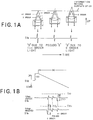
- the two light beams L from an optical pickup having a bifocal lens are set such that the +1 order light is optimally beam-condensed on the CD and the 0 order light is optimally beam-condensed on the DVD, and the +1 order light is longer in focal length than the 0 order light.
- the bifocal lens is moved up for the CD, at first the +1 order light is beam-condensed on an information record surface of the CD and then a focus error signal Sfe is detected. Next, a pseudo signal of the focus error signal Sfe induced by a fact that a reflection light from the optical disk of the +1 order light is passed through an optical path of the 0 order light is detected.
- a focus error signal Sfe corresponding to the 0 order light is detected.
- an optical system is set such that the 0 order light is optimally beam-condensed for the DVD and the +1 order light is optimally beam-condensed for the CD.
- the optimal beam-condensing condition is not kept, for example, because of generation of spherical aberration. Therefore, in a case that the optical disk is the CD, the focus error signal Sfe corresponding to the +1 order light has the highest level, and the focus error signal Sfe corresponding to the 0 order light has the lowest level. In contrast with this, in a case that the optical disk is the DVD, the focus error signal Sfe corresponding to the 0 order light has the highest level, and the focus error signal Sfe corresponding to the +1 order light has the lowest level.
- the level (a symbol FE2 of FIG.1B) of the focus error signal Sfe corresponding to the 0 order light in the case that the optical disk is the DVD is higher than the level (a symbol FE1 of FIG.1B) of the focus error signal Sfe corresponding to the +1 order light in the case that the optical disk is the CD as shown in FIG. 1B.
- a predetermined threshold TH1 is defined as a value between the level of the focus error signal Sfe corresponding to the 0 order light in the case that the optical disk is the DVD and the level of the focus error signal Sfe corresponding to the +1 order light in the case that the optical disk is the CD. Then, if one of the levels of the detected focus error signals Sfe is higher than the threshold TH1, the optical disk to which at that time the light beam L is irradiated can be judged as the DVD. If all the levels are lower than the threshold TH1, the optical disk to which at that time the light beam L is irradiated can be judged as the CD.
- the optical disk is the DVD
- a level of a first focus error signal Sfe focus error signal Sfe corresponding to the 0 order light
- the threshold TH1 it is higher than the threshold TH1 in this case. Therefore, when the level of one of the focus error signals Sfe detected in the moving down process of the bifocal lens exceeds the threshold TH1, the optical disk is judged as the DVD.
- the levels of all the focus error signals Sfe do not exceed the threshold TH1, the optical disk is judged as the CD.
- FIG.2 is a schematic block diagram of a DVD/CD compatible reproducing apparatus in accordance with the present invention.
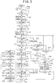
- FIG.3 is the flow chart showing the operation of the DVD/CD compatible reproducing apparatus shown in FIG.2.
- FIGS.4 and 5 are the timing charts showing the operations of the DVD/CD compatible reproducing apparatus shown in FIG.2.
- the timing chart in FIG.4 shows the operation in a case that the CD is mounted in the DVD/CD compatible reproducing apparatus.
- the timing chart in FIG.5 shows the operation in a case that the DVD is mounted.
- a DVD/CD compatible reproducing apparatus S 1 shown in FIG.2 in an optical disk 1 that is the CD, information is recorded on an information track TR by a phase pit or a magnetic record mark.
- a light spot Sp is formed by the light beam L from a laser diode (not shown ) included in an optical pickup P.
- FIG.2 as an optical system installed within the optical pickup P, only devices related especially with the present invention are described, and general devices, such as a mirror, a deflecting plate and the like, are omitted.
- a light-receiving device 2 is included within the optical pickup P, and is a four-divided photo detector. This light-receiving device 2 receives a reflection light which is reflected from the light spot Sp and to which astigmatism is given by a cylindrical lens ER, and outputs a detection signal.
- a subtracter 3 mutually subtracts signals, in which two detectors opposite to each other in the light-receiving device 2 are synthesized respectively, and outputs the focus error signal Sfe.
- a LPF (Low Pass Filter) 4 removes an unnecessary frequency component equal to or more than a sampling frequency of an A/D converter 6 described later from the focus error signal Sfe, and converts into a wave form that can be used as the focus error signal Sfe.
- a VCA (Voltage Controlled Amplifier) circuit 5 sets a focus servo gain on the basis of a control signal Sc1 described later.
- the A/D converter 6 converts the focus error signal Sfe amplified on the basis of the set focus servo gain into a digital signal.
- a digital equalizer circuit 7 is composed of a digital filter and the like, and sets, on the basis of a control signal Sc2 described later, a focus servo frequency band corresponding to the focus error signal Sfe converted into the digital signal.
- a PWM (Pulse Width Modulation) circuit 8 generates, on the basis of a control signal Sc3 described later, generates a focus drive signal Sfd having a pulse width corresponding to a level of the inputted focus error signal Sfe. At this time, on the basis of the control signal Sc3, the focus drive signal Sfd is generated so as to drive a bifocal lens 11 as an objective lens as described later at the moving speed for an operation described later.
- a driver circuit 9 amplifies the focus drive signal Sfd and outputs it to an actuator 10 described later.
- the actuator 10 is composed of an electromagnet coil and the like, and drives the bifocal lens 11 into an optical axis direction (focus direction) of the light beam L, on the basis of the focus drive signal Sfd.
- An adder 12 adds all the detection signals outputted from the light-receiving device 2 to thereby generate a read RF (Radio Frequency) signal.
- This read RF signal is outputted to an demodulator (not shown) and the like as a reproduction signal including record information, and also outputted to an RF envelope circuit 13.
- the RF envelope circuit 13 is composed of a low pass filter and the like, and outputs an amplitude amount (envelope) of the read RF signal, from which a high frequency signal due to a pit is removed among the RF signal.
- the LPF 14 extracts only a low band frequency component from the envelope.
- An A/D converter 15 converts the envelope into a digital signal and outputs it to a servo controller 16.
- the servo controller 16 calculates, on the basis of the focus error signal Sfe, a peak value thereof, and also, on the basis of the maximum peak value of the peak values, outputs the control signal Sc1 to set the focus servo gain, the control signal Sc2 to set the focus servo frequency band and the control signal Sc3 to control the moving speed of the bifocal lens 11.
- the servo controller 16 controls the whole focus servo action in the DVD/CD compatible reproducing apparatus S 1 .
- Information required for these operations of the servo controller 16 is transiently stored in a RAM (Random Access Memory) 17.
- the rising operations shown in FIGS.3 to 5 are mainly carried out under the control of the servo controller 16.
- the bifocal lens 11 is, for example, driven to reciprocate twice (respective two times in moving up and moving down actions) in the optical axis direction of the light beam L.
- the disk is judged by a method shown in FIGS.1A and 1B, on the basis of the peak value of the focus error signal Sfe detected at that time. If it is judged as the DVD, the focus servo gain and the focus servo frequency band are set by using the maximum value of the detected peak value.
- the bifocal lens 11 is, for example, further driven to reciprocate twice (respective two times in the moving up and moving-gown actions) in the optical axis direction of the light beam L.
- the focus servo gain and the focus servo frequency band are set on the basis of the maximum peak value of the focus error signals Sfe detected at that time.
- a "+" side of the focus drive signal Sfd corresponds to the moving up action (a direction approaching the optical disk 1) of the bifocal lens 11
- a "-" side corresponds to the moving down action (a direction going away from the optical disk 1) of the bifocal lens 11.
- "UH” is a focus drive signal Sfd corresponding to an upper limit position of the bifocal lens 11.
- UL is a focus drive signal Sfd corresponding to a lower limit position of the bifocal lens 11.
- Step S1 a register and the like included in the servo controller 16 are initialized (Step S1), in the rising operations in the DVD/CD compatible reproducing apparatus S 1 in which the CD is mounted.
- a reference numeral M denotes the number of the moving up and moving down movements of the bifocal lens 11.
- Step 1 When the initialization (Step 1) is ended, whether or not the optical disk 1 is mounted in the reproducing apparatus S 1 is detected by a detecting device (not shown in FIG.2) (Step S2). In a case that it is not mounted (Step S2 ; NO), the operation is waited as it is. In a case that the optical disk 1 is mounted (Step S2 ; YES), the optical disk 1 is rotated by a spindle motor (not shown in FIG.2) (Step S3).
- Step S3 When the optical disk is started to be rotated (Step S3), the focus drive signal Sfd is outputted, on the basis of the control signal Sc3, so as to move down the bifocal lens 11 in a short time (Step S4, and refer to a symbol (A) of FIG. 4). Then, it is judged whether or not the bifocal lens 11 moves down to a lower limit position (Step S5). Namely, it is checked whether or not
- Step S5 When the bifocal lens 11 is moved down to a lower limit position (Step S5; YES), the operation, is waited for a time period T1 corresponding to a preparing period (for example, a necessary period until a movement of the lens becomes stable) to detect the focus error signal Sfe (Step S6). After that, it is set such that the bifocal lens 11 is moved up at the first moving speed corresponding to the linear velocity of the DVD (Step S7). Next, it is judged whether the value of M is "0" or an even value (Step S8).
- a preparing period for example, a necessary period until a movement of the lens becomes stable
- Step S8 Since the value of M is "0" at this state (Step S8 ; YES), the focus drive signal Sfd is outputted in order to start to move up the bifocal lens 11 located at the lower limit position at the first moving speed (Step S9, and refer to a symbol (B) of FIG.4). Then, it is judged whether or not any one of the peak values exceeds the threshold TH1 (refer to a symbol TH1 of FIG.1), for a focus error signal Sfe0 (refer to FIG.4) detected at the moving up process (Step S11).
- Step S11 the peak value of the focus error signal Sfe0 does not exceed the threshold TH1 as explained in FIG.1 (Step S11 ; NO).
- Step S21 the value of M is "0" or the even value
- Step S21 the value of M is "0" presently (Step S21 ; YES)
- Step S22 it is judged whether or not the bifocal lens 11 is located at an upper limit position (Step S22). Namely, it is checked whether or not
- Step S22 In a case of the upper limit position (Step S22 ; YES), M is increased (incremented) by "1" and set to “1” in this case (Step S23). It is judged whether or not the value of M is equal to or more than "4" (Step S40). Since it is not "4" presently (Step S40 ; NO), the operation is returned to the step S8.
- Step S8 Since the value of M is "1" at the step S8 (Step S8 ; NO), at this time the focus drive signal Sfd is outputted in order to move down the bifocal lens 11 (Step S10, and refer to a symbol (C) of FIG. 4). It is judged whether or not the peak value exceeds the threshold TH1 (refer to the symbol TH1 of FIG.1), for a focus error signal Sfe1 (refer to FIG.4) detected at the moving down process (Step S11). Since the optical disk 1 is presently assumed to be the CD, the peak value of the focus error signal Sfe1 does not exceed the threshold TH1 similarly to the above mentioned case (Step S11 ; NO).
- Step S21 it is judged whether the value of M is "0" or the even value. Since the value of M is "1" presently (Step S21 ; NO), it is judged whether or not the bifocal lens 11 is located at the lower limit position (Step S24). In a case that it is not located at the lower limit position (Step S24 ; NO), the operation is returned to the step S8 in order to continue the moving down action as it is. In a case of the lower limit position (Step S24 ; YES), M is increased by "1" and set to "2" in this case (Step S23). It is judged whether or not the value of M is equal to or more than "4" (Step S40). Since it is not "4" presently (Step S40 ; NO), the operation is returned to the step S8.
- Step S10 When the value of M becomes "3" and the bifocal lens 11 is moved down (Step S10), then the value of M is increased by "1" at the step S23 through the steps S11, S21 and S22, and set to "4" in this case. The judgment result becomes "YES” at the step S40.
- the optical disk 1 Since the peak value of the focus error signals Sfe detected until that time does not exceed the threshold TH1 (refer to FIG.4), the optical disk 1 is judged as the CD (Step S41). It is set such so as to carry out a later moving action of the bifocal lens 11 at the second moving speed corresponding to the linear velocity of the record information recorded in the CD (slower than that of the DVD) (Step S42).
- Step S43 It is judged whether or not the value of M is equal to or more than "5" (Step S43). Since it is "4" presently (Step S43 ; NO), the operation is returned to the step S8. Since the value of M is "4" (Step S8 ; YES), the focus drive signal Sfd is outputted in order to move up the bifocal lens 11 located at the lower limit position at the second moving speed (Step S9, and refer to a symbol (D) of FIG.4). A focus error signal Sfe4 detected at this moving up process does not exceed the threshold TH1, since the optical disk 1 is the CD (Step S11 ; NO). It is judged whether the value of M is "0" or the even value (Step S21).
- Step S23 Since it is "4" presently (Step S23; YES), it is judged whether or not the bifocal lens 11 is located at the upper limit position (Step S22). In a case that it is not the upper limit position (Step S22 ; NO), the operation is returned to the step S8 so as to continue the moving up action as it is. In a case of the upper limit position (Step S22 ; YES), M is increased by 1 and set to "5" in this case (Step S23). It is judged whether or not the value of M is equal to or more than "4" (Step S40).
- Step S40 Since the value of M is "5" presently (Step S40 ; YES), it is judged whether or not the value of M is equal to or more than "5" through the steps S41 and S42 (Step S43). Since it is "5" presently (Step S43 ; YES), the value of M is decreased (decremented) by "1" and set to "4" in this case (Step S44). Then, the peak value of the focus error signals Sfe4 is calculated in the servo controller 16 on the basis of the focus error signal Sfe4 (Step S13). Then, the peak value at the previous time is compared with the peak value at the current time (Step S14).
- Step S14 In a case that the previous value is larger (Step S14 ; NO), the operation is shifted to the step S16. In a case that the current value is larger (Step S14 ; YES), the current value is stored (Step S15), and the operation is shifted to the step S16. It is judged whether or not the value of M is equal to or more than "4" (Step S16). Since it is "4" presently (Step S16 ; YES), the operation is waited for a waiting time period T3 corresponding to the case of the CD so as to shift to a process after the peak value is calculated (Step S18). The value of M is increased by "1" and set to "5" in this case (Step S19).
- Step S20 It is judged whether or not the value of M is equal to or more than "8" (Step S20). Since it is "5" presently (Step S20 ; NO), the operation is returned to the step S8. It is judged whether or not the value of M is "0" or the even value (Step S8).
- Step S8 Since the value of M is "5" presently at the step S8 (Step S8 ; NO), the operation is shifted to the step S10 in order to move down the bifocal lens 11. Then, the bifocal lens 11 is moved down (Step S10). Similarly, the operations at the step S11 and the steps S21 to S24, and the steps S40 to S44, and the steps S13 to S16, and the step S18 are carried out. The value of M is increased by "1" and set to "6" in this case (Step S19). The judgment result becomes "NO" at the step S20, and becomes "YES” at the step S8. Then, the operation is shifted to the step S9 in order to move up the bifocal lens 11.
- Step S20 When the value of M becomes "8" (Step S20 ; YES), the bifocal lens 11 is once moved down to the lower limit position (Steps S26 and S27).
- a focus servo gain Gf is set (Step S28) by using the maximum value of the peak values stored (Step S15) until that time.
- Step S29 and S30 After that, again the bifocal lens 11 is moved up to the upper limit position (Steps S29 and S30).
- the focus servo loop is closed (Step S31) by using a focus error signal Sfe8 detected at that time (refer to FIG.4).
- a tracking servo gain Gt is set (Step S32) by reading the peak value of the tracking error signal obtained on the basis of a three-beam method, a DPP (Differential Push-Pull) method and the like (Step S32), and then the reproduction of the record information is started (Step S33).
- the rising operation in a case that the optical disk 1 is the CD is ended as mentioned above.
- the timing chart of FIG.4 shows the wave form of the focus error signal Sfe and focus drive signal Sfd at this time.
- any one of focus error signals Sfe9 to Sfe12 detected while the value of M is ranging from "0" to "3" exceeds the threshold TH1, as shown in FIG.5 (Step S11 ; YES).
- the operation is waited for a waiting period T2 corresponding to the case of the DVD for shifting to a process after the peak value is calculated. While the value of M is ranging from "0" to "3", the bifocal lens 11 is reciprocated two times in upward and downward directions at the first moving speed, as shown in FIG.5.
- the value of M is "3"
- the value of M is set to "4" at the step S19.
- the operation is returned to the step S9 through the processing of the steps S20 and S8, and then the focus drive signal Sfd (refer to a symbol (E) of FIG.5) is outputted in order to move up the bifocal lens 11.
- the moving speed in this case is still the first moving speed.
- the optical disk 1 is judged as the DVD (Step S25). After that, the operations similar to the case in which the optical disk 1 is the CD (the steps S26 to S33) are carried out.
- the rising operation in a case that the optical disk is the DVD is ended as mentioned above.
- the timing chart of FIG.5 shows the wave form of the focus error signal Sfe and the focus drive signal Sfd at this time. As can be seen from FIGS.4 and 5, in a case that the optical disk 1 is the DVD, the rising operation thereof is ended in a shorter time than that of the CD.
- the type of the optical disk 1 is judged on the basis of the focus error signal Sfe obtained at a time of moving the bifocal lens 11 at the first moving speed.
- the focus servo gain and the focus servo frequency band are set on the basis of the peak value as it is.
- the optical disk 1 is judged as the CD
- the bifocal lens 11 is continuously moved at the second moving speed.
- the focus servo gain and the focus servo frequency band are set on the basis of the focus error signals Sfe4 to Sfe8 obtained in conjunction with the above mentioned movement.
- the threshold TH1 of judging the optical disk is set as a single value.
- a threshold for the DVD and a threshold for the CD which is lower than that of the DVD, it is possible to surely judge the CD and also possible to use the operational steps in common to the DVD and the CD.
- By setting a plurality of thresholds it is easy for one skilled in the art to modify in such a way that the present invention is applied to judging of more than two kinds of the optical disks.
- the optical disk After the optical disk is judged, it is allowable to change the moving upper limit UH and the moving lower limit UL of the lens.
- the example in which the focus error signal is read every four times is explained, it is not limited to this example. It is allowable to carry out at least one reading action or more. Furthermore, it is allowable to make the number of reading action different for each disk type as the occasion demands.
Applications Claiming Priority (2)
| Application Number | Priority Date | Filing Date | Title |
|---|---|---|---|
| JP260569/95 | 1995-10-06 | ||
| JP7260569A JPH09106617A (ja) | 1995-10-06 | 1995-10-06 | 情報記録媒体判別方法及び装置並びにフォーカスサーボ制御方法及び装置 |
Publications (2)
| Publication Number | Publication Date |
|---|---|
| EP0767455A2 true EP0767455A2 (fr) | 1997-04-09 |
| EP0767455A3 EP0767455A3 (fr) | 1997-07-02 |
Family
ID=17349777
Family Applications (1)
| Application Number | Title | Priority Date | Filing Date |
|---|---|---|---|
| EP96115978A Withdrawn EP0767455A3 (fr) | 1995-10-06 | 1996-10-04 | Méthode et appareil pour le jugement d'un milieu d'enregistrement optique, et méthode et appareil de commande d'asservissement de focalisation |
Country Status (3)
| Country | Link |
|---|---|
| US (2) | US5790493A (fr) |
| EP (1) | EP0767455A3 (fr) |
| JP (1) | JPH09106617A (fr) |
Cited By (6)
| Publication number | Priority date | Publication date | Assignee | Title |
|---|---|---|---|---|
| WO1997034296A2 (fr) * | 1996-03-12 | 1997-09-18 | Deutsche Thomson-Brandt Gmbh | Appareil d'ecriture et/ou de lecture de supports d'enregistrement optique de differentes conceptions |
| EP0810588A2 (fr) * | 1996-05-28 | 1997-12-03 | Pioneer Electronic Corporation | Appareil pour distinguer des disques pour un appareil de lecture de disques optiques |
| EP0813192A1 (fr) * | 1996-06-11 | 1997-12-17 | Pioneer Electronic Corporation | Système pour discriminer des disques optiques |
| NL1005110C2 (nl) * | 1996-01-29 | 1998-01-07 | Samsung Electronics Co Ltd | Automatische schijfdiscriminatiemethode en apparaat in optisch schijfsysteem. |
| EP0840295A2 (fr) * | 1996-10-31 | 1998-05-06 | Sony Corporation | Initialisation de systèmes à disques optiques |
| EP0856839A1 (fr) * | 1997-01-29 | 1998-08-05 | Alpine Electronics, Inc. | Lecteur de support d'enregistrement optique |
Families Citing this family (27)
| Publication number | Priority date | Publication date | Assignee | Title |
|---|---|---|---|---|
| US5831952A (en) * | 1995-07-27 | 1998-11-03 | Matsushita Electric Industrial Co., Ltd. | Optical disk thickness discriminating apparatus |
| JPH09326161A (ja) * | 1996-06-06 | 1997-12-16 | Kenwood Corp | 光ディスク装置 |
| EP0833311B1 (fr) | 1996-09-25 | 2001-12-12 | Victor Company Of Japan, Ltd. | Dispositif pour déterminer le genre de disque, dispositif de reproduction de disque optique, et dispositif de détection de signal d'erreur de suivi de piste |
| EP0903735B1 (fr) * | 1997-01-10 | 2004-12-15 | Sony Corporation | Systeme de disques optiques et systeme discernant les disques optiques |
| JPH10199003A (ja) | 1997-01-10 | 1998-07-31 | Sony Corp | 光ディスク装置 |
| JPH10198965A (ja) * | 1997-01-10 | 1998-07-31 | Sony Corp | 光ディスク再生方法及び光ディスク再生装置 |
| JP3500038B2 (ja) * | 1997-05-27 | 2004-02-23 | 三洋電機株式会社 | 信号記録媒体判別方法 |
| JPH1166712A (ja) * | 1997-08-26 | 1999-03-09 | Sanyo Electric Co Ltd | ディスク判別方法 |
| JP2001101771A (ja) * | 1998-04-14 | 2001-04-13 | Matsushita Electric Ind Co Ltd | ディスク判別方法 |
| US6322933B1 (en) | 1999-01-12 | 2001-11-27 | Siros Technologies, Inc. | Volumetric track definition for data storage media used to record data by selective alteration of a format hologram |
| US6288986B1 (en) | 1999-01-12 | 2001-09-11 | Siros Technologies, Inc. | Focus error signal generation using a birefringent plate with confocal detection |
| US6256271B1 (en) | 1999-01-12 | 2001-07-03 | Siros Technologies, Inc. | Focus error signal generation using two polarizers in confocal configuration |
| US6269057B1 (en) | 1999-01-12 | 2001-07-31 | Siros Technologies, Inc. | Focus error signal generation using a birefringent lens with confocal detection |
| US6111828A (en) * | 1999-01-12 | 2000-08-29 | Siros Technologies, Inc. | Focus error signal generation using confocally filtered detection |
| DE19931835A1 (de) * | 1999-07-09 | 2001-01-11 | Thomson Brandt Gmbh | Gerät zum Lesen oder Beschreiben optischer Aufzeichnungsträger |
| US6310850B1 (en) | 1999-07-29 | 2001-10-30 | Siros Technologies, Inc. | Method and apparatus for optical data storage and/or retrieval by selective alteration of a holographic storage medium |
| US6512606B1 (en) | 1999-07-29 | 2003-01-28 | Siros Technologies, Inc. | Optical storage media and method for optical data storage via local changes in reflectivity of a format grating |
| US6322931B1 (en) | 1999-07-29 | 2001-11-27 | Siros Technologies, Inc. | Method and apparatus for optical data storage using non-linear heating by excited state absorption for the alteration of pre-formatted holographic gratings |
| JP3869998B2 (ja) * | 2000-03-24 | 2007-01-17 | パイオニア株式会社 | キャリッジサーボ装置及び情報再生装置 |
| JP3968984B2 (ja) | 2000-10-05 | 2007-08-29 | 三菱電機株式会社 | 光ディスク再生装置およびディスク種別判別方法 |
| JP2002140823A (ja) * | 2000-11-02 | 2002-05-17 | Sony Corp | フォーカスサーチ装置及びフォーカスサーチ方法 |
| US6655804B2 (en) * | 2001-06-29 | 2003-12-02 | Daniel G. Streibig | Colored contact lens and method of making same |
| KR100484455B1 (ko) * | 2002-03-13 | 2005-04-20 | 엘지전자 주식회사 | 광디스크 장치의 디스크 크기 판별방법 |
| WO2006038454A1 (fr) | 2004-10-07 | 2006-04-13 | Matsushita Electric Industrial Co., Ltd. | Lecteur de disque optique |
| JP2008123570A (ja) * | 2006-11-08 | 2008-05-29 | Sony Corp | 光記録媒体駆動装置及び光記録媒体駆動方法 |
| JP4591476B2 (ja) * | 2007-05-16 | 2010-12-01 | パルステック工業株式会社 | 光ディスクの記録層検出装置及び記録層検出方法 |
| JP5423726B2 (ja) | 2011-05-20 | 2014-02-19 | 船井電機株式会社 | 光ディスク装置 |
Citations (5)
| Publication number | Priority date | Publication date | Assignee | Title |
|---|---|---|---|---|
| EP0470807A1 (fr) * | 1990-08-09 | 1992-02-12 | Matsushita Electric Industrial Co., Ltd. | Appareil à disques optiques |
| EP0610055A2 (fr) * | 1993-02-01 | 1994-08-10 | Matsushita Electric Industrial Co., Ltd. | Lentille d'objectif composé avec deux foyers, et dispositif utilisant cette lentille |
| EP0731457A2 (fr) * | 1995-03-04 | 1996-09-11 | Lg Electronics Inc. | Appareil de lecture optique apte à lire des données sur n'importe quelle genre de disque |
| JPH08249801A (ja) * | 1995-03-10 | 1996-09-27 | Pioneer Electron Corp | 反射型光ディスクプレーヤにおけるディスク判別方法 |
| EP0767456A1 (fr) * | 1995-10-05 | 1997-04-09 | Pioneer Electronic Corporation | Méthode et appareil de commande d'asservissement de focalisation |
Family Cites Families (5)
| Publication number | Priority date | Publication date | Assignee | Title |
|---|---|---|---|---|
| JPS63109366U (fr) * | 1986-12-27 | 1988-07-14 | ||
| JPH04364229A (ja) * | 1990-11-01 | 1992-12-16 | Matsushita Electric Ind Co Ltd | 光方式記録再生方法および記録媒体、光方式記録再生装置 |
| JP3377048B2 (ja) * | 1992-04-24 | 2003-02-17 | パイオニア株式会社 | 追記型光ディスクの再生装置および再生方法 |
| KR960038847A (ko) * | 1995-04-10 | 1996-11-21 | 김광호 | 다층 구조를 가진 디스크의 검출방법 |
| KR100234257B1 (ko) * | 1995-08-30 | 1999-12-15 | 윤종용 | 대물렌즈 장치 및 안정된 포커스 서보 신호를 얻는방법 및 이를 적용한 광픽업 장치 및 두께가 다른 디스크를 판별하는 방법 및 두께가 다른 디스크로부터 정보를 재생하고 기록하는 방법 |
-
1995
- 1995-10-06 JP JP7260569A patent/JPH09106617A/ja active Pending
-
1996
- 1996-10-04 EP EP96115978A patent/EP0767455A3/fr not_active Withdrawn
- 1996-10-04 US US08/725,731 patent/US5790493A/en not_active Expired - Fee Related
-
1998
- 1998-01-23 US US09/012,353 patent/US5978337A/en not_active Expired - Fee Related
Patent Citations (5)
| Publication number | Priority date | Publication date | Assignee | Title |
|---|---|---|---|---|
| EP0470807A1 (fr) * | 1990-08-09 | 1992-02-12 | Matsushita Electric Industrial Co., Ltd. | Appareil à disques optiques |
| EP0610055A2 (fr) * | 1993-02-01 | 1994-08-10 | Matsushita Electric Industrial Co., Ltd. | Lentille d'objectif composé avec deux foyers, et dispositif utilisant cette lentille |
| EP0731457A2 (fr) * | 1995-03-04 | 1996-09-11 | Lg Electronics Inc. | Appareil de lecture optique apte à lire des données sur n'importe quelle genre de disque |
| JPH08249801A (ja) * | 1995-03-10 | 1996-09-27 | Pioneer Electron Corp | 反射型光ディスクプレーヤにおけるディスク判別方法 |
| EP0767456A1 (fr) * | 1995-10-05 | 1997-04-09 | Pioneer Electronic Corporation | Méthode et appareil de commande d'asservissement de focalisation |
Cited By (14)
| Publication number | Priority date | Publication date | Assignee | Title |
|---|---|---|---|---|
| NL1005110C2 (nl) * | 1996-01-29 | 1998-01-07 | Samsung Electronics Co Ltd | Automatische schijfdiscriminatiemethode en apparaat in optisch schijfsysteem. |
| US6285641B1 (en) | 1996-03-12 | 2001-09-04 | Deutsche Thomson-Brandt Gmbh | Device for writing and/or reading optical recording medium of various designs |
| WO1997034296A3 (fr) * | 1996-03-12 | 1997-12-11 | Thomson Brandt Gmbh | Appareil d'ecriture et/ou de lecture de supports d'enregistrement optique de differentes conceptions |
| WO1997034296A2 (fr) * | 1996-03-12 | 1997-09-18 | Deutsche Thomson-Brandt Gmbh | Appareil d'ecriture et/ou de lecture de supports d'enregistrement optique de differentes conceptions |
| EP0810588A2 (fr) * | 1996-05-28 | 1997-12-03 | Pioneer Electronic Corporation | Appareil pour distinguer des disques pour un appareil de lecture de disques optiques |
| EP0810588A3 (fr) * | 1996-05-28 | 1998-03-25 | Pioneer Electronic Corporation | Appareil pour distinguer des disques pour un appareil de lecture de disques optiques |
| US5909419A (en) * | 1996-05-28 | 1999-06-01 | Pioneer Electronic Corporation | Disk discrimination apparatus for an optical disk reproducing apparatus |
| EP0813192A1 (fr) * | 1996-06-11 | 1997-12-17 | Pioneer Electronic Corporation | Système pour discriminer des disques optiques |
| US6487153B2 (en) | 1996-06-11 | 2002-11-26 | Pioneer Electronic Corporation | System for discriminating optical discs |
| US6327234B1 (en) | 1996-06-11 | 2001-12-04 | Pioneer Electronics Corporation | System for discriminating optical discs |
| EP0840295A2 (fr) * | 1996-10-31 | 1998-05-06 | Sony Corporation | Initialisation de systèmes à disques optiques |
| US6115333A (en) * | 1996-10-31 | 2000-09-05 | Sony Corporation | Method and apparatus for calibrating optical disc systems |
| EP0840295A3 (fr) * | 1996-10-31 | 1999-12-15 | Sony Corporation | Initialisation de systèmes à disques optiques |
| EP0856839A1 (fr) * | 1997-01-29 | 1998-08-05 | Alpine Electronics, Inc. | Lecteur de support d'enregistrement optique |
Also Published As
| Publication number | Publication date |
|---|---|
| US5790493A (en) | 1998-08-04 |
| JPH09106617A (ja) | 1997-04-22 |
| EP0767455A3 (fr) | 1997-07-02 |
| US5978337A (en) | 1999-11-02 |
Similar Documents
| Publication | Publication Date | Title |
|---|---|---|
| US5790493A (en) | Optical record medium judging method and apparatus and focus servo controlling method and apparatus | |
| US6304536B1 (en) | Optical disk apparatus | |
| US6493296B1 (en) | Optical disc inclination detecting method, optical pickup device, and optical disc device | |
| EP0767456B1 (fr) | Méthode et appareil de commande d'asservissement de focalisation | |
| US5859824A (en) | Digital disk player | |
| KR20000004914A (ko) | 광학식 기록재생장치 | |
| JPH10112043A (ja) | 再生装置 | |
| JPH06274901A (ja) | 情報処理装置 | |
| KR19980064590A (ko) | 광 재생 장치용 등화기 | |
| US6141305A (en) | Optical disk recording and reproducing apparatus and method and tracking servo apparatus and method | |
| US20030147330A1 (en) | Light spot shaping device and method,light pickup device, and optical disk apparatus | |
| KR20040047622A (ko) | 광 디스크 장치 | |
| EP1091352B1 (fr) | Appareil de commande d'asservissement de focalisation, appareil de reproduction d'informations et appareil d'enregistrement d'informations | |
| KR100285633B1 (ko) | 광디스크 장치의 트랙 서보 제어방법 및 장치 | |
| KR100556495B1 (ko) | 광 디스크 기록 재생 방법 및 장치 | |
| US5812515A (en) | Apparatus and method for playing back optical recording having high linear density | |
| JP2001067686A (ja) | 光ディスク装置 | |
| JP3254893B2 (ja) | 光ディスク装置 | |
| JP2795233B2 (ja) | 光ヘッド装置 | |
| KR100293522B1 (ko) | 광픽업장치 | |
| JP2005092992A (ja) | 光ディスク装置 | |
| JP2626644B2 (ja) | トラッキング方法及び光ディスク装置 | |
| KR100587266B1 (ko) | 광 기록매체의 기록재생 방법 | |
| JPS63282930A (ja) | 情報処理装置 | |
| JPH11273115A (ja) | 光情報記録再生装置 |
Legal Events
| Date | Code | Title | Description |
|---|---|---|---|
| PUAI | Public reference made under article 153(3) epc to a published international application that has entered the european phase |
Free format text: ORIGINAL CODE: 0009012 |
|
| AK | Designated contracting states |
Kind code of ref document: A2 Designated state(s): DE FR GB |
|
| PUAL | Search report despatched |
Free format text: ORIGINAL CODE: 0009013 |
|
| AK | Designated contracting states |
Kind code of ref document: A3 Designated state(s): DE FR GB |
|
| 17P | Request for examination filed |
Effective date: 19980102 |
|
| 17Q | First examination report despatched |
Effective date: 20010503 |
|
| STAA | Information on the status of an ep patent application or granted ep patent |
Free format text: STATUS: THE APPLICATION IS DEEMED TO BE WITHDRAWN |
|
| 18D | Application deemed to be withdrawn |
Effective date: 20010914 |