EP0764751B2 - Positionneur à moteur électrique de véhicule - Google Patents
Positionneur à moteur électrique de véhicule Download PDFInfo
- Publication number
- EP0764751B2 EP0764751B2 EP96114670A EP96114670A EP0764751B2 EP 0764751 B2 EP0764751 B2 EP 0764751B2 EP 96114670 A EP96114670 A EP 96114670A EP 96114670 A EP96114670 A EP 96114670A EP 0764751 B2 EP0764751 B2 EP 0764751B2
- Authority
- EP
- European Patent Office
- Prior art keywords
- shaft
- thread
- housing
- push
- rod
- Prior art date
- Legal status (The legal status is an assumption and is not a legal conclusion. Google has not performed a legal analysis and makes no representation as to the accuracy of the status listed.)
- Expired - Lifetime
Links
- 230000013011 mating Effects 0.000 claims description 8
- 229920003023 plastic Polymers 0.000 claims description 6
- 239000004033 plastic Substances 0.000 claims description 6
- 238000010276 construction Methods 0.000 claims 2
- 230000008878 coupling Effects 0.000 description 3
- 238000010168 coupling process Methods 0.000 description 3
- 238000005859 coupling reaction Methods 0.000 description 3
- 238000013461 design Methods 0.000 description 3
- 238000004519 manufacturing process Methods 0.000 description 3
- 230000005540 biological transmission Effects 0.000 description 2
- 238000002474 experimental method Methods 0.000 description 2
- 239000000463 material Substances 0.000 description 2
- 238000012546 transfer Methods 0.000 description 2
- 238000005452 bending Methods 0.000 description 1
- 230000009286 beneficial effect Effects 0.000 description 1
- 230000001419 dependent effect Effects 0.000 description 1
- 238000011161 development Methods 0.000 description 1
- 230000018109 developmental process Effects 0.000 description 1
- 238000006073 displacement reaction Methods 0.000 description 1
- 238000005553 drilling Methods 0.000 description 1
- 238000012549 training Methods 0.000 description 1
Images


Classifications
-
- E—FIXED CONSTRUCTIONS
- E05—LOCKS; KEYS; WINDOW OR DOOR FITTINGS; SAFES
- E05B—LOCKS; ACCESSORIES THEREFOR; HANDCUFFS
- E05B81/00—Power-actuated vehicle locks
- E05B81/24—Power-actuated vehicle locks characterised by constructional features of the actuator or the power transmission
- E05B81/25—Actuators mounted separately from the lock and controlling the lock functions through mechanical connections
-
- F—MECHANICAL ENGINEERING; LIGHTING; HEATING; WEAPONS; BLASTING
- F16—ENGINEERING ELEMENTS AND UNITS; GENERAL MEASURES FOR PRODUCING AND MAINTAINING EFFECTIVE FUNCTIONING OF MACHINES OR INSTALLATIONS; THERMAL INSULATION IN GENERAL
- F16H—GEARING
- F16H25/00—Gearings comprising primarily only cams, cam-followers and screw-and-nut mechanisms
- F16H25/18—Gearings comprising primarily only cams, cam-followers and screw-and-nut mechanisms for conveying or interconverting oscillating or reciprocating motions
- F16H25/20—Screw mechanisms
- F16H25/2015—Means specially adapted for stopping actuators in the end position; Position sensing means
-
- F—MECHANICAL ENGINEERING; LIGHTING; HEATING; WEAPONS; BLASTING
- F16—ENGINEERING ELEMENTS AND UNITS; GENERAL MEASURES FOR PRODUCING AND MAINTAINING EFFECTIVE FUNCTIONING OF MACHINES OR INSTALLATIONS; THERMAL INSULATION IN GENERAL
- F16H—GEARING
- F16H25/00—Gearings comprising primarily only cams, cam-followers and screw-and-nut mechanisms
- F16H25/18—Gearings comprising primarily only cams, cam-followers and screw-and-nut mechanisms for conveying or interconverting oscillating or reciprocating motions
- F16H25/20—Screw mechanisms
- F16H2025/2062—Arrangements for driving the actuator
- F16H2025/2081—Parallel arrangement of drive motor to screw axis
Definitions
- the invention relates to an electromotive Actuator for motor vehicles, in particular for central locking, with a housing, with an electric motor, which drives a shaft with thread, and with a Push rod, with a mating thread in the Thread of the shaft engages, and longitudinally displaceable in the housing is guided.
- Such electromotive actuators are from EP 0 287 860 A2, EP 0 358 346 B1, DE 39 13 995 C2 DE 3 631 043 C1.
- the local actuators have however, in the field of gear arrangement and in the field the transmission of power from the shaft to the push rod, especially in the retracted into the housing Condition of push rod a rigid power transmission on.
- To damage these previously known Actuators by the torque of the electric motor when moving the push rod on the end stops To avoid these actuators is a slip clutch required, the excess torque of the electric motor when the push rod stops makes the final discounts ineffective.
- the invention has the object, an electromotive To create an actuator for motor vehicles which is simple and inexpensive to produce, the only slight Wear is subjected and the one opposite the previously known increased reliability.
- actuators In the prior art actuators is the Length of the shaft thread at least as large as the Stroke of the push rod, whereas the length of the counter thread opposite the length of the shaft thread is much smaller.
- These aspect ratios are in the present invention, vice versa, that between the drive side of the shaft, by the torque of the electric motor is applied, and the Output side of the shaft on which the shaft thread is arranged is, a shaft area without thread remains, when moving the push rod on one of the allows both end stops a twist of the shaft.
- This invention allows shaft torsion captures the torque surplus that the electric motor when moving the push rods on one of End stops generated, abolished and destroyed him by the Torsion of the shaft, causing damage to the Actuator in this operating condition without further Measures is prevented.
- the length the thread of the shaft about one third of the length the thread of the push rod amounts.
- this Length ratio is the length of the shaft thread sufficient to put the necessary forces on the Transfer push rod.
- this aspect ratio a sufficiently large wave range, which has no thread and thus the Torsion can be subjected to torsional coupling.
- the thread of the Wave 3 to 5 preferably have 4 threads, which also required for the transfer of the required Forces are sufficient, as experiments have shown.
- the thread can only one Partial extent of the shaft include, if necessary also the bending of the shaft perpendicular to the shaft axis to allow for their torsion.
- the thread can be particularly advantageous arranged on the side facing away from the gear of the shaft be as large as possible of the twistable Ensure wave range.
- Actuator poses in this context the use of a known per se Spoked wheel, which also during movement the push rod on one of their strokes one Twist the hub of the spoked gear opposite the sprocket allows.
- a spoked gear with the twistable shaft a twist of the ring gear opposite the shaft thread of up to 360 ° when using plastic materials permits, without the arrangement thereby permanently damaged would.
- the spoked gear be designed such that the spokes of the gear have a toothing, in a torsion spring of a Torsionsfederkassette intervenes.
- the torsion spring serves to reset the electric motor actuator in his Basic position with retracted push rod, provided the electric motor is de-energized.
- the arrangement of the torsion spring in a torsion spring cassette allows the easy assembly of the assembly consisting of shaft and torsion spring in the housing of the electromotive Actuator.
- the thread of the shaft has an external thread is and if the mating thread of the Push rod is an internal thread that is in a bore the push rod is arranged.
- the push rod in her Cross section are formed relatively large.
- the Pushrod is the only part that comes out of the case protrudes the electric motor actuator and insofar as exposed to special mechanical loads can be. These mechanical loads can through a push rod of large cross-section be well intercepted.
- the push rod can be particularly advantageous Have stop elements that with housing stops interact. These separate stop elements can be elastic with appropriate design be displaceable relative to the push rod, so that a hard hitting the push rod on the Housing and thus another possibility of damage the housing is additionally avoided.
- the stop elements Particularly advantageous box-shaped in the sense of Four hinges are trained with film hinges. This design of the stop elements is particular when manufacturing the push rod made of plastic material easily realizable, whereby by the box-shaped Training the desired elastic displacement the stop elements against the push rod is guaranteed.
- the shaft can be on the thread facing away from a shaft flange, which cooperates with a front side of the push rod.
- This arrangement is another one Stop, which is effective when the stop elements already at the housing stops abuts and elastically shifted relative to the push rod are. With this further measure becomes a excessive torsion, resulting in permanent deformation the wave can lead, avoided and the further Twist the optionally provided wing gear or the remaining parts of the gear assembly left.
- electromotive actuator can the electrical plug contacts, the electrical Connection between the electric motor and the rest Create part of the motor vehicle electrical system in the Housing wall pressed and at the same time in the Electric motor plugged in for electrical connection be.
- the required longitudinally displaceable guide the push rod in the housing of the electromotive Actuator can by a labyrinth seal be particularly advantageous, which integral with the Housing or the individual housing parts formed is.
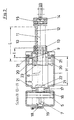
- the electromotive Actuator for the central locking of a motor vehicle a housing consisting of a first housing part (1) and a second housing part (2).
- an electric motor (3) is fixed, which carries a motor pinion (4) on its motor shaft.
- This Motor pinion (4) is part of a gear assembly, the further comprising a gear (5) serving as a spoked gear is formed, as is apparent from Figure 5.
- This spoke gear (5) is non-rotatable with a shaft (6) connected, which also acts as a torsion bar.
- the Spoked gear (5) is in common with the shaft (6) molded in one piece from plastic.
- Integral with the spokes of the spoked gear (5) is a toothing (7) formed in engages a torsion spring, which in a Torsionsfederkassette (8) is arranged.
- This torsion spring causes the rotation of the shaft (6) in the de-energized state the electric motor (3) such that a push rod (12) pulled as far as possible into the interior of the housing becomes.
- the shaft (6) On a sectionurnfang the shaft (6) is an external thread (9) arranged, as is apparent from the figure 2. This external thread (9) on the outer circumference the shaft (6) engages in a mating thread (10), the as an internal thread in a bore (11) of the push rod (12) is formed.
- the push rod (12) is longitudinally displaceable in a labyrinth seal (13) of the housing stored.
- the Labyrinth seal is integral with the plastic parts formed of the first and second housing part (1, 2).
- a button (14) is formed, which is a replaceable and thus to the respective application the electromotive actuator according to the invention adaptable coupling part (15) carries.
- the shaft (6) For axial and radial bearing of the shaft (6) in the housing, the shaft (6) on the one hand a storage area (16) in a constriction (17) of the Housing is arranged. Furthermore, the shaft (6) beyond the toothing (7) has an extension (18), which in a further shaft bearing (19) of the housing is. Thus, the shaft (6) on both sides of the Spoked gear (5) stored in the housing.
- the push rod (12) carries inside the housing two opposite stop elements (20) which are box-shaped and in one piece injection-molded with the push rod (12) made of plastic are.
- the box shape of the teeing elements (20) forms thus a four-bar linkage with film hinge, with housing stops (21) interacts.
- the order, consisting of the stop elements (20) and the housing stops (21), is then effective, when the push rod (12) in the housing on the End stops is moved.
- These resilient stop elements (20) should beat the push rod (12) to cushion on the case and a sudden and excessive Avoid torsion of the shaft (6).
- the two housing parts (1, 2) are through Locking connections (24) connected to each other.
- plug contacts (25) are in the housing wall and inserted through the housing wall in such a way that they continue to be plugged into the electric motor (3) can be and the electrical contact of the Electric motor with the remaining parts of a motor vehicle electrical system cause.
- the plug contacts (25) are to protect against mechanical damage in one Plug basket (26) integral with the housing parts (1, 2) arranged.
- the stroke of the push rod (12) in the housing is marked with (H) in FIG.
- the length of the Counter thread (10) of the push rod (12) is in the same Figure marked with (L).
- the length of the thread (9) of the shaft (6) is marked (I) in the same figure.
- the length (L) of the counter thread (10) is greater than the stroke (H) of Push rod (12) in the housing, but at least the same size as this hub.
- the Length (I) of the thread (9) is much smaller than the Length (L) of the counter thread (10), and it is the thread (9) facing away from the spoke gear (5)
- Side of the shaft (6) arranged so that between the thread (9) and the spoked gear (5) Shaft region of the shaft (6) is formed, the no thread and thus a torsion of the shaft (6) in the area between the spoke gear (5) and allows the thread (9).
Landscapes
- Engineering & Computer Science (AREA)
- General Engineering & Computer Science (AREA)
- Mechanical Engineering (AREA)
- Lock And Its Accessories (AREA)
- Connection Of Motors, Electrical Generators, Mechanical Devices, And The Like (AREA)
- Power-Operated Mechanisms For Wings (AREA)
Claims (13)
- Mécanisme de commande à moteur électrique pour véhicules automobiles, en particulier pour des verrouillages centralisés,caractérisé en ce quecomprenant un boítier (1, 2),comprenant un moteur électrique (3) qui entraíne un arbre (6) d'une seule pièce avec un pas de vis (9), ledit pas de vis (9) étant réalisé comme filetage sur la périphérie extérieure de l'arbre (6),comprenant une tige de poussée (12) qui engage le pas de vis (9) de l'arbre (6) au moyen d'un pas de vis complémentaire (10),dans lequel la tige de poussée (12) est guidée en déplacement longitudinal dans le boítier (1, 2),dans lequel la longueur (L) du pas de vis complémentaire (10) de la tige de poussée (12) est au moins égale à la course (H) de la tige de poussée (12) par rapport au boítier (1, 2),dans lequel la longueur (1) du pas de vis (9) de l'arbre (6) est inférieure à la longueur du pas de vis complémentaire (10) de la tige de poussée (12),dans lequel le pas de vis (9) de l'arbre (6) est agencé côté sortie de l'arbre (6), de sorte qu'il en résulte une zone d'arbre exempte de pas de vis,la zone exempte de pas de vis de l'arbre réalisé en matière plastique permet une torsion de l'arbre (6) lors du mouvement de la tige de poussée (12) en direction de butées de boítier (21) afin d'encaisser l'excès du couple de rotation que le moteur électrique (3) engendre lors du mouvement de la tige de poussée (12) vers l'une des butées de boítier, grâce à quoi un endommagement du mécanisme de commande est empêché dans cet état de fonctionnement.
- Mécanisme de commande à moteur électrique selon la revendication 1, caractérisé en ce que la longueur (I) du pas de vis (9) de l'arbre (6) s'élève approximativement à un tiers de la longueur (L) du pas de vis complémentaire (10) de la tige de poussée (12).
- Mécanisme de commande à moteur électrique selon la revendication 1, caractérisé en ce que le pas de vis (9) de l'arbre (6) présente trois à cinq pas, de préférence quatre pas.
- Mécanisme de commande à moteur électrique selon la revendication 1, caractérisé en ce que le pas de vis (9) de l'arbre (6) ne s'étend que sur une circonférence partielle de l'arbre (6).
- Mécanisme de commande à moteur électrique selon la revendication 1, caractérisé en ce qu'entre le moteur électrique (3) et l'arbre (6), il est prévu un agencement à engrenages dont le pignon de moteur (4) entraíne une roue dentée (5) reliée solidaire en rotation à l'arbre (6) et en ce que le pas de vis (9) est agencé sur le côté de l'arbre (6) qui est détourné de la roue dentée (5).
- Mécanisme de commande à moteur électrique selon la revendication 5, caractérisé en ce que la roue dentée (5) est une roue dentée à rayons et en ce que les rayons de la roue dentée (5) présentent une denture (7) qui s'engage dans un ressort de torsion d'une cassette (8) à ressort de torsion.
- Mécanisme de commande à moteur électrique selon la revendication 5, caractérisé en ce que des deux côtés de la roue dentée (5) est prévue une zone de palier (16) ou un prolongement (18) de l'arbre (6) qui correspond à un étranglement (17) du boítier ou à un palier d'arbre (19).
- Mécanisme de commande à moteur électrique selon la revendication 1, caractérisé en ce que le pas de vis (9) de l'arbre (6) est un filetage et en ce que le pas de vis complémentaire (10) de la tige de poussée (12) est un taraudage qui est ménagé dans un perçage (11) de la tige de poussée (12).
- Mécanisme de commande à moteur électrique selon la revendication 1, caractérisé en ce que la tige de poussée (12) présente des éléments de butée (20) qui coopèrent avec des butées de boítier (21).
- Mécanisme de commande à moteur électrique selon la revendication 9, caractérisé en ce que les éléments de butée (20) sont réalisés en forme de caisson dans le sens d'un quadrilatère articulé avec des charnières à bandes
- Mécanisme de commande à moteur électrique selon la revendication 1, caractérisé en ce que l'arbre (6) présente sur la face détournée du pas de vis (9) une bride d'arbre (22) qui coopère avec une face frontale (23) de la tige de poussée (12).
- Mécanisme de commande à moteur électrique selon la revendication 1, caractérisé en ce que des fiches mâles (24) électriques sont enfoncées dans la paroi de boítier et branchées en même temps dans le moteur électrique (3) pour réaliser la connexion électrique.
- Mécanisme de commande à moteur électrique selon la revendication 1, caractérisé en ce que la tige de poussée (12) est guidée dans un joint à labyrinthe (13) réalisé d'un seul tenant avec le boítier.
Applications Claiming Priority (2)
| Application Number | Priority Date | Filing Date | Title |
|---|---|---|---|
| DE19535437A DE19535437C2 (de) | 1995-09-23 | 1995-09-23 | Elektromotorischer Stellantrieb für Kraftfahrzeuge |
| DE19535437 | 1995-09-23 |
Publications (3)
| Publication Number | Publication Date |
|---|---|
| EP0764751A1 EP0764751A1 (fr) | 1997-03-26 |
| EP0764751B1 EP0764751B1 (fr) | 2001-05-16 |
| EP0764751B2 true EP0764751B2 (fr) | 2005-02-09 |
Family
ID=7773002
Family Applications (1)
| Application Number | Title | Priority Date | Filing Date |
|---|---|---|---|
| EP96114670A Expired - Lifetime EP0764751B2 (fr) | 1995-09-23 | 1996-09-13 | Positionneur à moteur électrique de véhicule |
Country Status (3)
| Country | Link |
|---|---|
| EP (1) | EP0764751B2 (fr) |
| DE (2) | DE19535437C2 (fr) |
| ES (1) | ES2159335T3 (fr) |
Families Citing this family (10)
| Publication number | Priority date | Publication date | Assignee | Title |
|---|---|---|---|---|
| DE29705380U1 (de) * | 1997-03-25 | 1997-06-12 | Hella Kg Hueck & Co, 59557 Lippstadt | Elektromotorischer Stellantrieb für Kraftfahrzeuge |
| DE19724877C2 (de) * | 1997-06-12 | 2001-06-28 | Hella Kg Hueck & Co | Elektromotorischer Stellantrieb für Kraftfahrzeuge mit Geräuschdämpfer |
| DE19908155A1 (de) * | 1999-02-25 | 2000-08-31 | Hella Kg Hueck & Co | Elektromotorische Stellvorrichtung für ein Kraftfahrzeug |
| DE10039839A1 (de) | 2000-08-10 | 2002-05-02 | Kiekert Ag | Lenkradschlosseinheiten |
| DE10239925B4 (de) * | 2002-08-30 | 2006-09-14 | Hella Kgaa Hueck & Co. | Stellantrieb für Kraftfahrzeuge |
| DE102004012573A1 (de) * | 2004-03-12 | 2005-10-06 | Kiekert Ag | Stellantrieb für Kraftfahrzeuge |
| DE102004063814A1 (de) * | 2004-12-30 | 2006-07-13 | Kiekert Ag | Adapter zur Verwendung mit einem elektronischen Kleinstantrieb |
| DE102008057860A1 (de) * | 2008-11-18 | 2010-07-22 | Bayerische Motoren Werke Aktiengesellschaft | Tankklappenmodul |
| DE102012218650A1 (de) | 2012-10-12 | 2014-02-06 | Kiekert Ag | Stelleinheit für ein Kraftfahrzeugschloss nebst Herstellungsverfahren |
| DE102014014620A1 (de) | 2014-09-25 | 2016-03-31 | Kiekert Aktiengesellschaft | Sicherungseinrichtung für ein elektronisches Gerät in einem Kraftfahrzeug |
Family Cites Families (16)
| Publication number | Priority date | Publication date | Assignee | Title |
|---|---|---|---|---|
| US2517373A (en) * | 1949-06-29 | 1950-08-01 | Air Associates Inc | Load limiting drive mechanism |
| US2778239A (en) * | 1953-04-06 | 1957-01-22 | Vaino A Hoover | Mechanical actuator |
| GB1005520A (en) * | 1964-02-05 | 1965-09-22 | North American Aviation Inc | An electrically operated extensible element |
| DE3247490A1 (de) * | 1982-12-22 | 1984-06-28 | Deutsche Babcock Werke AG, 4200 Oberhausen | Armatur |
| DE3309962A1 (de) * | 1983-03-19 | 1984-09-20 | Eberhard Dipl.-Ing. 2105 Seevetal Becker | Elektrisch fernbedienbares einsteckschloss |
| JPS60113856A (ja) * | 1983-11-26 | 1985-06-20 | Nippon Denso Co Ltd | 動力伝達装置 |
| DE8621592U1 (de) * | 1986-08-12 | 1986-10-09 | Kiekert Gmbh & Co Kg, 42579 Heiligenhaus | Stelltrieb für einen Kraftfahrzeug-Türverschluß |
| DE3631043C1 (en) * | 1986-09-12 | 1988-03-17 | Franz Dipl-Ing Schmidt | Door fastening, especially for motor vehicles |
| DE3631163A1 (de) * | 1986-09-12 | 1988-03-24 | Vdo Schindling | Elektromechanisches stellglied |
| JPH0453308Y2 (fr) * | 1986-10-31 | 1992-12-15 | ||
| EP0287860A3 (fr) * | 1987-03-31 | 1989-06-07 | Asmo Co., Ltd. | Mécanisme pour convertir un mouvement rotatif en mouvement alternatif |
| FR2623587B1 (fr) * | 1987-11-23 | 1992-04-03 | Rockwell Cim | Dispositif motoreducteur d'entrainement d'une piece a controle d'effort de securite |
| US4850466A (en) * | 1988-05-19 | 1989-07-25 | General Motors Corporation | Clutch for power door lock actuator |
| GB2224546A (en) * | 1988-08-23 | 1990-05-09 | Rockwell Automotive Body Syst | Vehicle door latch and like actuators |
| US4927203A (en) * | 1989-02-17 | 1990-05-22 | United Technologies Electro Systems, Inc. | Boot sealing and attachment means for automotive door lock actuators and the like |
| EP0512139A1 (fr) * | 1991-05-07 | 1992-11-11 | Siemens Aktiengesellschaft | Actionneur entraîné par un moteur électrique |
-
1995
- 1995-09-23 DE DE19535437A patent/DE19535437C2/de not_active Revoked
-
1996
- 1996-09-13 EP EP96114670A patent/EP0764751B2/fr not_active Expired - Lifetime
- 1996-09-13 DE DE59606899T patent/DE59606899D1/de not_active Expired - Lifetime
- 1996-09-13 ES ES96114670T patent/ES2159335T3/es not_active Expired - Lifetime
Also Published As
| Publication number | Publication date |
|---|---|
| ES2159335T3 (es) | 2001-10-01 |
| DE19535437A1 (de) | 1997-04-03 |
| DE59606899D1 (de) | 2001-06-21 |
| EP0764751A1 (fr) | 1997-03-26 |
| EP0764751B1 (fr) | 2001-05-16 |
| DE19535437C2 (de) | 2001-10-18 |
Similar Documents
| Publication | Publication Date | Title |
|---|---|---|
| DE69504907T2 (de) | Einstellvorrichtung des Spiegelgehäuses eines Fahrzeugrückblickspiegels. | |
| EP1404956B1 (fr) | Mecanisme de commande a moteur electrique, muni d'une vis sans fin | |
| EP0764751B2 (fr) | Positionneur à moteur électrique de véhicule | |
| EP2483572B1 (fr) | Joint coulissant | |
| DE102017115464A1 (de) | Überlastkupplung für einen Antriebsstrang | |
| DE102019133406A1 (de) | Schubstangenführungsbaugruppe, Lenkaktuator sowie Verfahren zur Herstellung einer Schubstangenführungsbaugruppe | |
| EP0802348B1 (fr) | Ensemble de transmission | |
| DE102012112514A1 (de) | Pedaleinheit für ein KFZ | |
| DE102018002905A1 (de) | Spindelantrieb für ein Verschlusselement eines Kraftfahrzeugs | |
| DE102019100153B4 (de) | Übertragungstrennmechanismus eines Untersetzungsgetriebes | |
| EP1633966B1 (fr) | Mecanisme de commande pour deplacement reversible d'un clapet de soupape | |
| DE202009014365U1 (de) | Rohrmotor für eine Verdunkelungsvorrichtung o.dgl. | |
| DE202007003713U1 (de) | Vorrichtung zum Verstellen von Sitzelementen | |
| EP1671001B1 (fr) | Serrure | |
| DE3626101A1 (de) | Drehbares antriebsbauteil fuer ein lenkgetriebe, insbesondere fuer kraftfahrzeuge | |
| DE102021103622A1 (de) | Dreh-getriebeanordnung zur vergrösserung des hartanschlag-motorweges | |
| EP2292447A2 (fr) | Crayon rotatif à roue libre | |
| EP1659250A1 (fr) | Fenêtre, porte ou analogue avec un renvoi de coin | |
| DE102020200266A1 (de) | Mit einem Kettenantrieb betätigbare schiebesteife Schubkette | |
| DE102019110902A1 (de) | Spindelantrieb für ein Verschlusselement eines Kraftfahrzeugs | |
| EP1764462B1 (fr) | Transmission pour une barre anti-panique | |
| DE102004052180B3 (de) | Abklappantrieb für einen Kfz-Außenrückblickspiegel | |
| EP4086414B1 (fr) | Agencement de cylindre de fermeture pourvu d'accouplement à poignée | |
| EP1057960A2 (fr) | Dispositif de manoeuvre | |
| DE4041314A1 (de) | Spielfreier zahnradantrieb |
Legal Events
| Date | Code | Title | Description |
|---|---|---|---|
| PUAI | Public reference made under article 153(3) epc to a published international application that has entered the european phase |
Free format text: ORIGINAL CODE: 0009012 |
|
| AK | Designated contracting states |
Kind code of ref document: A1 Designated state(s): DE ES FR GB IT |
|
| 17P | Request for examination filed |
Effective date: 19970701 |
|
| 17Q | First examination report despatched |
Effective date: 19990317 |
|
| GRAG | Despatch of communication of intention to grant |
Free format text: ORIGINAL CODE: EPIDOS AGRA |
|
| GRAG | Despatch of communication of intention to grant |
Free format text: ORIGINAL CODE: EPIDOS AGRA |
|
| GRAH | Despatch of communication of intention to grant a patent |
Free format text: ORIGINAL CODE: EPIDOS IGRA |
|
| ITF | It: translation for a ep patent filed | ||
| GRAH | Despatch of communication of intention to grant a patent |
Free format text: ORIGINAL CODE: EPIDOS IGRA |
|
| GRAA | (expected) grant |
Free format text: ORIGINAL CODE: 0009210 |
|
| AK | Designated contracting states |
Kind code of ref document: B1 Designated state(s): DE ES FR GB IT |
|
| PG25 | Lapsed in a contracting state [announced via postgrant information from national office to epo] |
Ref country code: GB Free format text: LAPSE BECAUSE OF FAILURE TO SUBMIT A TRANSLATION OF THE DESCRIPTION OR TO PAY THE FEE WITHIN THE PRESCRIBED TIME-LIMIT Effective date: 20010516 Ref country code: FR Free format text: LAPSE BECAUSE OF NON-PAYMENT OF DUE FEES Effective date: 20010516 |
|
| REF | Corresponds to: |
Ref document number: 59606899 Country of ref document: DE Date of ref document: 20010621 |
|
| GBT | Gb: translation of ep patent filed (gb section 77(6)(a)/1977) |
Effective date: 20010731 |
|
| REG | Reference to a national code |
Ref country code: ES Ref legal event code: FG2A Ref document number: 2159335 Country of ref document: ES Kind code of ref document: T3 |
|
| ET | Fr: translation filed | ||
| REG | Reference to a national code |
Ref country code: GB Ref legal event code: IF02 |
|
| PLBQ | Unpublished change to opponent data |
Free format text: ORIGINAL CODE: EPIDOS OPPO |
|
| PLBI | Opposition filed |
Free format text: ORIGINAL CODE: 0009260 |
|
| 26 | Opposition filed |
Opponent name: SIEMENS AG Effective date: 20020117 |
|
| PLBF | Reply of patent proprietor to notice(s) of opposition |
Free format text: ORIGINAL CODE: EPIDOS OBSO |
|
| PLBF | Reply of patent proprietor to notice(s) of opposition |
Free format text: ORIGINAL CODE: EPIDOS OBSO |
|
| PGFP | Annual fee paid to national office [announced via postgrant information from national office to epo] |
Ref country code: GB Payment date: 20040908 Year of fee payment: 9 Ref country code: FR Payment date: 20040908 Year of fee payment: 9 |
|
| PGFP | Annual fee paid to national office [announced via postgrant information from national office to epo] |
Ref country code: ES Payment date: 20040929 Year of fee payment: 9 |
|
| RAP2 | Party data changed (patent owner data changed or rights of a patent transferred) |
Owner name: HELLA KGAA HUECK & CO. |
|
| PUAH | Patent maintained in amended form |
Free format text: ORIGINAL CODE: 0009272 |
|
| STAA | Information on the status of an ep patent application or granted ep patent |
Free format text: STATUS: PATENT MAINTAINED AS AMENDED |
|
| 27A | Patent maintained in amended form |
Effective date: 20050209 |
|
| AK | Designated contracting states |
Kind code of ref document: B2 Designated state(s): DE ES FR GB IT |
|
| PG25 | Lapsed in a contracting state [announced via postgrant information from national office to epo] |
Ref country code: ES Free format text: LAPSE BECAUSE OF FAILURE TO SUBMIT A TRANSLATION OF THE DESCRIPTION OR TO PAY THE FEE WITHIN THE PRESCRIBED TIME-LIMIT Effective date: 20050520 |
|
| GBV | Gb: ep patent (uk) treated as always having been void in accordance with gb section 77(7)/1977 [no translation filed] |
Effective date: 20010516 |
|
| EN | Fr: translation not filed | ||
| PGFP | Annual fee paid to national office [announced via postgrant information from national office to epo] |
Ref country code: IT Payment date: 20060930 Year of fee payment: 11 |
|
| PG25 | Lapsed in a contracting state [announced via postgrant information from national office to epo] |
Ref country code: IT Free format text: LAPSE BECAUSE OF NON-PAYMENT OF DUE FEES Effective date: 20070913 |
|
| PGFP | Annual fee paid to national office [announced via postgrant information from national office to epo] |
Ref country code: DE Payment date: 20150908 Year of fee payment: 20 |
|
| REG | Reference to a national code |
Ref country code: DE Ref legal event code: R071 Ref document number: 59606899 Country of ref document: DE |