EP0763407B1 - Equipement de séparation de poses au sein d'une machine de découpe d'éléments en plaque - Google Patents
Equipement de séparation de poses au sein d'une machine de découpe d'éléments en plaque Download PDFInfo
- Publication number
- EP0763407B1 EP0763407B1 EP96111744A EP96111744A EP0763407B1 EP 0763407 B1 EP0763407 B1 EP 0763407B1 EP 96111744 A EP96111744 A EP 96111744A EP 96111744 A EP96111744 A EP 96111744A EP 0763407 B1 EP0763407 B1 EP 0763407B1
- Authority
- EP
- European Patent Office
- Prior art keywords
- longitudinal
- strips
- tool
- pressers
- orifices
- Prior art date
- Legal status (The legal status is an assumption and is not a legal conclusion. Google has not performed a legal analysis and makes no representation as to the accuracy of the status listed.)
- Expired - Lifetime
Links
- 238000005520 cutting process Methods 0.000 title description 6
- 238000000926 separation method Methods 0.000 claims abstract description 12
- 238000011144 upstream manufacturing Methods 0.000 claims description 10
- 238000000034 method Methods 0.000 abstract 1
- 239000000543 intermediate Substances 0.000 description 13
- 239000011111 cardboard Substances 0.000 description 3
- 230000000694 effects Effects 0.000 description 3
- 238000009434 installation Methods 0.000 description 3
- 239000000463 material Substances 0.000 description 3
- 239000011087 paperboard Substances 0.000 description 3
- 238000012423 maintenance Methods 0.000 description 2
- 238000004519 manufacturing process Methods 0.000 description 2
- BASFCYQUMIYNBI-UHFFFAOYSA-N platinum Chemical compound [Pt] BASFCYQUMIYNBI-UHFFFAOYSA-N 0.000 description 2
- 239000002699 waste material Substances 0.000 description 2
- 241001080024 Telles Species 0.000 description 1
- 239000000853 adhesive Substances 0.000 description 1
- 238000004026 adhesive bonding Methods 0.000 description 1
- 230000001070 adhesive effect Effects 0.000 description 1
- 229910052782 aluminium Inorganic materials 0.000 description 1
- XAGFODPZIPBFFR-UHFFFAOYSA-N aluminium Chemical compound [Al] XAGFODPZIPBFFR-UHFFFAOYSA-N 0.000 description 1
- 235000015241 bacon Nutrition 0.000 description 1
- 238000005452 bending Methods 0.000 description 1
- 239000003086 colorant Substances 0.000 description 1
- 230000007423 decrease Effects 0.000 description 1
- 238000013461 design Methods 0.000 description 1
- 229920001971 elastomer Polymers 0.000 description 1
- 239000000806 elastomer Substances 0.000 description 1
- 239000006260 foam Substances 0.000 description 1
- 230000014509 gene expression Effects 0.000 description 1
- 238000005259 measurement Methods 0.000 description 1
- 229910052751 metal Inorganic materials 0.000 description 1
- 239000002184 metal Substances 0.000 description 1
- 238000012986 modification Methods 0.000 description 1
- 230000004048 modification Effects 0.000 description 1
- 238000012544 monitoring process Methods 0.000 description 1
- 230000035515 penetration Effects 0.000 description 1
- 229910052697 platinum Inorganic materials 0.000 description 1
- 238000003825 pressing Methods 0.000 description 1
- 230000000717 retained effect Effects 0.000 description 1
- 230000000630 rising effect Effects 0.000 description 1
- 239000000725 suspension Substances 0.000 description 1
- 239000002023 wood Substances 0.000 description 1
Images

Classifications
-
- B—PERFORMING OPERATIONS; TRANSPORTING
- B26—HAND CUTTING TOOLS; CUTTING; SEVERING
- B26D—CUTTING; DETAILS COMMON TO MACHINES FOR PERFORATING, PUNCHING, CUTTING-OUT, STAMPING-OUT OR SEVERING
- B26D1/00—Cutting through work characterised by the nature or movement of the cutting member or particular materials not otherwise provided for; Apparatus or machines therefor; Cutting members therefor
-
- B—PERFORMING OPERATIONS; TRANSPORTING
- B26—HAND CUTTING TOOLS; CUTTING; SEVERING
- B26D—CUTTING; DETAILS COMMON TO MACHINES FOR PERFORATING, PUNCHING, CUTTING-OUT, STAMPING-OUT OR SEVERING
- B26D7/00—Details of apparatus for cutting, cutting-out, stamping-out, punching, perforating, or severing by means other than cutting
- B26D7/18—Means for removing cut-out material or waste
- B26D7/1845—Means for removing cut-out material or waste by non mechanical means
- B26D7/1863—Means for removing cut-out material or waste by non mechanical means by suction
-
- B—PERFORMING OPERATIONS; TRANSPORTING
- B26—HAND CUTTING TOOLS; CUTTING; SEVERING
- B26D—CUTTING; DETAILS COMMON TO MACHINES FOR PERFORATING, PUNCHING, CUTTING-OUT, STAMPING-OUT OR SEVERING
- B26D7/00—Details of apparatus for cutting, cutting-out, stamping-out, punching, perforating, or severing by means other than cutting
- B26D7/18—Means for removing cut-out material or waste
- B26D7/1818—Means for removing cut-out material or waste by pushing out
-
- B—PERFORMING OPERATIONS; TRANSPORTING
- B26—HAND CUTTING TOOLS; CUTTING; SEVERING
- B26D—CUTTING; DETAILS COMMON TO MACHINES FOR PERFORATING, PUNCHING, CUTTING-OUT, STAMPING-OUT OR SEVERING
- B26D7/00—Details of apparatus for cutting, cutting-out, stamping-out, punching, perforating, or severing by means other than cutting
- B26D7/18—Means for removing cut-out material or waste
- B26D2007/1881—Means for removing cut-out material or waste using countertools
-
- Y—GENERAL TAGGING OF NEW TECHNOLOGICAL DEVELOPMENTS; GENERAL TAGGING OF CROSS-SECTIONAL TECHNOLOGIES SPANNING OVER SEVERAL SECTIONS OF THE IPC; TECHNICAL SUBJECTS COVERED BY FORMER USPC CROSS-REFERENCE ART COLLECTIONS [XRACs] AND DIGESTS
- Y10—TECHNICAL SUBJECTS COVERED BY FORMER USPC
- Y10T—TECHNICAL SUBJECTS COVERED BY FORMER US CLASSIFICATION
- Y10T225/00—Severing by tearing or breaking
- Y10T225/30—Breaking or tearing apparatus
-
- Y—GENERAL TAGGING OF NEW TECHNOLOGICAL DEVELOPMENTS; GENERAL TAGGING OF CROSS-SECTIONAL TECHNOLOGIES SPANNING OVER SEVERAL SECTIONS OF THE IPC; TECHNICAL SUBJECTS COVERED BY FORMER USPC CROSS-REFERENCE ART COLLECTIONS [XRACs] AND DIGESTS
- Y10—TECHNICAL SUBJECTS COVERED BY FORMER USPC
- Y10T—TECHNICAL SUBJECTS COVERED BY FORMER US CLASSIFICATION
- Y10T225/00—Severing by tearing or breaking
- Y10T225/30—Breaking or tearing apparatus
- Y10T225/329—Plural breakers
-
- Y—GENERAL TAGGING OF NEW TECHNOLOGICAL DEVELOPMENTS; GENERAL TAGGING OF CROSS-SECTIONAL TECHNOLOGIES SPANNING OVER SEVERAL SECTIONS OF THE IPC; TECHNICAL SUBJECTS COVERED BY FORMER USPC CROSS-REFERENCE ART COLLECTIONS [XRACs] AND DIGESTS
- Y10—TECHNICAL SUBJECTS COVERED BY FORMER USPC
- Y10T—TECHNICAL SUBJECTS COVERED BY FORMER US CLASSIFICATION
- Y10T225/00—Severing by tearing or breaking
- Y10T225/30—Breaking or tearing apparatus
- Y10T225/371—Movable breaking tool
- Y10T225/379—Breaking tool intermediate spaced work supports
- Y10T225/386—Clamping supports
-
- Y—GENERAL TAGGING OF NEW TECHNOLOGICAL DEVELOPMENTS; GENERAL TAGGING OF CROSS-SECTIONAL TECHNOLOGIES SPANNING OVER SEVERAL SECTIONS OF THE IPC; TECHNICAL SUBJECTS COVERED BY FORMER USPC CROSS-REFERENCE ART COLLECTIONS [XRACs] AND DIGESTS
- Y10—TECHNICAL SUBJECTS COVERED BY FORMER USPC
- Y10T—TECHNICAL SUBJECTS COVERED BY FORMER US CLASSIFICATION
- Y10T83/00—Cutting
- Y10T83/202—With product handling means
- Y10T83/2092—Means to move, guide, or permit free fall or flight of product
- Y10T83/2183—Product mover including gripper means
- Y10T83/2185—Suction gripper
Definitions
- the present invention relates to separation equipment of poses within a machine for cutting plate elements such as, for example, sheets of paper or cardboard.
- a machine according to the preamble of claim 1 is described in CH-A-324 448.
- Each machine is, among other things, used to cut into each sheet one or more poses, also called formats, which, after folding and gluing, can be transformed into boxes.
- Each pose generally includes the six sides of a box, some edges being complete with adhesive or closing tabs.
- Such a machine usually first comprises a station introduction in which the sheets, possibly pre-printed, are apprehended one by one from the top of a stack to be sent to a margin table where they are positioned against front cleats and lateral.
- the sheet can then be grasped at its front edge by a series of clamps mounted along a crossbar, each end of which is attached to a side chain train carrying the bar, so the sheet, in the following treatment stations.
- This station usually comprises a platen press, the stationary upper plate carries a plate provided with a plurality of straight and curved slender knives. If desired, the cutting station can be preceded by a printing station also with platinum.
- the sheet is then normally brought to a station where the waste, i.e. unused areas of the sheet enters the tabs or between formats, are pinched by upper needles and lower to be dragged down into a tray.
- the sheet is then brought to the separation station of poses, where the attachment points between the poses and the sheet are broken at by means of a male upper plane tool descending into a lower plane tool female, so as to release each of the poses that fall on top of an underlying stack.
- the residual sheet is finally entrained in an exit station where it is released by the clamp bar.
- the sheet is brought flat on a lower tool in the form of a perforated horizontal board according to the perimeter of the poses to eject.
- this lower tool is therefore in the form of a grid with each bar longitudinal and transverse reproduces the shape of the intermediate bands separating the poses from each other.
- the upper implement intended to be lowered sequentially into the implement lower comprises on the one hand pushers, that is to say wooden skids or foam, each attached to the tool above a pose from which it resumes the outline is slightly smaller.
- This superior tool also includes pressers, i.e. bars or studs located respectively above the intermediate bands and mounted on elastic supports so as to press each strip against its corresponding bar of the grid of the lower tool during the separation of the poses.
- the residual sheet after separation of the poses also occurs under the form of a grid of paper or cardboard initially supported by each bars of the lower tool.
- the bands transverse intermediates in the direction of movement are no longer supported only at their ends and hang down their midpoints.
- the central arrows can reach 1 or 2 cm, making these parts will then hook onto the other bars of the tool grid inferior.
- the residual leaves have then tendency to tear and fall back on stacks of poses so untimely.
- the object of the present invention is to improve separation equipment that obviates the problem of rupture of the residual sheet when it is removed.
- the design of this improvement must however keep it simple for reliable operation and low cost of production.
- the longitudinal pressers are changed from so that you can take it up when the tool is raised upper, between two-thirds and four-fifths upstream of the leaf residual.
- the low points of the transverse intermediate bands bending are then clearly above the transverse bars of the lower tool.
- the depression is adjusted to a value just sufficient for only compensate for the weight of the sheet without creating an undue friction force which could cause cause a break in the clamp bar.
- the effect of this depression decreases as the leaf is withdrawn by successive opening of the orifices, always only exerting a force of just sufficient lifting.
- the pressers located above the longitudinal intermediate bands and side bands are are in the form of longitudinal cylinders closed in two ends, of lengths substantially identical to those of the tools, and of which their flat lower faces have a series of suction orifices.
- the use of cylinder as longitudinal pressers greatly simplifies the connection of the orifices to the source of vacuum.
- the undersides planes constitute homogeneous surfaces against which the longitudinal strips of the residual leaf when removed.
- the distance (a) between the downstream end of the pressure cylinder and the start of the series of orifices is between a quarter and a third of the length of the cylinder. This allows for a curvature softened between the raised sheet and the clamp bar located slightly above of the lower tool.
- the series of orifices formed in the two pressure rollers located above each of the two side bands are offset inward from the center line of the face lower. It has indeed been observed that the lowering of the transverse bands causes a tightening of the residual leaf. This mismatch of the two series of holes on each side ensures that the two bands side are always correctly understood.
- a series includes a dozen orifices with a diameter of the order of 1 millimeter and spaced 5 to 15 centimeters.
- a tank-distributor in the form of a cylinder closed at both ends is arranged transversely a little above longitudinal pressure cylinders, and is connected on the one hand to a pump with vacuum and on the other hand to each of the pressing cylinders by a flexible pipe, by example describing a loop.
- This arrangement is relatively simple to realize, and allow the installation of flexible supply pipes for compensate for the relative movements of the pressure rollers with respect to the upper tool, these pipes being easy to access for monitoring and maintenance.
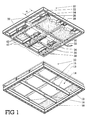
- the installation separation equipment comprises a lower tool 10 and upper tool 20.
- the lower tool 10 is based on a grid tool 12 in the form a board usually made of wood in which a plurality has been provided openwork 14 corresponding to the layout of the poses cut from a sheet in a "double-cut" mode.
- the poses are surrounded by two side bands, a rear band and a band front taken by the grippers, and these poses are separated between them by intermediate longitudinal and lateral width bands minimum of 5 mm.
- the tool 12 presents itself in the form of a grid whose transverse bars 13 and longitudinal 15 resume substantially the shape of the corresponding intermediate bands, but in having a slightly smaller width.
- the grid tool 12 is supported by a plurality of cross-supports 16 located under the front bar, under each of the transverse bars 13 and under the rear bar. These support sleepers 16 themselves rest on a lower frame 18 removable. Alternatively, these cross-supports 16 are an integral part of the box 18.
- these frames and crosspieces are made from profiled metal bars, preferably aluminum for their relative lightness.
- the higher than wide profile of these profiles ensures great rigidity in the vertical direction of the tool 10.
- the external faces of the crosspieces upstream and downstream of the frame have a groove making it possible to exit then to reinstall this tool in the station by passing it through a side window and the sliding of two upstream and downstream bacon belonging to the fixing the station.
- the frame is further completed in its four points of centering studs with conical part and receiving locking pins. We can easily remove this lower tool 10 to change the grid tool 12 into function of the new installation layout of the production series next.
- the upper tool 20 also includes a rectangular frame 22 stiffened by beams 24, both also made from particularly rigid profiles in the vertical direction.
- Each pusher 28 is in vertical correspondence with a hole 14 in the lower grid tool 12.
- These pushers 28 are in the form of wooden plates or blocks rigid elastomer, possibly hollowed out in the middle, but the contour resumes that of one of the poses cut from the sheet, so the outline of its opening 14 in correspondence.
- the longitudinal pressers 36 are connected to the beam 24 of the frame 22 by a pair of elastic telescopic supports 39: a upstream and downstream.
- a support 39 may be a rod whose end lower is fixed to the presser 36 and whose upper end slides in a tab connected to the crosspiece 24.
- a spring coaxial with the rod acts between the presser 36 and the tab so as to compress when this presser closer to its spar.
- the length of the rod is such that the face bottom of the presser 36 is located slightly below, on the order of 5 to 10 mm, from the underside of the pushers 28.
- the transverse pressers 40 are mounted analogously to the spar 24 by supports elastic telescopic 42. These pressers 36 and 40 being located between the pushers 28, so they are found in vertical correspondence respectively with the bars 15 and 13 of the grid tool 12.
- the longitudinal pressers 36 have a series of suction ports 38.
- these pressers 36 are made by means of tubes of rectangular section, and closed in their extremities. The interior of each of these tubes is connected by a flexible tube 34 to a distributor-reservoir 30 itself connected to a vacuum pump by a supply conduit 32.
- This distributor-reservoir 30 is provided under the form of a tube closed at both ends and arranged transversely to the longitudinal pressers 36, and this between the pushers 28 and the side members 24.
- the tubes 34 are made of flexible material, and can even take the form of a loop, so as to easily deform during the movement of the longitudinal pressers 36 relative to the side member 24.
- each longitudinal presser 36 presents the same series of a dozen suction ports 38, each orifice having a diameter on the order of 1 mm and being spaced on the order of 5 to 15 cm from each other.
- the depression applied in the distributor-reservoir 30 is such that, taking into account the pressure drops in the flexible tubes 34, a vacuum of the order of 500 to 700 is obtained millibars at the suction ports 38.
- the series of orifices 38 do not start from the downstream end longitudinal pressers 36 only from a distance (a) of the order of third or even a quarter of the length of said presser 36.
- FIGS. 2a to 2c in which have been reported the same reference numerals in Figure 1.
- FIG. 2a illustrates how, the upper tool 20 being raised, a gripper bar 5 brings a sheet 1 on top of the fixed lower tool 10, and more particularly on the top of the grid tool 12.
- the function suction of the longitudinal pressers 36 has no effect at this time.
- FIG. 2b illustrates how the upper tool 20 is lowered in the lower tool 10 until the pushers 28 enter the openings 14. Just before this return of the pushers, the longitudinal pressers 36 and transverse tightened the intermediate strips against the bars in correspondence of the tool-grid 12. The penetration of the pushers 28 into the openwork 14 causes the material bridges connecting each laying on the sheet. This rupture is accompanied by an ejection of the poses 3 towards the bottom which fall squared on top of their respective pile 7.
- FIG. 2c illustrates the ascent of the upper tool 20 and the start of the clamp bar 5 to pull the residual sheet 1 'towards the output station.
- the presence of orifices aspirants 38 causes atmospheric pressure to plate this perforated sheet 1 ' against the longitudinal pressers 36, this sheet therefore rising with the tool upper 20.
- the intermediate bands transverse 2 in suspension are then found clearly above the transverse bars 13 with which they can no longer interfere.
- the residual sheet 1 'therefore slides along the pressers longitudinal 36 raised, the upstream holes being re-opened as and sheet advance measurement, which automatically readjusts the effect of the atmospheric pressure on the downstream part of this residual sheet.
- the absence of suction ports in the upstream portion of the longitudinal presser 36 allows the sheet to describe a softened curve towards the clamp bar 5 situated at a lower level, practically at the level of the upper face of the tool 10.
Landscapes
- Life Sciences & Earth Sciences (AREA)
- Forests & Forestry (AREA)
- Engineering & Computer Science (AREA)
- Mechanical Engineering (AREA)
- Details Of Cutting Devices (AREA)
- Making Paper Articles (AREA)
- Perforating, Stamping-Out Or Severing By Means Other Than Cutting (AREA)
- Processing Of Stones Or Stones Resemblance Materials (AREA)
- Sheets, Magazines, And Separation Thereof (AREA)
- Prostheses (AREA)
- Polishing Bodies And Polishing Tools (AREA)
- Finish Polishing, Edge Sharpening, And Grinding By Specific Grinding Devices (AREA)
- Mechanical Treatment Of Semiconductor (AREA)
Applications Claiming Priority (3)
| Application Number | Priority Date | Filing Date | Title |
|---|---|---|---|
| CH2262/95 | 1995-08-04 | ||
| CH02262/95A CH690844A5 (fr) | 1995-08-04 | 1995-08-04 | Equipement de séparation de poses au sein d'une machine de découpe d'éléments en plaque . |
| CH226295 | 1995-08-04 |
Publications (2)
| Publication Number | Publication Date |
|---|---|
| EP0763407A1 EP0763407A1 (fr) | 1997-03-19 |
| EP0763407B1 true EP0763407B1 (fr) | 2001-12-19 |
Family
ID=4229666
Family Applications (1)
| Application Number | Title | Priority Date | Filing Date |
|---|---|---|---|
| EP96111744A Expired - Lifetime EP0763407B1 (fr) | 1995-08-04 | 1996-07-22 | Equipement de séparation de poses au sein d'une machine de découpe d'éléments en plaque |
Country Status (14)
| Country | Link |
|---|---|
| US (1) | US5810233A (da) |
| EP (1) | EP0763407B1 (da) |
| JP (1) | JP2866061B2 (da) |
| KR (1) | KR100206078B1 (da) |
| CN (1) | CN1058208C (da) |
| AT (1) | ATE211048T1 (da) |
| AU (1) | AU675401B1 (da) |
| BR (1) | BR9603275A (da) |
| CA (1) | CA2182639C (da) |
| CH (1) | CH690844A5 (da) |
| DE (1) | DE69618116T2 (da) |
| DK (1) | DK0763407T3 (da) |
| ES (1) | ES2169177T3 (da) |
| TW (1) | TW436421B (da) |
Families Citing this family (42)
| Publication number | Priority date | Publication date | Assignee | Title |
|---|---|---|---|---|
| CH691035A5 (fr) * | 1995-04-18 | 2001-04-12 | Bobst Sa | Outil pour machine de découpe d'éléments en plaque, et équipement associé. |
| CA2259785C (en) | 1999-01-19 | 2008-07-29 | Peter E. Sandford | Jogger member, system and method for mounting jogger members and female and male blanking dies provided therewith |
| US6666810B1 (en) * | 1999-06-11 | 2003-12-23 | Honeywell International Inc. | Device for controllable stretching of thin materials |
| CH693502A5 (fr) * | 1999-08-02 | 2003-09-15 | Bobst Sa | Outil universel d'éjection. |
| CA2286981C (en) * | 1999-10-20 | 2008-03-18 | Peter E. Sandford | Methods for erection of female blanking die and universal press frames for use in such methods |
| CH693787A5 (fr) * | 1999-10-26 | 2004-02-13 | Bobst Sa | Procédé pour préparer un système d'outils de façonnage, table de réglage pour mettre en oeuvre ce procédé et ensemble d'éléments pour préparer une forme supérieure d'éjection. |
| CH694086A5 (fr) * | 2000-05-16 | 2004-07-15 | Bobst Sa | Presse de façonnage. |
| WO2002036471A2 (en) * | 2000-11-01 | 2002-05-10 | Joseph Mcardle (Exporting) Limited | A sliding jogger and a blanking tool incorporating such jogger |
| DE10065457B4 (de) * | 2000-12-28 | 2007-04-26 | Karl Marbach Gmbh & Co. Kg | Verfahren und Vorrichtung zur Trennung von Nutzen und Abfall eines gestanzten oder geschnittenen Materialbogens sowie Anlage zur Herstellung von Nutzen aus einem Materialbogen |
| ATE294680T1 (de) * | 2001-03-08 | 2005-05-15 | Jordan David Hedley | Ausbrechwerkzeug aus kunsstoffschaum |
| US6692425B2 (en) | 2001-04-30 | 2004-02-17 | Sdc Innovations, Inc. | Folding presser assembly |
| US6659927B2 (en) | 2001-04-30 | 2003-12-09 | Sdc Innovations, Inc. | Folding presser assembly |
| US6589148B2 (en) | 2001-08-08 | 2003-07-08 | Michael P. Tarka | Moveable presser rail assembly |
| US6966873B2 (en) * | 2001-12-26 | 2005-11-22 | Blanking Systems, Inc. | Flush mounted presser assembly |
| US6792840B2 (en) | 2002-02-08 | 2004-09-21 | Atlas Die Llc | Folding plunger assembly for blanking system |
| CH695444A5 (fr) * | 2002-03-28 | 2006-05-31 | Bobst Sa | Organe de support, de fixation et de renforcement d'un outil plan utilise dans une station d'ejection de dechets d'une presse a decouper. |
| CH695854A5 (fr) * | 2002-09-12 | 2006-09-29 | Bobst Sa | Procédé et dispositif de séparation de poses dans une machine de découpe d'éléments en plaque. |
| DE10251780A1 (de) * | 2002-11-05 | 2004-05-19 | Heidelberger Druckmaschinen Ag | Bogenstanz- und -prägemaschine |
| DE10259556A1 (de) * | 2002-12-19 | 2004-07-01 | Heidelberger Druckmaschinen Ag | Bogenstanz- und -prägemaschine |
| TWI246452B (en) * | 2003-10-14 | 2006-01-01 | Bobst Sa | Blanking station of a diecutting press |
| JP3141440U (ja) * | 2007-12-14 | 2008-05-08 | 株式会社メイク・ア・ボックス | 転移位置決め治具 |
| CN101791877B (zh) * | 2009-01-29 | 2014-02-19 | 株式会社纸制品制造 | 冲孔机的面板对位用部件及使用了该部件的面板安装方法 |
| US20100192742A1 (en) * | 2009-01-30 | 2010-08-05 | Michigan Lasercut | Stripping apparatus |
| US8770103B2 (en) * | 2009-12-08 | 2014-07-08 | Blanking Systems, Inc. | Presser assembly having a presser and an improved mounting arrangement for mounting a pressing member to the presser |
| CN101870182B (zh) * | 2010-06-09 | 2011-12-14 | 昆明矢量科技开发有限公司 | 模切纸品清废分离一体机 |
| IT1401265B1 (it) * | 2010-08-06 | 2013-07-18 | Gallucci | Dispositivo per lo scarico, da un piano di lavoro, di articoli piani nei quali sono ricavate, mediante taglio e/o incisione, porzioni su cui sono riprodotti disegni e/o scritte |
| CN102601818A (zh) * | 2012-03-22 | 2012-07-25 | 瑞安市东腾机械有限公司 | 对模切后的纸张进行废边清理的方法及实现该方法的设备 |
| US9038999B2 (en) * | 2012-08-10 | 2015-05-26 | Ford Global Technologies, Llc | Fixture assembly for forming prototype parts on an incremental forming machine |
| DE202012104394U1 (de) * | 2012-11-14 | 2014-02-17 | Franz Vossen | Vorrichtung zum Stanzen von blattartigen Kartonwerkstoffen |
| DE102013215706A1 (de) * | 2013-08-08 | 2015-02-12 | Bielomatik Leuze Gmbh + Co. Kg | Transfer-Stanzen |
| JP6117755B2 (ja) | 2014-09-22 | 2017-04-19 | ファナック株式会社 | 予め切断された基板の引っ掛かりを解除する装置、ロボット、およびロボットシステム |
| CN104827517A (zh) * | 2015-05-05 | 2015-08-12 | 佛山华工祥源环保包装有限公司 | 一种吸附式飞边裁切去除装置及其去飞边工艺 |
| CN106695983A (zh) * | 2016-12-30 | 2017-05-24 | 重庆皖渝纸制品有限公司 | 纸板余料分离装置 |
| US20180186113A1 (en) * | 2017-01-03 | 2018-07-05 | Fiskars Brands, Inc. | User-defined box creation apparatus |
| CN108996214B (zh) * | 2018-06-29 | 2023-08-29 | 苏州富强科技有限公司 | 一种分离结构 |
| JP6762446B1 (ja) * | 2020-02-20 | 2020-09-30 | 株式会社スリーブイ | ブランキング下型、下型基板、ブランキング型、及び、下型基板の交換方法 |
| CN115042241B (zh) * | 2022-07-07 | 2024-03-19 | 湖北纽凯伦轨道交通新材料有限公司 | 一种高效性防水板的分切装置 |
| US20260084331A1 (en) * | 2022-09-15 | 2026-03-26 | Bobst Mex Sa | Hybrid blanking frame, blanking system, and sheet processing machine |
| CN115741863B (zh) * | 2022-11-17 | 2025-11-14 | 义乌清越光电科技有限公司 | 一种基板加工设备 |
| US12257805B2 (en) | 2023-01-18 | 2025-03-25 | Blanking Systems, Inc. | Spot presser assembly |
| US12194706B2 (en) | 2023-02-03 | 2025-01-14 | Blanking Systems, Inc. | Presser assembly with magnetic biasing |
| PL449946A1 (pl) | 2024-10-04 | 2026-04-07 | Olgierd Bratek | Urządzenie do oddzielania użytków od odpadów z arkusza wykrojów |
Family Cites Families (21)
| Publication number | Priority date | Publication date | Assignee | Title |
|---|---|---|---|---|
| CH324448A (fr) * | 1955-05-24 | 1957-09-30 | Bobst Fils Sa J | Presse à découper de la matière en feuilles, telle que du papier ou du carton |
| CH438907A (de) * | 1966-06-21 | 1967-06-30 | Frey Wiederkehr & Cie Aktienge | Verfahren zum Ausstanzen von Zuschnitten aus einem Stapel blattförmigen Materials und Vorrichtung zur Durchführung des Verfahrens |
| US3670612A (en) * | 1970-05-27 | 1972-06-20 | Ibm | Card cutting apparatus |
| SE388161B (sv) * | 1975-02-04 | 1976-09-27 | Parena Plast Ab | Apparat for framstellning genom skersvetsning av plasthandskar |
| LU75190A1 (da) * | 1975-07-25 | 1977-01-26 | ||
| JPS5414086A (en) * | 1977-07-05 | 1979-02-01 | Iijima Seisakusho Kk | Plain plate punching machine |
| NZ189642A (en) * | 1978-02-20 | 1983-02-15 | Pilkington Brothers Ltd | Apparatus for transferring sheet material |
| US4286486A (en) * | 1978-05-11 | 1981-09-01 | Burr Oak Tool & Gauge Company | Fin collection and transport apparatus |
| DE2902447C3 (de) * | 1979-01-23 | 1981-11-26 | Georg Spiess Gmbh, 8906 Gersthofen | Vorrichtung zur Bildung einer geschuppten Bogenbahn |
| JPS622070A (ja) * | 1985-06-25 | 1987-01-08 | Seirei Ind Co Ltd | 二つのギアボツクスの配置構造 |
| US5382404A (en) * | 1989-05-04 | 1995-01-17 | Murata Manufacturing Co., Ltd. | Method of cutting out a portion of a weak sheet |
| US4963126A (en) * | 1989-05-05 | 1990-10-16 | Adolph Coors Company | Method and apparatus for forming carton blanks |
| CH682651A5 (fr) * | 1990-04-12 | 1993-10-29 | Bobst Sa | Outil supérieur mobile de séparation de poses dans une machine de production d'emballages. |
| CH684187A5 (fr) * | 1990-04-26 | 1994-07-29 | Bobst Sa | Outil supérieur mobile pour une station d'éjection des déchets dans une machine de découpage de feuilles en vue de la production d'emballages. |
| US5341558A (en) * | 1991-04-10 | 1994-08-30 | Bobst Sa | Method of assembling a movable upper tool for separating blanks |
| GB2278834B (en) * | 1991-07-04 | 1995-03-22 | Post Office | A stamp pick-up and place device |
| DE4212095C1 (da) * | 1992-04-10 | 1993-08-19 | Man Roland Druckmaschinen Ag, 6050 Offenbach, De | |
| US5322202A (en) * | 1992-05-29 | 1994-06-21 | J. R. Cole Industries, Inc. | Label pressing apparatus |
| JPH06269586A (ja) * | 1993-03-17 | 1994-09-27 | Mitsubishi Electric Corp | 裁断機及びその被加工物ピックアップ方法 |
| US5529565A (en) * | 1994-01-18 | 1996-06-25 | Oetlinger; Frank E. | Presser assembly |
| CH691035A5 (fr) * | 1995-04-18 | 2001-04-12 | Bobst Sa | Outil pour machine de découpe d'éléments en plaque, et équipement associé. |
-
1995
- 1995-08-04 CH CH02262/95A patent/CH690844A5/fr not_active IP Right Cessation
-
1996
- 1996-07-22 DK DK96111744T patent/DK0763407T3/da active
- 1996-07-22 DE DE69618116T patent/DE69618116T2/de not_active Expired - Fee Related
- 1996-07-22 EP EP96111744A patent/EP0763407B1/fr not_active Expired - Lifetime
- 1996-07-22 ES ES96111744T patent/ES2169177T3/es not_active Expired - Lifetime
- 1996-07-22 AT AT96111744T patent/ATE211048T1/de not_active IP Right Cessation
- 1996-07-31 AU AU60821/96A patent/AU675401B1/en not_active Ceased
- 1996-08-01 JP JP8203597A patent/JP2866061B2/ja not_active Expired - Fee Related
- 1996-08-02 TW TW085109320A patent/TW436421B/zh not_active IP Right Cessation
- 1996-08-02 US US08/691,534 patent/US5810233A/en not_active Expired - Fee Related
- 1996-08-02 BR BR9603275A patent/BR9603275A/pt not_active IP Right Cessation
- 1996-08-02 KR KR1019960032396A patent/KR100206078B1/ko not_active Expired - Fee Related
- 1996-08-02 CA CA002182639A patent/CA2182639C/en not_active Expired - Fee Related
- 1996-08-05 CN CN96109225A patent/CN1058208C/zh not_active Expired - Fee Related
Also Published As
| Publication number | Publication date |
|---|---|
| DE69618116T2 (de) | 2002-07-04 |
| CN1151929A (zh) | 1997-06-18 |
| ES2169177T3 (es) | 2002-07-01 |
| CH690844A5 (fr) | 2001-02-15 |
| JPH09117893A (ja) | 1997-05-06 |
| ATE211048T1 (de) | 2002-01-15 |
| TW436421B (en) | 2001-05-28 |
| BR9603275A (pt) | 1998-05-12 |
| CN1058208C (zh) | 2000-11-08 |
| CA2182639C (en) | 2000-02-29 |
| AU675401B1 (en) | 1997-01-30 |
| US5810233A (en) | 1998-09-22 |
| KR970010034A (ko) | 1997-03-27 |
| EP0763407A1 (fr) | 1997-03-19 |
| JP2866061B2 (ja) | 1999-03-08 |
| KR100206078B1 (ko) | 1999-07-01 |
| CA2182639A1 (en) | 1997-02-05 |
| DK0763407T3 (da) | 2002-04-15 |
| DE69618116D1 (de) | 2002-01-31 |
Similar Documents
| Publication | Publication Date | Title |
|---|---|---|
| EP0763407B1 (fr) | Equipement de séparation de poses au sein d'une machine de découpe d'éléments en plaque | |
| EP0686464B1 (fr) | Station d'éjection de déchets dans un machine de découpe d'éléments en plaque | |
| EP2616243B1 (fr) | Dispositif d'impression par estampage | |
| EP2512807B1 (fr) | Dispositif d'impression par estampage a chaud | |
| EP2834178B1 (fr) | Dispositif de grille non-stop pour machine de façonnage | |
| EP2914523B1 (fr) | Dispositif de maintien d'un element plat en forme de feuille circulant dans une machine de traitement | |
| CH691035A5 (fr) | Outil pour machine de découpe d'éléments en plaque, et équipement associé. | |
| EP0555709B1 (fr) | Cadre de support momentané d'un élément en plaque horizontal au sein d'une machine | |
| JP3800697B2 (ja) | 包装機の印刷紙パッケージをトリミングするための裁断装置 | |
| EP3414199B1 (fr) | Dispositif de chargement de feuilles d'encart, station de reception des poses, machine de traitement d'elements en forme de feuilles et procede de transport d'une feuille d'encart | |
| EP0741096B1 (fr) | Dispositif de transport de bandes métallisées | |
| EP0244308B1 (fr) | Machine de réception et d'empilage de flans découpés | |
| CH690027A5 (fr) | Outil supérieur mobile pour la séparation des poses d'une feuille travaillée par une presse de fabrication d'emballages. | |
| CH674486A5 (da) | ||
| EP0404909B1 (fr) | Dispositif pour le decoupage et la separation de feuilles en papier, carton ou matieres semblables | |
| JPH0422766B2 (da) | ||
| WO2011160816A1 (fr) | Dispositif de maintien pour une station de travail d'une machine de faconnage. | |
| EP0876904B1 (fr) | Dispositif de retournement du panneau frontal d'un élément en plaque au sein d'une plieuse-colleuse | |
| CH693787A5 (fr) | Procédé pour préparer un système d'outils de façonnage, table de réglage pour mettre en oeuvre ce procédé et ensemble d'éléments pour préparer une forme supérieure d'éjection. | |
| EP1074353B1 (fr) | Outil universel d'éjection | |
| CN210233243U (zh) | 一种连续式印制品边料清废机构 | |
| KR102940531B1 (ko) | 포장상자용 판지 절단라인 분리장치 | |
| EP1061018B1 (de) | Vorrichtung zur Handhabung von Planschnittprodukten | |
| CH593770A5 (en) | Appts continuously pushing out sheet product from blank - has pair of endless link chains drive in same direction | |
| EP3807201B1 (fr) | Dispositif de rangement et machine de façonnage d'elements en forme de feuilles |
Legal Events
| Date | Code | Title | Description |
|---|---|---|---|
| PUAI | Public reference made under article 153(3) epc to a published international application that has entered the european phase |
Free format text: ORIGINAL CODE: 0009012 |
|
| 17P | Request for examination filed |
Effective date: 19960722 |
|
| AK | Designated contracting states |
Kind code of ref document: A1 Designated state(s): AT BE DE DK ES FR GB IT LU NL SE |
|
| GRAG | Despatch of communication of intention to grant |
Free format text: ORIGINAL CODE: EPIDOS AGRA |
|
| 17Q | First examination report despatched |
Effective date: 20010301 |
|
| GRAG | Despatch of communication of intention to grant |
Free format text: ORIGINAL CODE: EPIDOS AGRA |
|
| GRAH | Despatch of communication of intention to grant a patent |
Free format text: ORIGINAL CODE: EPIDOS IGRA |
|
| GRAH | Despatch of communication of intention to grant a patent |
Free format text: ORIGINAL CODE: EPIDOS IGRA |
|
| GRAA | (expected) grant |
Free format text: ORIGINAL CODE: 0009210 |
|
| AK | Designated contracting states |
Kind code of ref document: B1 Designated state(s): AT BE DE DK ES FR GB IT LU NL SE |
|
| REF | Corresponds to: |
Ref document number: 211048 Country of ref document: AT Date of ref document: 20020115 Kind code of ref document: T |
|
| REG | Reference to a national code |
Ref country code: GB Ref legal event code: IF02 |
|
| REF | Corresponds to: |
Ref document number: 69618116 Country of ref document: DE Date of ref document: 20020131 |
|
| GBT | Gb: translation of ep patent filed (gb section 77(6)(a)/1977) |
Effective date: 20020301 |
|
| REG | Reference to a national code |
Ref country code: DK Ref legal event code: T3 |
|
| REG | Reference to a national code |
Ref country code: ES Ref legal event code: FG2A Ref document number: 2169177 Country of ref document: ES Kind code of ref document: T3 |
|
| PLBE | No opposition filed within time limit |
Free format text: ORIGINAL CODE: 0009261 |
|
| STAA | Information on the status of an ep patent application or granted ep patent |
Free format text: STATUS: NO OPPOSITION FILED WITHIN TIME LIMIT |
|
| 26N | No opposition filed | ||
| PGFP | Annual fee paid to national office [announced via postgrant information from national office to epo] |
Ref country code: BE Payment date: 20060623 Year of fee payment: 11 |
|
| PGFP | Annual fee paid to national office [announced via postgrant information from national office to epo] |
Ref country code: NL Payment date: 20060719 Year of fee payment: 11 Ref country code: LU Payment date: 20060719 Year of fee payment: 11 |
|
| PGFP | Annual fee paid to national office [announced via postgrant information from national office to epo] |
Ref country code: DE Payment date: 20070719 Year of fee payment: 12 |
|
| PGFP | Annual fee paid to national office [announced via postgrant information from national office to epo] |
Ref country code: ES Payment date: 20070824 Year of fee payment: 12 |
|
| PGFP | Annual fee paid to national office [announced via postgrant information from national office to epo] |
Ref country code: AT Payment date: 20070711 Year of fee payment: 12 |
|
| PGFP | Annual fee paid to national office [announced via postgrant information from national office to epo] |
Ref country code: GB Payment date: 20070718 Year of fee payment: 12 |
|
| BERE | Be: lapsed |
Owner name: S.A. *BOBST Effective date: 20070731 |
|
| PGFP | Annual fee paid to national office [announced via postgrant information from national office to epo] |
Ref country code: IT Payment date: 20070728 Year of fee payment: 12 |
|
| EUG | Se: european patent has lapsed | ||
| REG | Reference to a national code |
Ref country code: DK Ref legal event code: EBP |
|
| NLV4 | Nl: lapsed or anulled due to non-payment of the annual fee |
Effective date: 20080201 |
|
| PG25 | Lapsed in a contracting state [announced via postgrant information from national office to epo] |
Ref country code: SE Free format text: LAPSE BECAUSE OF NON-PAYMENT OF DUE FEES Effective date: 20070723 Ref country code: NL Free format text: LAPSE BECAUSE OF NON-PAYMENT OF DUE FEES Effective date: 20080201 |
|
| PGFP | Annual fee paid to national office [announced via postgrant information from national office to epo] |
Ref country code: FR Payment date: 20070610 Year of fee payment: 14 Ref country code: DK Payment date: 20060726 Year of fee payment: 11 |
|
| PGFP | Annual fee paid to national office [announced via postgrant information from national office to epo] |
Ref country code: SE Payment date: 20060717 Year of fee payment: 11 |
|
| PG25 | Lapsed in a contracting state [announced via postgrant information from national office to epo] |
Ref country code: DK Free format text: LAPSE BECAUSE OF NON-PAYMENT OF DUE FEES Effective date: 20070731 |
|
| PG25 | Lapsed in a contracting state [announced via postgrant information from national office to epo] |
Ref country code: BE Free format text: LAPSE BECAUSE OF NON-PAYMENT OF DUE FEES Effective date: 20070731 |
|
| GBPC | Gb: european patent ceased through non-payment of renewal fee |
Effective date: 20080722 |
|
| PG25 | Lapsed in a contracting state [announced via postgrant information from national office to epo] |
Ref country code: DE Free format text: LAPSE BECAUSE OF NON-PAYMENT OF DUE FEES Effective date: 20090203 Ref country code: AT Free format text: LAPSE BECAUSE OF NON-PAYMENT OF DUE FEES Effective date: 20080722 |
|
| REG | Reference to a national code |
Ref country code: FR Ref legal event code: ST Effective date: 20090331 |
|
| PG25 | Lapsed in a contracting state [announced via postgrant information from national office to epo] |
Ref country code: GB Free format text: LAPSE BECAUSE OF NON-PAYMENT OF DUE FEES Effective date: 20080722 |
|
| PG25 | Lapsed in a contracting state [announced via postgrant information from national office to epo] |
Ref country code: LU Free format text: LAPSE BECAUSE OF NON-PAYMENT OF DUE FEES Effective date: 20070722 Ref country code: IT Free format text: LAPSE BECAUSE OF NON-PAYMENT OF DUE FEES Effective date: 20080722 Ref country code: FR Free format text: LAPSE BECAUSE OF NON-PAYMENT OF DUE FEES Effective date: 20080731 |
|
| REG | Reference to a national code |
Ref country code: ES Ref legal event code: FD2A Effective date: 20080723 |
|
| PG25 | Lapsed in a contracting state [announced via postgrant information from national office to epo] |
Ref country code: ES Free format text: LAPSE BECAUSE OF NON-PAYMENT OF DUE FEES Effective date: 20080723 |