EP0762823A1 - Vorrichtung zum Zuführen von Bauteilen und Verfahren zum Zuführen von Bauteilen - Google Patents
Vorrichtung zum Zuführen von Bauteilen und Verfahren zum Zuführen von Bauteilen Download PDFInfo
- Publication number
- EP0762823A1 EP0762823A1 EP96113337A EP96113337A EP0762823A1 EP 0762823 A1 EP0762823 A1 EP 0762823A1 EP 96113337 A EP96113337 A EP 96113337A EP 96113337 A EP96113337 A EP 96113337A EP 0762823 A1 EP0762823 A1 EP 0762823A1
- Authority
- EP
- European Patent Office
- Prior art keywords
- parts
- parts feed
- air
- feed
- route
- Prior art date
- Legal status (The legal status is an assumption and is not a legal conclusion. Google has not performed a legal analysis and makes no representation as to the accuracy of the status listed.)
- Granted
Links
- 238000000034 method Methods 0.000 title claims description 16
- 239000000919 ceramic Substances 0.000 claims description 13
- 230000007246 mechanism Effects 0.000 claims description 6
- 238000004519 manufacturing process Methods 0.000 description 32
- 230000009471 action Effects 0.000 description 23
- 230000000694 effects Effects 0.000 description 8
- 230000008859 change Effects 0.000 description 6
- 230000001276 controlling effect Effects 0.000 description 6
- 238000010586 diagram Methods 0.000 description 5
- 238000007664 blowing Methods 0.000 description 4
- 230000002950 deficient Effects 0.000 description 4
- 238000013019 agitation Methods 0.000 description 3
- 230000007547 defect Effects 0.000 description 2
- 238000001514 detection method Methods 0.000 description 2
- 238000005553 drilling Methods 0.000 description 2
- 230000008569 process Effects 0.000 description 2
- 230000000052 comparative effect Effects 0.000 description 1
- 230000003111 delayed effect Effects 0.000 description 1
- 239000011295 pitch Substances 0.000 description 1
- 230000001105 regulatory effect Effects 0.000 description 1
- 230000001360 synchronised effect Effects 0.000 description 1
- 238000011144 upstream manufacturing Methods 0.000 description 1
Images


Classifications
-
- H—ELECTRICITY
- H05—ELECTRIC TECHNIQUES NOT OTHERWISE PROVIDED FOR
- H05K—PRINTED CIRCUITS; CASINGS OR CONSTRUCTIONAL DETAILS OF ELECTRIC APPARATUS; MANUFACTURE OF ASSEMBLAGES OF ELECTRICAL COMPONENTS
- H05K13/00—Apparatus or processes specially adapted for manufacturing or adjusting assemblages of electric components
- H05K13/02—Feeding of components
- H05K13/027—Fluid transport of components
Definitions
- the present invention relates to a parts feed apparatus and a parts feed method usable in various applications, for example, relating to a parts feed apparatus and a parts feed method for sending out various parts such as small electronic parts to be mounted on an electronic circuit board to a parts feed route while agitating them by air, sending the parts up to a parts feed position in the parts feed route by air while arranging them in neat order, and feeding the parts to a mounting machine for mounting them on the electronic circuit board.
- taped parts as a method of feeding electronic parts, in particular, multiple small electronic parts at high speed, so-called taped parts were known, that is, a covering tape is glued to an accommodating tape accommodating parts in multiple parts accommodating units arranged in one direction and opened at one side.
- the taped parts are sent out at specific pitches, and the covering tape is peeled off at parts feed positions, and parts accommodating units are opened, and the accommodated parts are taken out by suction nozzle or the like, and used.
- a parts feed apparatus using a parts feed cassette in which various small electronic parts are sent out to a parts feed route while agitating by air, arranged in a row, and sent up to parts feed positions in the parts feed route by air.
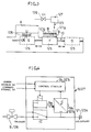
- Fig. 1 is a partial sectional view of a parts feed cassette
- Fig. 14 is a perspective view of a mounting machine having a parts feed cassette.
- a mounting machine A is designed to mount electronic parts 102 on a printed board 101.
- Parts feed cassettes B are installed on a parts feed table 103 arranged at the side of the mounting machine 1, as many as the number of types of electronic parts 102 required in the mounting machine A.
- This parts feed cassette B holds a required type of electronic parts 101 on every occasion, and moves to a position confronting the mounting machine A.
- the mounting machine A sucks the electronic parts 102 supplied from the parts feed cassette B by a suction nozzle 105 provided in a parts suction head 104, and mounts them on the printed board 101.
- the printed board 101 is put on an XY table 106 movable in two mutually orthogonal X and Y directions, and moves in X and Y directions. On this printed board 101, the electronic parts 102 sucked by the suction nozzle 105 and carried up to the mounting positions are mounted.
- the parts feed cassette B is replenished with parts 102 from a bulk cassette 112 detachably fitted to the rear part of an agitating chamber 111.
- parts are agitated by supply of air, and the parts are sent into a parts feed route 113 next to the agitating chamber 111.
- the parts feed route 113 sends the parts 102 up to a parts feed position 114 by air while arranging in neat order, and the parts 102 are supplied into the mounting machine A.
- the parts feed route 113 is opened upward in the parts feed position, so that the arriving parts 102 may be taken out.
- a shutter 115 is provided.
- the mounting machine A picks up the parts 102 by suction nozzle 105 or the like, by pushing down the lever 117 of the parts feed cassette B by a pusher 116, the shutter 115 is opened, and the parts 102 sent up to the parts feed position are picked up by the suction nozzle 105 or the like.
- the parts 102 are agitated by air in the agitating chamber 111, and sent out into a narrow parts feed route 113, and is arranged in one row in a specific direction.
- the parts feed route 113 is narrow, the sending probability of parts 102 into the parts feed route 113 is low. If this probability is low, it cannot be applied in the recent mounting machine A in which high speed is demanded.
- the parts 102 may not be always sent to the parts feed position at sufficient speed and probability. If parts may be fed at high speed, sending may be insufficient or defective.
- the posture and position of the parts may not be constant due to air sending, and they may not be sucked securely by the suction nozzle or jamming may be caused. Or suction by suction nozzle may be applied up to next component 102 and double suction may occur, and the arrangement of the succeeding parts 102 may be disturbed.
- Certain mounting machines A judge shortage of parts if failing to suck the parts 102 for a specific number of times. Actually, only the arrival of parts is delayed, but it is judged as shortage of parts, and the stopping for replenishing parts and replenishing actions are wasteful, which is a problem. Moreover, the delay in arrival of parts or defects may also occur when the air pressure is insufficient for the type, size or shape of the parts.
- the parts feed cassettes B are arranged in a plurality on a moving table 121 as shown in Fig. 3, move to the production position E confronting the mounting machine A, and supplies necessary parts on every occasion. This is the so-called parts leading action.
- the parts feed route 113 of the parts feed cassette B is, as shown in Fig. 1, extended forward from the agitating chamber 111 in the rear part, and at the leading end, as shown in Fig. 2 (a), the parts feed position 114 is directed at right angle to the longitudinal direction of the parts feed cassette B.
- the parts 102 once sent up to the parts feed position 114 of the parts feed route 113 may be slightly moved back from the parts feed position 114 by the inertia at the time of move of the parts feed cassette B. It may also cause problems of delay in parts feed or defects.
- the invention is intended to solve such problems of the prior art, and it is hence a primary object thereof to present a parts feed apparatus and a parts feed method capable of feeding parts quickly, securely, and stably.
- claim 1 of the invention comprises an agitating chamber for agitating parts by air, a parts feed route connected to the agitating chamber for receiving agitated parts in specific direction, arranging them in neat order, and sending up to a specific parts feed position by air, air supply means for supplying air to the agitating chamber and parts feed route, and control means for controlling the air supply means so that the air may be supplied before and after the position for taking out the parts sent up to the parts feed position.
- This constitution enhances the probability of sending out parts to the parts feed route by agitation of parts by increasing the number of times of air feed, and the probability of arrival of parts at parts feed position of the parts sent out to the parts feed route. Still more, the parts at the time of taking out the parts, by the air feed just before taking out the parts, the parts in the parts feed route can be securely and accurately sent out to the parts feed position, and can be immediately taking out directly in the specified direction and position by the suction nozzle or the like. Hence, the parts can be supplied more rapidly and stably than in the prior art.
- the air passage into the agitating chamber opens to the bottom of the agitating chamber, and there is also an auxiliary passage opened backward in the upper part of the front wall portion of the agitating chamber, said front wall portion being formed with an opening of the parts feed route.
- the parts in the agitating chamber are agitated same as in the prior art by the air blowing up obliquely backward from the air passage opened in the bottom.
- the air blowing out from the auxiliary passage above the front wall portion the parts remaining stagnant in the upper space of the front wall portion are sufficiently agitated and diffused, and hence the probability of sending out the parts in specified direction into the parts feed route is enhanced, and it is also effective to avoid staying of parts in this space area to impede sending of parts to the parts feed route or jamming thereof.
- the parts can be supplied more quickly and stably than in the prior art.
- the bottom of the parts feed position opened upward at the leading end of the parts feed route is formed higher than the bottom of the parts feed route at its downstream side.
- the component sent up to the parts feed position is supported higher than the parts at the downstream side of the parts feed route, and by the height difference with the subsequent parts succeeding at the downstream side, only the component at the parts feed position can be easily taken out by the suction nozzle or the like.
- taking-out or suction of parts by suction nozzle may not have effects on the subsequent parts. Accordingly, multiple parts are sent out sequentially, promptly and securely to the parts feed position in a state to be easily taken out, and stably supplied into the mounting machine.
- a slope is provided between the bottom of the parts feed position and the bottom of the parts feed route at its downstream side.
- the parts By the slope of the constitution, the parts may be moved smoothly from the low bottom before the parts feed position of the parts feed route to the high bottom at the parts feed position, so that troubles due to step difference may not occur.
- a magnet is provided in the bottom of the parts feed position opened upward at the leading end of the parts feed route.
- the magnet of the constitution magnetically attracts the magnetic parts sent up to the parts feed position, and holds in position, and therefore the parts sent up to the parts feed position may be held fixed in an adequate position or posture due to effects of air feed, vibration, or taking out or suction of preceding parts. Hence, the parts may be supplied quickly and stably.
- an air groove of narrower width than the passage width of the parts feed route is formed in the central position in the longitudinal direction of at least one of the bottom and top of the parts feed route, said air groove extending through the parts feed route.
- Claim 7 of the invention is intended to simplify the air supply structure for blowing out air into parts, and the air supply means is branched from the common basic passage into the agitating chamber side air passage for supplying air into the agitating chamber, and the parts feed route side air passage for supplying air into the parts feed route within the main body of the apparatus, whereby air is supplied into the respective agitating chamber and parts feed route.
- the piping structure necessary for supplying air into plural parts can be easily formed by making use of holes and grooves formed in parts of the apparatus main body by drilling or cutting, and the cost can be reduced.
- Claim 8 of the invention in order to branch and supply air to parts appropriately, further comprises adjusting means for adjusting the branching amount of air from the basic passage to the agitating chamber side air passage and parts feed route side air passage.
- the air branching amount from the basic passage to the agitating room side air passage and parts feed route side air passage can be adjusted by the adjusting means, and air supply to parts can be adjusted to an optimum state individually by the branch structure.
- Claim 9 of the invention relating to any one of claims 1 to 8 of the invention, is intended to eliminate unexpected projection of parts at the parts feed position or change in posture or position, and comprises a shutter for opening and closing the upper opening part of the parts feed position in the parts feed route, wherein the shutter is closed at least when supplying air except for the time of taking out the parts.
- the shutter is closed at least when supplying air except for the time of taking out the parts, it is effective to prevent projection of parts arriving at the parts feed position, or change of posture or position.
- the shutter is effective in the constitution in which an air groove is formed in the parts feed route and therefor air has a strong effect on the parts. In such a case, the shutter is useful for feeding the parts quickly and stably.
- the agitating chamber and parts feed route are formed of ceramic members detachably fitted to the apparatus main body.
- the agitating chamber and parts feed route of ceramic members, the agitating chamber and parts feed route are hardly worn, although frequently contacting with the parts, and quick and stable feed of parts can be guaranteed for a long period. Moreover, since only the necessary portions may be made of ceramic members which are detachable from the main body and therefor exchangeable, it is possible to prevent undue increase in manufacturing cost.
- the ceramic members are divided into plural members.
- the ceramic members are divided into plural members, when the agitating chamber and parts feed route are complicated in shape or large in size, they can be formed partially, easily and inexpensively, and if broken and necessary to replace parts, they can be only partially replaced, and hence the running cost may be reduced.
- Claim 12 of the invention relates to a parts feed method using a parts feed cassette for sending out part to the parts feed route while agitating by air, and further sending up to the parts feed position in the parts feed route while aligning the parts in neat order, wherein prior to start of feed of parts when feeding parts from the parts feed cassette to the mounting machine, air is preliminarily supplied to the parts feed cassette to align the parts in neat order to send tip to the parts feed position in the parts feed route beforehand.
- the parts can be sent up to the parts feed position in the parts feed route beforehand, while the succeeding parts can be put in neat order.
- parts feed is started and air is supplied for parts feed , so that the part can be supplied quickly, securely and stably.
- preliminary supply of air is effected as required depending on the parts feed cassette selected for use among plural cassettes.
- Claim 14 of the invention is intended to preliminarily supply air in the midway of the movement of the parts feed cassette from a waiting position to a working position where the mounting machine works.
- air can be supplied preliminarily without taking extra time for the cycle of the parts feed at the working position, and by necessary and sufficient preliminary supply of air, the parts can be securely sent up to the parts feed position in the parts feed route in any case, while the succeeding parts can be securely arranged in neat order. Therefore, it is effective for supplying air preliminarily to all of plural parts feed cassettes by changeover of production types of parts.
- the parts feed cassette moves to the working position and the parts in the parts feed cassette return back by inertia, or parts are not sent up to the parts feed position due to fluctuations of the parts feed function by air supply, or in other cases of defective feed of parts
- the parts can be securely sent preliminarily to the parts feed position.
- the succeeding parts can be securely put in neat order, and arrival failure of parts at the time of parts feed can be prevented.
- Claim 16 of the invention comprises a parts feed cassette for sending out parts to a parts feed route while agitating by air, and sending up to a parts feed position of the parts feed route while arranging them in neat order to feed up to a mounting machine, a moving table for picking up the parts feed cassette at waiting position and moving up to the working position by the mounting machine, a drive mechanism for moving this moving table, air supply means for supplying air to the parts feed cassette on the moving table at the working position, preliminary air supply means for supplying air to the parts feed cassette on the moving table at an intermediate position between the waiting position and working position, and control means for operating the air supply means and preliminary air supply means appropriately.
- the parts feed cassette is put on the moving table at the waiting position, and when it is moved to the working position by the mounting machine, the control means actuates the air supply means, and air is supplied to the parts feed cassette at the parts feed position confronting the mounting machine. Therefore, the parts can be sent up to the parts feed position of the parts feed route same as in the prior art, and also the succeeding parts can be arranged in neat order, and the parts sent up to the parts feed position can be fed to the mounting machine.
- control means actuates the preliminary air supply means, so that the air can be preliminarily supplied to the parts feed cassette, so that the parts feed method of claim 14 can be achieved automatically.
- control means can actuate the air supply means as required preliminarily prior to start of feed of parts at the working position, so that the parts feed method of claim 15 of the invention may be achieved automatically.
- Claim 17 of the invention also comprises air pressure adjusting means for adjusting the air pressure in the air supply route from the air supply source.
- a parts feed cassette B comprises, as shown in Fig. 1 (a) and Fig. 2 (a), an agitating chamber 111 for agitating parts 102 by air 1a, and a parts feed route 113 extending forward from the agitating chamber 111 for receiving those in specified direction out of the agitated parts 102 and sending up to a parts feed position 114 by air 1b.
- the parts feed cassette B is connected to air supply means 4 at production position E by a mounting machine A, and air 1a and 1b are blown out to the agitating chamber 111 and parts feed route 113.
- the parts 102 are agitated by the air 1a in the agitating chamber 111, the parts 102 in specified direction are sent out into the parts feed route 113, and are sent up to the parts feed position 114 by air 1b.
- the parts 102 are picked up by a suction nozzle 105, and carried forward and mounted on a printed board 101.
- the agitating chamber 111 is connected so that a bulk cassette 112 can be attached and detached as shown, for example, in Fig. 1 (a) or Fig. 2 (a), and is replenished with parts 102.
- an opening 112a of the bulk cassette 112 is fitted so as to be detached and attached from above in a dovetail groove 119 formed in a rear part of the agitating chamber 111 of a cassette main body 118.
- the opening of the bulk cassette 112 and the agitating chamber 111 communicate with each other.
- the shape of the agitating chamber is not particularly defined, but the agitating chamber of the embodiment is formed so that the size becomes smaller in several steps sequentially from the rear side to which the bulk cassette 112 is connected toward the forward side linking with the parts feed route 113.
- the agitated parts 102 become smaller in quantity in the process of moving from the large rear agitating chamber 111a to the smallest agitating chamber 111c through an intermediate agitating chamber 111b, and are smoothly sent out to the parts feed route 113 from the smallest agitating chamber 111c.
- the air passage 121a to the agitating chamber 111 is provided so that the air 1a may be blow up obliquely upward, slightly behind the bottom corresponding to the agitating chambers 111a to 111c.
- the parts 102 in the agitating chamber 111 are agitated same as in the prior art by the air blown up obliquely behind from the air passage 121a opened in the bottom.
- air 1c is blown out from the auxiliary passage 121c opened behind, so that the parts 102 staying still in the front wall portion 111d can be sufficiently agitated and diffused.
- the parts 102 are set in specified direction, and sent out into the parts feed route 113 at an increased probability, while avoiding escape of the parts from the parts feed route 113 or jamming due to staying of the parts 102 in the mentioned area, so that the parts 102 can be supplied more quickly and stably than in the prior art.
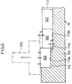
- the bottom 113a of the parts feed position 114 of the parts feed route 113 is set higher than the bottom 113b of the downstream side of the parts feed direction by step S as shown in Fig. 5, and a slope 113c is provided between the bottom 113a of the parts feed position 114 and the downstream side bottom 113b.
- the parts 102 can be smoothly moved from the low bottom 113b before the parts feed position 114 to the high bottom 113a of the parts feed position 114 by the slope 113c, so that trouble may not be caused by the step S.
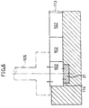
- a magnet 21 is attached to the bottom 3a of the parts feed position 114.
- the magnet 21 holds the position by attracting magnetic parts 102 sent to the parts feed position 114.
- the parts 102 sent up to the parts feed position 114 are not deviated from the proper position or posture due to effects of supply of air, vibration, or taking-out action or suction of preceding parts 102, so that it is helpful for presenting the parts 102 quickly and stably.
- the magnet 21 in Fig. 6 and step S in Fig. 4 are combined, the both actions and effects are obtained simultaneously, which is more preferable.
- an air groove 113e is formed from the front wall portion 111d to the parts feed position 114, in a smaller width than the passage width of the parts feed route 113 as shown in Fig. 2 so that parts 102 may not get in.
- the air groove 113e when the air groove 113e is formed in at least one of the bottom 113a and top 113d of the parts feed route 113, the air 1b passes through up to the parts feed position 114, and gets into the parts feed route 113 from the groove 113e, so that the parts 102 may be sent up to the parts feed position 114.
- the parts 102 in the parts feed route 113 smoothly move up to the parts feed position 114.
- the air groove 113e is helpful for sending the parts 102 securely into the parts feed position 114 and feeding the parts 102 quickly and stably. It is more effective when the air groove 113e is formed in both bottom 113a and top 113d.
- the basic passage 121 of the air supply means 4 is branched within the cassette main body 118 into the agitating chamber side air passage 121a and auxiliary passage 121c for supplying air 1a, 1c into the agitating chamber 111, and the parts feed route side air passage 121b for supplying air 1b into the parts feed route 113, and air is supplied into the agitating chamber 111 and parts feed route 113.
- the piping structure necessary for supplying air 1a to 1c to plural sections is easily formed by drilling holes or cutting grooves in the cassette main body 118, and hence the cost can be reduced. when forming the grooves, by covering the grooves with seal member, an enclosed passage can be formed.
- a conventional shutter 115 is provided as shown in Fig. 1 (a) and Fig. 2 (a), and the upper opening is designed to be opened and closed.
- This shutter 115 is controlled by a control device 122 so that it may be closed at least when supplying air, except for the period of taking out the parts, in particular.
- the shutter 115 prevents unexpected projection of parts 102 except when taking out the parts, or changes of posture or position. That is, the shutter 115 prevents projection of parts 102 sent up to the parts feed position 114 by supplied air or changes in posture or position, especially when supplying air. As the air groove 113e is formed, and air has strong effects on the parts 102, the shutter 115 sufficiently copes with unexpected events, and help feed the parts 102 quickly and stably.
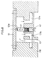
- the agitating chamber 111 and parts feed route 113 are fitted detachably to the cassette main body 118 by screw 33 and cover 34 as shown in Fig. 1 (a) and Fig. 7.
- the agitating chamber 111 and parts feed route 113 are fabricated of ceramic members 32, and are hardly worn, although contacting frequently with the parts 102, so that quick and stable feed of parts 102 may be guaranteed for a long period. Since the ceramic members 32 are detachably fitted to the cassette main body 118, only necessary portions may be made of ceramics, and fitted exchangeably, so that rise of manufacturing cost may be suppressed.
- the ceramics 32 are divided into plural members, more specifically, into three sections, the agitating chamber section 32a, upstream side chute section 32b, and downstream side chute section 32c, and fixed by screws.
- the ceramics 32 when complicated in shape, can be formed easily and inexpensively, and if broken, the sections can be replaced partially, so that the running cost may be reduced.
- Such parts feed apparatus for feeding parts to the mounting machine A by using the parts feed cassette B is structured as shown in Fig. 3. That is, the parts feed apparatus comprises a moving table 101 for moving between waiting position D for picking up the parts feed cassette B and production position E as working position by the objective mounting machine A, and a drive mechanism 100 composed of a screw shaft, servo motor having a rotary shaft to be engaged therewith, and others, for moving the moving table 101.
- the air supply means 4 is provided at the production position E, and connected to an air supply port 121g at the production position E confronting the machine A, out of plural parts feed cassettes B on the moving table 101 located at this position, so that air may be supplied into the parts feed cassette B.
- the drive mechanism 100 moves the moving table 101 between the waiting position D and production position E. Moreover, the drive mechanism 100 moves a specific one of the parts feed cassettes B on the moving table 101 at the production position E so as to confront the mounting machine A. The drive mechanism 100 also moves the moving table 101 at the intermediate position F, and moves a specific one of the parts feed cassettes B on the moving table 101 so as to confront the preliminary air supply means 123.
- the moving table 101 picks up a necessary number of parts feed cassettes B at the waiting position D, or can replace with a necessary parts feed cassette B, or exchange the bulk cassette 112. Thus, the moving table 101 picks up parts feed cassettes B containing necessary parts, and moves to the production position E.
- this moving table 101 confronts the mounting machine A, air is supplied into the parts feed cassette B at the parts feed position from the air supply means 4.
- the air supplied into the parts feed cassette B sends the parts 102 up to the parts feed position 114 of the parts feed route 113, and arranges the subsequent parts 102 in neat order.
- the mounting machine A picks up the parts 102 supplied by the parts feed cassette B by the suction nozzle 105 provided in the parts mounting head 104, and places on specified positions of an electronic circuit board positioned by the mounting machine A.
- the mounting machine A is not limited to the apparatus for mounting electronic parts on the electronic circuit board. It may be any machine for assembling work or doing various jobs by using parts.
- the parts 102 can be sent up to the parts feed position 114 preliminarily without taking extra time in the job cycle for parts feed, while subsequent parts 102 can be arranged neatly.
- the parts 102 preliminarily sent up to the parts feed position 114 of the parts feed route 113 are securely held at t he parts feed position 114, and the subsequent parts 102 are also maintained in securely arranged state, so that the parts 102 may be fed quickly, securely, and stably.
- Preliminary supply of air is effected as required for the selectively used parts feed cassette B.
- the parts 102 are newly supplemented due to shortage of parts, or the parts 102 are changed due to production type changeover, or feed of parts 102 is unstable, only specific parts feed cassette B may be supplied, so that wasteful preliminary supply of air may be avoided, and quick, secure and stable feed of parts 102 may be achieved.
- preliminary supply of air is achieved without taking extra time for the cycle of parts feed at the production position E.
- the parts 102 can be always sent up to the parts feed position 114 of parts feed route 113, and subsequent part 102 can be securely arranged neatly.
- Preliminary supply of air is useful for preliminary supply of air to all of plural parts feed cassettes B by production type changeover of parts 102.
- preliminary air supply is effected by the air supply means 4 on the parts feed cassette B at the production position E. That is, after the parts feed cassette B has moved to the production position E, before start of feed of parts at the production position E, air is supplied preliminarily. Therefore, if the parts in the parts feed cassette B moving to the production position E are deviated from the parts feed position 114 of the parts feed route 113 by the inertia at the time of move of the parts feed cassette B, or the parts have not arrived yet at the parts feed position due to fluctuation of parts feed function by air, or in other defective feeding cases, the parts 102 can be securely sent preliminarily up to the parts feed position, and subsequent parts 102 may be arranged in neat order. Such preliminary supply of air is effective in the event of arrival failure of parts 102 at the time of parts feed.
- the air supply means 4 and preliminary air supply means 123 supply air from a main compressor 6 as air supply source to the parts feed cassette B through one basic passage 121 in the cassette main body 118 through regulator 7, solenoid valves 8, 126, and air pressure regulators (Electropneumatic High-Reg of SMC) 9, 127 as air pressure regulating means.
- the air pressure regulator 9 stabilizes the air supply pressure and air feed rate as being set for blowing out air 1a, 1b.
- the solenoid valve 126 defines the preliminary supply timing of air and air supply duration by the preliminary air supply means 123.
- the air pressure regulator 127 stabilizes the air pressure and air flow rate for preliminary supply as being set by the preliminary air supply means 123.
- the air pressure supplied from the main compressor 6 fluctuates or varies, it is controlled to a specified value by the air pressure regulator 9, and optimum conditions of air pressure and air flow for parts 102 are maintained, so that the parts 102 may be fed stably.
- the air pressure regulator 9, 127 comprise, as shown in Fig. 4, solenoid valves 9a, 127a positioned somewhere in the air supply ducts from the solenoid valves 8, 126 to the basic passages 121, 123a, sensors 9b, 127b for detecting the pressure of secondary air at the downstream side of solenoid valves 9a, 127a, and control circuits 9c, 127c to which these solenoid valves 9a, 127a and pressure sensors 9b, 127b are connected.
- the control circuits 9c, 127c receive a command signal from the control device 122 and detection signals from the pressure sensors 9b, 127b, and judges if the detection signals from the pressure sensors 9b, 127b are larger than or smaller than the command signal from the control device 122. Moreover, the control circuits 9c, 127c change over the solenoid valves 9a, 127a to the supply side and exhaust side, and hence even if the primary side air pressure fluctuates, the secondary side air pressure is kept constant, thereby controlling so that the pressure and amount of supply air to the parts feed cassette B may be always constant as being set.
- the parts feed cassette B only by controlling supply of air and stop of supply by opening and closing the solenoid valve 8, the parts 102 are supplied to the parts feed position 114 as being set. At this time, parts feed may be stabilized by supply of preliminary air as required. Also by controlling supply of air and stop of supply by opening and closing the solenoid valve 126, in the parts feed cassette B on the moving table 101 at the intermediate position F, by preliminary supply of air as required, the parts can be preliminarily sent up to the parts feed position 114 of the parts feed route 113, and subsequent parts 102 may be arranged, so that parts feed may be stabilized.
- the control device 122 controls so that the parts mounting action by the mounting machine A and the parts feed action by the parts feed cassette B may be mutually synchronized in a period of 0° to 360° as shown in Fig. 1 (b).
- the control device 122 simultaneously controls the solenoid valve 8.
- air supply for the parts feed is effected by opening and closing the solenoid valve 8 at time G and H before and after the parts 102 sent up to the parts feed position 114 are sucked and taken out by the suction nozzle 105, and preliminary air supply is effected as required at point J prior to air supply for parts feed.
- the solenoid valve 126 which is installed, together with the air pressure regulator 127, in the midst of the air supply route to the preliminary air supply means 123 is also controlled to be opened and closed for preliminary air supply on necessary point.
- the parts 102 are taken out securely by the suction nozzle 105 without being affected by the air supply when taking out parts. Still more, by increasing the number of times of supply of air 1a, 1b, when the probability of sending out the parts 102 into the parts feed route 113 by agitation of parts 102 is enhanced, the probability of arrival of parts 102 sent out to the parts feed route 113 in the parts feed position 114 is heightened.
- the parts in the parts feed route 113 can be securely and accurately sent up to the parts feed position 114.
- the parts 102 are taken out in proper posture and position by the suction nozzle 105 and others, so that the parts 102 may be fed more quickly and stably than before.
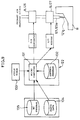
- the control device 122 is composed of, as shown in Fig. 9, a microcomputer 131, and a control program 132 for controlling various functions and operation of devices for mounting parts on electronic circuits.
- the microcomputer 131 always receives a cycle signal from a cycle timer 133 for controlling the operation cycle of the mounting machine A, and synchronizes the controls on the basis thereof.
- the cycle timer 133 is an absolute encoder for outputting the phase of a head shaft 124a of a parts mounting head 124 in the mounting machine A.
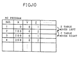
- the microcomputer 131 receives the moving information of the moving table 101, and parts information such as type, shape, and size of the parts 102 to be fed, from parts data 134 relating to various parts 102 stored in the operation program of the mounting machine A, and data from the NC program 135 as the data of operation control, and controls the solenoid valves 8, 126, and air pressure regulators 9, 127, and sets optimally the timing and duration of air supply for parts feed and prior preliminary air supply, and also sets the air pressure of air supply optimally.
- the NC program 135 is, for example, as shown in Fig.
- Fig. 11 to Fig. 13 are flowcharts showing practical examples of the above control.
- the moving table 101 is the Z table.
- Fig. 11 shows a practical example of so-called parts leading action by supplying air preliminarily from the preliminary air supply means 123 and positioning the parts 102 at the parts feed position of the parts feed route 113.
- parts leading action is set on all parts feed cassettes B on the moving table 101.
- Each parts feed cassette B is provided with Z number, and requirement of parts leading action and finished state are controlled by the Z number.
- parts leading action is effected on all parts, all Z numbers are specified.
- the Z number is specified for the parts feed cassette B with shortage of parts.
- parts leading action is effected.
- the Z numbers of parts feed cassettes B on the Z table are sequentially read out at intermediate position F, and it is judged if the parts feed cassette B requires parts leading action or not, and only the required parts feed cassette B, on every occasion, is moved to the position confronting the preliminary air supply means 123, and parts leading action is effected.
- Fig. 12 shows a practical example of parts leading action before start of parts feed by each parts feed cassette B on the Z table at the production position E.
- the parts feed cassette B of the Z number used in parts feed is moved to the parts feed position confronting the mounting machine A.
- air is supplied to feed parts by the air supply means 4, and parts are fed by the parts feed cassette B at the parts feed position. Successively, by mounting parts by the mounting machine A, the above operation is repeated when continuing production, and production is terminated if necessary.
- Fig. 13 shows a practical example of control for setting the air supply timing, duration and pressure.
- the program is progressed in the condition that the parts feed cassette B is bulk cassette, and first the shape of parts is judged. In the case of square chip parts or in the case of cylindrical parts, the air supply timing, duration, and pressure are set individually depending on the parts size.
- the predetermined timing, duration and pressure are adjusted depending on the moving direction and moving distance.
Priority Applications (1)
| Application Number | Priority Date | Filing Date | Title |
|---|---|---|---|
| EP99115268A EP0951210B1 (de) | 1995-08-21 | 1996-08-20 | Vorrichtung zum Zuführen von Bauteilen |
Applications Claiming Priority (6)
| Application Number | Priority Date | Filing Date | Title |
|---|---|---|---|
| JP212088/95 | 1995-08-21 | ||
| JP21208895A JP3461629B2 (ja) | 1995-08-21 | 1995-08-21 | 部品供給装置 |
| JP21208895 | 1995-08-21 | ||
| JP286967/95 | 1995-11-06 | ||
| JP28696795 | 1995-11-06 | ||
| JP7286967A JPH09130087A (ja) | 1995-11-06 | 1995-11-06 | 部品供給方法およびその装置 |
Related Child Applications (1)
| Application Number | Title | Priority Date | Filing Date |
|---|---|---|---|
| EP99115268A Division EP0951210B1 (de) | 1995-08-21 | 1996-08-20 | Vorrichtung zum Zuführen von Bauteilen |
Publications (2)
| Publication Number | Publication Date |
|---|---|
| EP0762823A1 true EP0762823A1 (de) | 1997-03-12 |
| EP0762823B1 EP0762823B1 (de) | 2000-11-08 |
Family
ID=26518992
Family Applications (2)
| Application Number | Title | Priority Date | Filing Date |
|---|---|---|---|
| EP99115268A Expired - Lifetime EP0951210B1 (de) | 1995-08-21 | 1996-08-20 | Vorrichtung zum Zuführen von Bauteilen |
| EP96113337A Expired - Lifetime EP0762823B1 (de) | 1995-08-21 | 1996-08-20 | Vorrichtung zum Zuführen von Bauteilen und Verfahren zum Zuführen von Bauteilen |
Family Applications Before (1)
| Application Number | Title | Priority Date | Filing Date |
|---|---|---|---|
| EP99115268A Expired - Lifetime EP0951210B1 (de) | 1995-08-21 | 1996-08-20 | Vorrichtung zum Zuführen von Bauteilen |
Country Status (3)
| Country | Link |
|---|---|
| US (1) | US5853108A (de) |
| EP (2) | EP0951210B1 (de) |
| DE (2) | DE69610889T2 (de) |
Families Citing this family (14)
| Publication number | Priority date | Publication date | Assignee | Title |
|---|---|---|---|---|
| KR100279368B1 (ko) * | 1996-11-15 | 2001-01-15 | 가와다 미쓰구 | 칩부품공급장치및이에사용되는흡착플레이트 |
| JPH1159899A (ja) * | 1997-08-20 | 1999-03-02 | Mitsui High Tec Inc | 球状物の供給装置 |
| US6041964A (en) * | 1997-10-02 | 2000-03-28 | Universal Instruments Corporation | Method and apparatus for supplying components |
| JP3579234B2 (ja) * | 1997-12-09 | 2004-10-20 | 太陽誘電株式会社 | チップ部品供給装置 |
| JPH11220290A (ja) * | 1998-02-03 | 1999-08-10 | Taiyo Yuden Co Ltd | チップ部品取込装置 |
| US6575347B2 (en) | 2000-06-17 | 2003-06-10 | Textron Inc. | Rivet feed slider |
| FR2845978B1 (fr) * | 2002-10-21 | 2005-07-22 | F2 C2 System | Dispositif de distribution de pieces, notamment de rivets, delivrees en sortie d'un moyen de stockage tel un bol vibrant, son procede de travail et bol vibrant adapte |
| NL1029098C2 (nl) * | 2005-05-23 | 2006-11-27 | Assembleon Nv | Werkwijze voor het toevoeren van een component alsmede componenttoevoerinrichting. |
| JP4525514B2 (ja) * | 2005-08-01 | 2010-08-18 | パナソニック株式会社 | バルクフィーダおよび電子部品実装装置 |
| CN104724481B (zh) * | 2013-12-20 | 2017-07-18 | 深圳富泰宏精密工业有限公司 | 筛选机构 |
| US10087016B2 (en) * | 2015-03-06 | 2018-10-02 | Kurashiki Boseki Kabushiki Kaisha | Article supply device |
| JP6520441B2 (ja) * | 2015-06-16 | 2019-05-29 | 株式会社村田製作所 | 電子部品搬送装置及びテーピング電子部品連の製造方法 |
| DE102015113995A1 (de) * | 2015-08-24 | 2017-03-02 | Osram Opto Semiconductors Gmbh | Verfahren zum Abholen eines elektronischen Bauteils zur Bestückung und Abholeinrichtung zum Abholen eines elektronischen Bauteils zur Bestückung |
| NL2021777B1 (en) * | 2018-10-08 | 2020-05-12 | Urban Mining Corp Bv | Separation apparatus and method |
Citations (3)
| Publication number | Priority date | Publication date | Assignee | Title |
|---|---|---|---|---|
| CH482610A (fr) * | 1967-10-25 | 1969-12-15 | Lecureux Bernard | Procédé et dispositif de transport pneumatique de pièces |
| DE3717918A1 (de) * | 1986-05-27 | 1987-12-03 | Nitto Kogyo Kk | Vorrichtung zum trennen und ausrichten von chips |
| EP0452038A1 (de) * | 1990-04-07 | 1991-10-16 | Murata Manufacturing Co., Ltd. | Vorrichtung zum Ausrichten von elektronischen Chipbauteilen |
Family Cites Families (8)
| Publication number | Priority date | Publication date | Assignee | Title |
|---|---|---|---|---|
| US2384738A (en) * | 1943-08-05 | 1945-09-11 | Thomas H Speller | Rivet magazine |
| US4401234A (en) * | 1981-06-01 | 1983-08-30 | Universal Research Laboratories, Incorporated | Apparatus for applying integrated circuits to a circuit board |
| JPS6063523U (ja) * | 1983-10-04 | 1985-05-04 | 日本ノーシヨン工業株式会社 | 釦加工装置の部品供給装置 |
| US5143253A (en) * | 1988-09-02 | 1992-09-01 | Tdk Corporation | Chip packaging means and supply mechanism for supplying chips by using the chip packaging means |
| JPH0730572Y2 (ja) * | 1990-05-31 | 1995-07-12 | 太陽誘電株式会社 | 電子部品供給装置 |
| JP3081400B2 (ja) * | 1993-01-18 | 2000-08-28 | 三洋電機株式会社 | 電子部品自動装着装置 |
| JP3040285B2 (ja) * | 1993-09-17 | 2000-05-15 | 松下電器産業株式会社 | 部品供給ユニット |
| JPH07212084A (ja) * | 1994-01-24 | 1995-08-11 | Matsushita Electric Ind Co Ltd | 部品供給装置 |
-
1996
- 1996-08-16 US US08/698,736 patent/US5853108A/en not_active Expired - Fee Related
- 1996-08-20 DE DE69610889T patent/DE69610889T2/de not_active Expired - Fee Related
- 1996-08-20 EP EP99115268A patent/EP0951210B1/de not_active Expired - Lifetime
- 1996-08-20 EP EP96113337A patent/EP0762823B1/de not_active Expired - Lifetime
- 1996-08-20 DE DE69637549T patent/DE69637549D1/de not_active Expired - Fee Related
Patent Citations (3)
| Publication number | Priority date | Publication date | Assignee | Title |
|---|---|---|---|---|
| CH482610A (fr) * | 1967-10-25 | 1969-12-15 | Lecureux Bernard | Procédé et dispositif de transport pneumatique de pièces |
| DE3717918A1 (de) * | 1986-05-27 | 1987-12-03 | Nitto Kogyo Kk | Vorrichtung zum trennen und ausrichten von chips |
| EP0452038A1 (de) * | 1990-04-07 | 1991-10-16 | Murata Manufacturing Co., Ltd. | Vorrichtung zum Ausrichten von elektronischen Chipbauteilen |
Also Published As
| Publication number | Publication date |
|---|---|
| EP0762823B1 (de) | 2000-11-08 |
| DE69637549D1 (de) | 2008-07-10 |
| DE69610889T2 (de) | 2001-03-01 |
| EP0951210A3 (de) | 1999-10-27 |
| EP0951210A2 (de) | 1999-10-20 |
| EP0951210B1 (de) | 2008-05-28 |
| DE69610889D1 (de) | 2000-12-14 |
| US5853108A (en) | 1998-12-29 |
Similar Documents
| Publication | Publication Date | Title |
|---|---|---|
| US5853108A (en) | Parts feed apparatus and parts feed method | |
| US7356919B2 (en) | Component mounting method | |
| EP3026995B1 (de) | Komponentenübertragungsvorrichtung für eine komponentenmontagemaschine | |
| EP0904678B1 (de) | Verfahren und einrichtung zur montage von bauteilen | |
| US6918176B2 (en) | Mounting apparatus of electronic parts and mounting methods of the same | |
| US20040130863A1 (en) | Method and apparatus for mounting electronic components and program therefor | |
| KR20000047969A (ko) | 전자부품 설치장치 및 설치방법 | |
| JP2007048891A (ja) | 表面実装機 | |
| US6807727B2 (en) | Manufacturing and carrier system with feeder/programming/buffer system | |
| WO2015198437A1 (ja) | テープフィーダ | |
| US6532395B1 (en) | Manufacturing system with feeder/programming/buffer system | |
| US6152283A (en) | Circuit-component supplying method and circuit-component feeder | |
| US7100278B2 (en) | Component mounting apparatus and method | |
| JPH09130087A (ja) | 部品供給方法およびその装置 | |
| US6189207B1 (en) | Method of mounting parts | |
| JP2020074472A (ja) | マルチフィーダ装置 | |
| JP7393845B2 (ja) | 基板生産システム | |
| JP6661460B2 (ja) | 部品供給装置、部品供給方法および表面実装機 | |
| JPH10200293A (ja) | 部品供給装置 | |
| JPH104294A (ja) | 電子部品挿入装置 | |
| JPH0964590A (ja) | 部品供給装置 | |
| JP2969955B2 (ja) | 部品実装方法 | |
| JP3028636B2 (ja) | 部品実装方法および部品実装機 | |
| JP6735637B2 (ja) | 部品種割り振り方法および部品種割り振り装置 | |
| EP3592126A1 (de) | Komponententransfervorrichtung |
Legal Events
| Date | Code | Title | Description |
|---|---|---|---|
| PUAI | Public reference made under article 153(3) epc to a published international application that has entered the european phase |
Free format text: ORIGINAL CODE: 0009012 |
|
| AK | Designated contracting states |
Kind code of ref document: A1 Designated state(s): DE FR GB IT |
|
| 17P | Request for examination filed |
Effective date: 19970130 |
|
| 17Q | First examination report despatched |
Effective date: 19971015 |
|
| GRAG | Despatch of communication of intention to grant |
Free format text: ORIGINAL CODE: EPIDOS AGRA |
|
| 17Q | First examination report despatched |
Effective date: 19971015 |
|
| GRAG | Despatch of communication of intention to grant |
Free format text: ORIGINAL CODE: EPIDOS AGRA |
|
| GRAH | Despatch of communication of intention to grant a patent |
Free format text: ORIGINAL CODE: EPIDOS IGRA |
|
| GRAH | Despatch of communication of intention to grant a patent |
Free format text: ORIGINAL CODE: EPIDOS IGRA |
|
| GRAA | (expected) grant |
Free format text: ORIGINAL CODE: 0009210 |
|
| AK | Designated contracting states |
Kind code of ref document: B1 Designated state(s): DE FR GB IT |
|
| REF | Corresponds to: |
Ref document number: 69610889 Country of ref document: DE Date of ref document: 20001214 |
|
| ITF | It: translation for a ep patent filed |
Owner name: SOCIETA' ITALIANA BREVETTI S.P.A. |
|
| ET | Fr: translation filed | ||
| PLBE | No opposition filed within time limit |
Free format text: ORIGINAL CODE: 0009261 |
|
| STAA | Information on the status of an ep patent application or granted ep patent |
Free format text: STATUS: NO OPPOSITION FILED WITHIN TIME LIMIT |
|
| 26N | No opposition filed | ||
| REG | Reference to a national code |
Ref country code: GB Ref legal event code: IF02 |
|
| PGFP | Annual fee paid to national office [announced via postgrant information from national office to epo] |
Ref country code: FR Payment date: 20060808 Year of fee payment: 11 |
|
| PGFP | Annual fee paid to national office [announced via postgrant information from national office to epo] |
Ref country code: GB Payment date: 20060816 Year of fee payment: 11 |
|
| PGFP | Annual fee paid to national office [announced via postgrant information from national office to epo] |
Ref country code: IT Payment date: 20060831 Year of fee payment: 11 |
|
| GBPC | Gb: european patent ceased through non-payment of renewal fee |
Effective date: 20070820 |
|
| REG | Reference to a national code |
Ref country code: FR Ref legal event code: ST Effective date: 20080430 |
|
| PG25 | Lapsed in a contracting state [announced via postgrant information from national office to epo] |
Ref country code: FR Free format text: LAPSE BECAUSE OF NON-PAYMENT OF DUE FEES Effective date: 20070831 |
|
| PGFP | Annual fee paid to national office [announced via postgrant information from national office to epo] |
Ref country code: DE Payment date: 20080905 Year of fee payment: 13 |
|
| PG25 | Lapsed in a contracting state [announced via postgrant information from national office to epo] |
Ref country code: GB Free format text: LAPSE BECAUSE OF NON-PAYMENT OF DUE FEES Effective date: 20070820 |
|
| PG25 | Lapsed in a contracting state [announced via postgrant information from national office to epo] |
Ref country code: IT Free format text: LAPSE BECAUSE OF NON-PAYMENT OF DUE FEES Effective date: 20070820 |
|
| PG25 | Lapsed in a contracting state [announced via postgrant information from national office to epo] |
Ref country code: DE Free format text: LAPSE BECAUSE OF NON-PAYMENT OF DUE FEES Effective date: 20100302 |