EP0762012A1 - Amortisseur dynamique - Google Patents
Amortisseur dynamique Download PDFInfo
- Publication number
- EP0762012A1 EP0762012A1 EP96111100A EP96111100A EP0762012A1 EP 0762012 A1 EP0762012 A1 EP 0762012A1 EP 96111100 A EP96111100 A EP 96111100A EP 96111100 A EP96111100 A EP 96111100A EP 0762012 A1 EP0762012 A1 EP 0762012A1
- Authority
- EP
- European Patent Office
- Prior art keywords
- vibration damper
- flywheel
- loop
- damper according
- plate
- Prior art date
- Legal status (The legal status is an assumption and is not a legal conclusion. Google has not performed a legal analysis and makes no representation as to the accuracy of the status listed.)
- Granted
Links
- 229920001971 elastomer Polymers 0.000 claims description 10
- 230000010355 oscillation Effects 0.000 claims description 5
- 230000006378 damage Effects 0.000 claims description 4
- 239000000463 material Substances 0.000 claims description 3
- 238000004804 winding Methods 0.000 claims description 3
- 239000006096 absorbing agent Substances 0.000 description 2
- 230000003584 silencer Effects 0.000 description 2
- 229910000831 Steel Inorganic materials 0.000 description 1
- 230000001154 acute effect Effects 0.000 description 1
- 238000005452 bending Methods 0.000 description 1
- 230000005540 biological transmission Effects 0.000 description 1
- 238000005266 casting Methods 0.000 description 1
- 239000000806 elastomer Substances 0.000 description 1
- 238000007786 electrostatic charging Methods 0.000 description 1
- 238000001125 extrusion Methods 0.000 description 1
- 238000011065 in-situ storage Methods 0.000 description 1
- 238000003780 insertion Methods 0.000 description 1
- 230000037431 insertion Effects 0.000 description 1
- 238000004519 manufacturing process Methods 0.000 description 1
- 239000002184 metal Substances 0.000 description 1
- 230000007935 neutral effect Effects 0.000 description 1
- 239000004033 plastic Substances 0.000 description 1
- 230000002028 premature Effects 0.000 description 1
- 238000004080 punching Methods 0.000 description 1
- 239000007787 solid Substances 0.000 description 1
- 239000010959 steel Substances 0.000 description 1
- 239000000725 suspension Substances 0.000 description 1
- 238000004073 vulcanization Methods 0.000 description 1
Images


Classifications
-
- F—MECHANICAL ENGINEERING; LIGHTING; HEATING; WEAPONS; BLASTING
- F16—ENGINEERING ELEMENTS AND UNITS; GENERAL MEASURES FOR PRODUCING AND MAINTAINING EFFECTIVE FUNCTIONING OF MACHINES OR INSTALLATIONS; THERMAL INSULATION IN GENERAL
- F16F—SPRINGS; SHOCK-ABSORBERS; MEANS FOR DAMPING VIBRATION
- F16F7/00—Vibration-dampers; Shock-absorbers
- F16F7/10—Vibration-dampers; Shock-absorbers using inertia effect
- F16F7/104—Vibration-dampers; Shock-absorbers using inertia effect the inertia member being resiliently mounted
- F16F7/108—Vibration-dampers; Shock-absorbers using inertia effect the inertia member being resiliently mounted on plastics springs
-
- F—MECHANICAL ENGINEERING; LIGHTING; HEATING; WEAPONS; BLASTING
- F16—ENGINEERING ELEMENTS AND UNITS; GENERAL MEASURES FOR PRODUCING AND MAINTAINING EFFECTIVE FUNCTIONING OF MACHINES OR INSTALLATIONS; THERMAL INSULATION IN GENERAL
- F16F—SPRINGS; SHOCK-ABSORBERS; MEANS FOR DAMPING VIBRATION
- F16F1/00—Springs
- F16F1/36—Springs made of rubber or other material having high internal friction, e.g. thermoplastic elastomers
- F16F1/371—Springs made of rubber or other material having high internal friction, e.g. thermoplastic elastomers characterised by inserts or auxiliary extension or exterior elements, e.g. for rigidification
-
- F—MECHANICAL ENGINEERING; LIGHTING; HEATING; WEAPONS; BLASTING
- F16—ENGINEERING ELEMENTS AND UNITS; GENERAL MEASURES FOR PRODUCING AND MAINTAINING EFFECTIVE FUNCTIONING OF MACHINES OR INSTALLATIONS; THERMAL INSULATION IN GENERAL
- F16F—SPRINGS; SHOCK-ABSORBERS; MEANS FOR DAMPING VIBRATION
- F16F3/00—Spring units consisting of several springs, e.g. for obtaining a desired spring characteristic
- F16F3/08—Spring units consisting of several springs, e.g. for obtaining a desired spring characteristic with springs made of a material having high internal friction, e.g. rubber
- F16F3/10—Spring units consisting of several springs, e.g. for obtaining a desired spring characteristic with springs made of a material having high internal friction, e.g. rubber combined with springs made of steel or other material having low internal friction
- F16F3/12—Spring units consisting of several springs, e.g. for obtaining a desired spring characteristic with springs made of a material having high internal friction, e.g. rubber combined with springs made of steel or other material having low internal friction the steel spring being in contact with the rubber spring
-
- B—PERFORMING OPERATIONS; TRANSPORTING
- B60—VEHICLES IN GENERAL
- B60G—VEHICLE SUSPENSION ARRANGEMENTS
- B60G2202/00—Indexing codes relating to the type of spring, damper or actuator
- B60G2202/10—Type of spring
- B60G2202/14—Plastic spring, e.g. rubber
- B60G2202/143—Plastic spring, e.g. rubber subjected to compression
-
- B—PERFORMING OPERATIONS; TRANSPORTING
- B60—VEHICLES IN GENERAL
- B60G—VEHICLE SUSPENSION ARRANGEMENTS
- B60G2204/00—Indexing codes related to suspensions per se or to auxiliary parts
- B60G2204/10—Mounting of suspension elements
- B60G2204/12—Mounting of springs or dampers
- B60G2204/125—Mounting of rubber type springs
-
- B—PERFORMING OPERATIONS; TRANSPORTING
- B60—VEHICLES IN GENERAL
- B60G—VEHICLE SUSPENSION ARRANGEMENTS
- B60G2204/00—Indexing codes related to suspensions per se or to auxiliary parts
- B60G2204/40—Auxiliary suspension parts; Adjustment of suspensions
- B60G2204/45—Stops limiting travel
- B60G2204/4504—Stops limiting travel using cable or band to prevent extension
Definitions
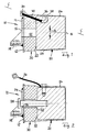
- a support body 10 is composed of a flat plate 12 and an angled bracket 14.
- the plate 12 and the bracket 14 are welded together, for example, and have a common central hole 16;
- the console 14 also has a mounting hole 18 for attaching the support body 10 to a component, not shown, whose vibrations are to be damped in a region projecting at right angles from the plate 12.
- a component can be, for example, an engine block, a transmission housing or an exhaust silencer of a motor vehicle.
- a flywheel mass 20 is connected to the supporting body 10 and has an end face 22 parallel to the plate 12 as well as normal side faces 24.
- the flywheel 20 is usually connected to the supporting body 10 by a safety cable 26 and / or by a safety bolt 28.
- the safety rope 26 is fastened with one of its two ends to one of the side surfaces 24 of the flywheel 20, for example clamped; the other end of the safety cable 26 can, instead of on the support body 10, optionally be fastened to the component whose vibrations are to be damped, for example to an engine block, gearbox or silencer.
- the securing bolt 28 extends through the central hole 16 of the support body 10 and through an elastic intermediate member 30, which also has a hole 32 for this purpose.
- the intermediate member 30 is made of rubber in the example shown, is vulcanized onto the plate 12 of the support body 10 and onto the end face 22 of the flywheel 20 and also extends around it.
- the securing bolt 28 fulfills the additional task of limiting the oscillation amplitude of the flywheel mass 20 and thereby counteracting premature destruction of the elastic intermediate member 30, especially in the case of oscillation resonance.
- Known vibration absorbers of the type shown in FIG. 2 require a considerable manufacturing outlay, since the securing cable 26 and the securing bolt 28 each require at least one hole in the flywheel 20, which can generally only be drilled after the elastic intermediate member 30 has been attached to the Carrier body 10 and vulcanized to the flywheel 20. If such holes were drilled beforehand, then special measures would be required to prevent the holes from becoming blocked, e.g. B. by the fact that during the vulcanization of the intermediate member 30 rubber penetrates into the holes and then they have to be uncovered again.
- the invention is therefore based on the object of securing a vibration damper in a particularly simple but at the same time reliable manner against destruction of the elastic intermediate member and against loss of the flywheel.
- the object is achieved based on a vibration damper of the type described above in that the fuse has at least one ring-shaped, self-contained loop, which is hooked into at least one bracket formed on the supporting body and on the flywheel mass in such a way that it limits the vibration amplitude of the flywheel mass in a main vibration direction parallel to the plate.
- a suspension which is provided in particular for exhaust systems of motor vehicles and has two bushings arranged parallel to one another, one of which is to be fastened to the motor vehicle and the other to a part of the exhaust system.
- the two sockets are connected to each other by a steel flat wire, the ends of which are bent around each of the sockets in such a way that the sockets are held at a predetermined distance from one another.
- the two sockets and the flat wire are embedded in an elastomer that forms an intermediate body between the sockets. This is slim in the area of the socket to be fastened to the motor vehicle and widens towards the other socket, so that the exhaust system fastened to it can oscillate relative to the socket fastened to the motor vehicle.
- the flat wire limits the elasticity of the intermediate body, since it lies in its plane of symmetry, ie in a zone that is neutral with regard to bending stresses, it cannot limit pendulum movements.
- Folding one or more loops according to the invention by at least one bracket each formed on the support body and on the flywheel requires only a small amount of work and can also be automated in suitable cases. With the attachment of the sling or slings, there is no need to wait until the elastic intermediate member has been vulcanized onto the plate and on the flywheel; on the contrary, it is advantageous if the support body, the flywheel and at least one sling are already assembled and then connected to one another by introducing one or more elastic intermediate links to form a compact assembly.
- the loop is preferably a thread or tape winding of a type known in the case of elastic flexible disks (DE-A 2 001 376).
- a thread or tape winding can either be prefabricated or formed in situ by wrapping the brackets formed on the support body and on the flywheel. In both cases it may be appropriate to impregnate the loop formed by a thread or tape wrap with rubber.
- the loop can also be a homogeneous ring made of a material, for example plastic, whose elastic modulus is higher than that of the intermediate link.
- loops according to the invention are particularly suitable if each of them is arranged in a plane that extends obliquely to the main oscillation plane of the flywheel.
- the or each loop can be hooked into the brackets in a figure-eight manner and can thus be held particularly securely.
- a further development of the invention can consist in that at least one loop serving as a fuse forms an electrically conductive connection between the flywheel and the carrier.
- the loop can contain, for example, individual metal threads.
- the or each loop is preferably arranged so that it is at least partially embedded in the elastic intermediate member.
- the brackets can be produced in a particularly simple manner in such a way that, viewed in a plane normal to the plate, they have hook-shaped profiles facing away from one another.
- Such profiles can be produced particularly easily, for example in the case of an essentially plate-shaped support body, by punching, and in many cases, in the case of a solid flywheel, can be produced particularly simply by casting the flywheel together with the holder (s).
- the hanging and fixing of the sling or slings is particularly facilitated if the brackets, viewed in a plane parallel to the plate, have T-shaped profiles.
- the or each holder on the flywheel expediently has a groove machined into it and closed in the direction of the supporting body.
- the vibration damper shown in FIG. 1 corresponds in its details designated by reference numerals 10 to 32 to the known vibration damper described at the beginning with reference to FIG. 2.
- the vibration damper shown in FIG. 1 has a hook-shaped holder 34 and 36 on its support body 10 and on its flywheel mass 20, respectively.
- the bracket 34 on the support body 10 is formed in that the plate 12 is angled in its upper edge region in FIG. 1 in the direction away from the flywheel 20.
- the holder 36 is machined out of the flywheel 20 by a groove 38, for example milled into the flywheel 20, which is closed in the direction of the supporting body 10.
- the two brackets 34 and 36 are connected to one another by a loop-shaped loop 40, which is produced, for example, as a thread or tape wrap, then impregnated with raw rubber or rubber and finally in the manner shown in FIG. 1 on the brackets 34 and 36 has been mounted.
- the elastic intermediate member 30 is only then introduced, for example, that raw rubber is injected into the space between the plate 12 of the support body and the end face 22 of the flywheel 20, the holder 34 and the entire flywheel 20 and the loop 40 being extrusion-coated and the Groove 38 is filled.
- the raw rubber is then vulcanized in the usual way.
- the loop 40 is no longer visible from the outside, since it is completely embedded in rubber. As a result, the loop 40 is fixed in its position and is particularly well protected against damage from external influences.
- Fig. 1 the direction in which the flywheel 20 mainly oscillates is indicated by a double arrow A.
- This main direction of vibration A is parallel to the planes of the plate 12 of the support body 10 and the end face 22 of the flywheel 20.
- the flywheel 20 is in relation to a to the plate 12 and to the end face 22 normal central plane B is designed essentially symmetrical. An exception to this symmetry is made only by the bracket 36 delimited by the groove 38.
- the brackets 34 and 36 are arranged according to FIG. 1 with respect to each other in such a way that the loop 40 lies in a plane C which is with the main direction of vibration A and with Middle plane B includes an acute angle.
- the loop 40 directly limits the vibration amplitude of the flywheel 20 in the main vibration direction A, but only downwards in FIG. 1, whereby the amplitude is also limited indirectly upwards. 1, the angle between A and C is considerably larger than the angle between B and C.
- the vibration damper according to FIG. 3 differs from that shown in FIG. 1 essentially in that both brackets 34 and 36 are arranged in the central plane B and accordingly the loop 40 also lies in the central plane B.
- the hook-shaped brackets 34 and 36 are formed by an expression of the plate 12 or an attachment of the flywheel 20; the plane C of the loop 40 forms an angle with the central plane which differs only slightly from zero.
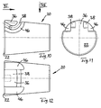
- the vibration absorber according to the invention shown in FIGS. 6 and 7 differ from the previously described embodiments of the invention in that the support body 10 and the flywheel 20 each have two brackets 34 and 36, and accordingly two loops 40, the flywheel 20 with the support body 10 connect. 6 and 7 are both symmetrical with respect to the plane B, which is a common center plane of the support body 10, the flywheel 20 and the elastic intermediate member 30. 6, the two loops 40 cross each other in the central plane B; 7, however, the two loops are arranged converging to the central plane B without reaching it.
- the plate 12 is a completely flat stamped part in the manner of a flange with two fastening holes 42.
- the bracket 34 formed on this plate 12 has a T-shaped profile with two mutually opposite slots 44 for inserting the loop 40.
- the one formed on the flywheel 20 Bracket 36 has a U-shaped groove 38 in the view according to FIG. 12 for inserting the loop 40 and thereby also has a T-shaped profile on the end face 22. In order to facilitate the insertion of the loop 40 into the groove 38, the latter is expanded by lateral recesses 46 which are then filled with the material of the elastic intermediate member 30.
Landscapes
- Engineering & Computer Science (AREA)
- General Engineering & Computer Science (AREA)
- Mechanical Engineering (AREA)
- Vibration Prevention Devices (AREA)
- Percussion Or Vibration Massage (AREA)
Applications Claiming Priority (2)
| Application Number | Priority Date | Filing Date | Title |
|---|---|---|---|
| DE19528560A DE19528560C1 (de) | 1995-08-03 | 1995-08-03 | Schwingungstilger |
| DE19528560 | 1995-08-03 |
Publications (2)
| Publication Number | Publication Date |
|---|---|
| EP0762012A1 true EP0762012A1 (fr) | 1997-03-12 |
| EP0762012B1 EP0762012B1 (fr) | 2000-04-05 |
Family
ID=7768616
Family Applications (1)
| Application Number | Title | Priority Date | Filing Date |
|---|---|---|---|
| EP96111100A Expired - Lifetime EP0762012B1 (fr) | 1995-08-03 | 1996-07-10 | Amortisseur dynamique |
Country Status (4)
| Country | Link |
|---|---|
| EP (1) | EP0762012B1 (fr) |
| DE (2) | DE19528560C1 (fr) |
| ES (1) | ES2143688T3 (fr) |
| PT (1) | PT762012E (fr) |
Cited By (6)
| Publication number | Priority date | Publication date | Assignee | Title |
|---|---|---|---|---|
| EP1059466A1 (fr) * | 1999-06-09 | 2000-12-13 | Hutchinson | Support antivibratoire équipé d'un câble limiteur inextensible |
| EP1574740A1 (fr) * | 2004-03-12 | 2005-09-14 | Hutchinson | Dispositif de liaison antivibratoire |
| WO2014202185A1 (fr) * | 2013-06-21 | 2014-12-24 | Audi Ag | Élément élastique de torsion |
| CN104696409A (zh) * | 2015-02-13 | 2015-06-10 | 柳州金鸿橡塑有限公司 | 质量减振器 |
| DE102004038023B4 (de) * | 2004-08-04 | 2016-09-29 | Vibracoustic Gmbh & Co. Kg | Schwingungstilger |
| DE102016225470A1 (de) * | 2016-12-19 | 2018-06-21 | Volkswagen Aktiengesellschaft | Aggregatlager zum Abstützen einer Antriebskomponente eines Kraftfahrzeuges |
Families Citing this family (1)
| Publication number | Priority date | Publication date | Assignee | Title |
|---|---|---|---|---|
| DE102016213818B4 (de) | 2015-09-03 | 2018-12-13 | Ford Global Technologies, Llc | Fahrzeug mit metallischem Bauteil und Schwingungstilgereinheit |
Citations (6)
| Publication number | Priority date | Publication date | Assignee | Title |
|---|---|---|---|---|
| US1671764A (en) * | 1926-09-07 | 1928-05-29 | Rodic Rubber Co | Spring shackle |
| US1787539A (en) * | 1926-02-16 | 1931-01-06 | Int Motor Co | Cushion connection for vehicle construction |
| FR2340834A1 (fr) * | 1976-02-16 | 1977-09-09 | Renault | Suspension pour bloc-moteurs |
| DE2738965A1 (de) * | 1976-09-02 | 1978-03-09 | Du Pont | Energieaufnahmevorrichtung |
| JPS60109633A (ja) * | 1983-11-16 | 1985-06-15 | Mazda Motor Corp | エンジンの振動減衰装置 |
| DE3834806A1 (de) * | 1987-11-27 | 1989-06-08 | Bbc Brown Boveri & Cie | Daempfungselement und mit diesem daempfungselement stossgedaempftes geraet |
Family Cites Families (3)
| Publication number | Priority date | Publication date | Assignee | Title |
|---|---|---|---|---|
| JPH0315870Y2 (fr) * | 1985-10-18 | 1991-04-05 | ||
| US4817909A (en) * | 1987-12-07 | 1989-04-04 | Gencorp Inc. | Elastomeric hanger structure |
| DE29503151U1 (de) * | 1995-02-24 | 1995-04-06 | BMW AG, 80809 München | Schwingungstilger |
-
1995
- 1995-08-03 DE DE19528560A patent/DE19528560C1/de not_active Expired - Fee Related
-
1996
- 1996-07-10 EP EP96111100A patent/EP0762012B1/fr not_active Expired - Lifetime
- 1996-07-10 DE DE59604873T patent/DE59604873D1/de not_active Expired - Lifetime
- 1996-07-10 PT PT96111100T patent/PT762012E/pt unknown
- 1996-07-10 ES ES96111100T patent/ES2143688T3/es not_active Expired - Lifetime
Patent Citations (6)
| Publication number | Priority date | Publication date | Assignee | Title |
|---|---|---|---|---|
| US1787539A (en) * | 1926-02-16 | 1931-01-06 | Int Motor Co | Cushion connection for vehicle construction |
| US1671764A (en) * | 1926-09-07 | 1928-05-29 | Rodic Rubber Co | Spring shackle |
| FR2340834A1 (fr) * | 1976-02-16 | 1977-09-09 | Renault | Suspension pour bloc-moteurs |
| DE2738965A1 (de) * | 1976-09-02 | 1978-03-09 | Du Pont | Energieaufnahmevorrichtung |
| JPS60109633A (ja) * | 1983-11-16 | 1985-06-15 | Mazda Motor Corp | エンジンの振動減衰装置 |
| DE3834806A1 (de) * | 1987-11-27 | 1989-06-08 | Bbc Brown Boveri & Cie | Daempfungselement und mit diesem daempfungselement stossgedaempftes geraet |
Non-Patent Citations (1)
| Title |
|---|
| PATENT ABSTRACTS OF JAPAN vol. 009, no. 261 (M - 422) 18 October 1985 (1985-10-18) * |
Cited By (10)
| Publication number | Priority date | Publication date | Assignee | Title |
|---|---|---|---|---|
| EP1059466A1 (fr) * | 1999-06-09 | 2000-12-13 | Hutchinson | Support antivibratoire équipé d'un câble limiteur inextensible |
| FR2794826A1 (fr) * | 1999-06-09 | 2000-12-15 | Hutchinson | Support antivibratoire equipe d'un cable limiteur inextensible |
| US6446947B1 (en) | 1999-06-09 | 2002-09-10 | Hutchinson | Anti-vibration mount fitted with a non-extensible limiting cable |
| EP1574740A1 (fr) * | 2004-03-12 | 2005-09-14 | Hutchinson | Dispositif de liaison antivibratoire |
| FR2867537A1 (fr) * | 2004-03-12 | 2005-09-16 | Hutchinson | Dispositif de liaison antivibratoire |
| DE102004038023B4 (de) * | 2004-08-04 | 2016-09-29 | Vibracoustic Gmbh & Co. Kg | Schwingungstilger |
| WO2014202185A1 (fr) * | 2013-06-21 | 2014-12-24 | Audi Ag | Élément élastique de torsion |
| CN104696409A (zh) * | 2015-02-13 | 2015-06-10 | 柳州金鸿橡塑有限公司 | 质量减振器 |
| DE102016225470A1 (de) * | 2016-12-19 | 2018-06-21 | Volkswagen Aktiengesellschaft | Aggregatlager zum Abstützen einer Antriebskomponente eines Kraftfahrzeuges |
| DE102016225470B4 (de) | 2016-12-19 | 2022-11-03 | Volkswagen Aktiengesellschaft | Aggregatlager zum Abstützen einer Antriebskomponente eines Kraftfahrzeuges |
Also Published As
| Publication number | Publication date |
|---|---|
| EP0762012B1 (fr) | 2000-04-05 |
| PT762012E (pt) | 2000-08-31 |
| ES2143688T3 (es) | 2000-05-16 |
| DE59604873D1 (de) | 2000-05-11 |
| DE19528560C1 (de) | 1997-01-30 |
Similar Documents
| Publication | Publication Date | Title |
|---|---|---|
| DE3522088C2 (de) | Befestigungsvorrichtung für einen vorne querliegenden Motor eines Fahrzeugs mit Frontantrieb | |
| DE4237248C2 (de) | Halterung zur schwingungsdämpfenden Lagerung von Körpern | |
| DE60220426T2 (de) | Montageanordnung eines innenverkleidungsteils in einem kraftfahrzeug | |
| DE69517009T2 (de) | Montageeinheit mit ungleichen radial- federsteifigkeiten | |
| DE102004008957B4 (de) | Federlenker für eine Radaufhängung eines Kraftfahrzeugs | |
| DE112013005260T5 (de) | Vorrichtung zur Schwingungsdämpfung | |
| DE69918969T2 (de) | Motorlager | |
| EP3181390A1 (fr) | Palier de groupe moteur pour un groupe moteur de véhicule | |
| EP3142884A1 (fr) | Support d'ensemble | |
| DE60210974T2 (de) | Aufhängungsvorrichtung für ein Führerhaus | |
| EP0762012B1 (fr) | Amortisseur dynamique | |
| DE10148095B4 (de) | Aktiver Stabilisator für ein Kraftfahrzeug | |
| DE69109520T2 (de) | Vorrichtung für die Befestigung einer Lenksäule an den Aufbau eines Kraftfahrzeuges. | |
| DE102019100749B4 (de) | Schwingungstilger mit einer über rohrförmige Elastomerfedern an ihren beiden Enden in eine Tilgerbasis eingeknüpften langgestreckten Tilgermasse | |
| EP1321692B1 (fr) | Support de moteur | |
| DE3021676C2 (de) | Elastisches Abstützelement, insbesondere für die Antriebsmaschine in einem Kraftfahrzeug | |
| DE69701947T2 (de) | Aufhängung von Auspuffanlagen | |
| DE3821436A1 (de) | Motoraufhaengung | |
| EP0670233A2 (fr) | Fixation flexible pour éléments de véhicules à moteur | |
| EP1321319A1 (fr) | Palier supportant la jambe de suspension | |
| DE4207583C2 (de) | Elastische Aufhängung | |
| DE68902010T2 (de) | Blattfederbefestigung. | |
| DE19524511C2 (de) | Aufhängung für Kompressoren | |
| EP0710769B1 (fr) | Suspension élastique et procédé de fabrication d'une suspension élastique | |
| DE10147514A1 (de) | Elastisches Pendellager |
Legal Events
| Date | Code | Title | Description |
|---|---|---|---|
| PUAI | Public reference made under article 153(3) epc to a published international application that has entered the european phase |
Free format text: ORIGINAL CODE: 0009012 |
|
| AK | Designated contracting states |
Kind code of ref document: A1 Designated state(s): DE ES FR GB IT PT |
|
| 17P | Request for examination filed |
Effective date: 19970410 |
|
| GRAG | Despatch of communication of intention to grant |
Free format text: ORIGINAL CODE: EPIDOS AGRA |
|
| 17Q | First examination report despatched |
Effective date: 19990608 |
|
| GRAG | Despatch of communication of intention to grant |
Free format text: ORIGINAL CODE: EPIDOS AGRA |
|
| GRAH | Despatch of communication of intention to grant a patent |
Free format text: ORIGINAL CODE: EPIDOS IGRA |
|
| GRAH | Despatch of communication of intention to grant a patent |
Free format text: ORIGINAL CODE: EPIDOS IGRA |
|
| GRAA | (expected) grant |
Free format text: ORIGINAL CODE: 0009210 |
|
| ITF | It: translation for a ep patent filed | ||
| AK | Designated contracting states |
Kind code of ref document: B1 Designated state(s): DE ES FR GB IT PT |
|
| GBT | Gb: translation of ep patent filed (gb section 77(6)(a)/1977) |
Effective date: 20000405 |
|
| REF | Corresponds to: |
Ref document number: 59604873 Country of ref document: DE Date of ref document: 20000511 |
|
| REG | Reference to a national code |
Ref country code: ES Ref legal event code: FG2A Ref document number: 2143688 Country of ref document: ES Kind code of ref document: T3 |
|
| ET | Fr: translation filed | ||
| REG | Reference to a national code |
Ref country code: PT Ref legal event code: SC4A Free format text: AVAILABILITY OF NATIONAL TRANSLATION Effective date: 20000516 |
|
| PLBE | No opposition filed within time limit |
Free format text: ORIGINAL CODE: 0009261 |
|
| STAA | Information on the status of an ep patent application or granted ep patent |
Free format text: STATUS: NO OPPOSITION FILED WITHIN TIME LIMIT |
|
| 26N | No opposition filed | ||
| REG | Reference to a national code |
Ref country code: GB Ref legal event code: IF02 |
|
| PGFP | Annual fee paid to national office [announced via postgrant information from national office to epo] |
Ref country code: ES Payment date: 20080507 Year of fee payment: 13 |
|
| PGFP | Annual fee paid to national office [announced via postgrant information from national office to epo] |
Ref country code: PT Payment date: 20080630 Year of fee payment: 13 |
|
| PGFP | Annual fee paid to national office [announced via postgrant information from national office to epo] |
Ref country code: IT Payment date: 20080726 Year of fee payment: 13 Ref country code: FR Payment date: 20080612 Year of fee payment: 13 |
|
| PGFP | Annual fee paid to national office [announced via postgrant information from national office to epo] |
Ref country code: GB Payment date: 20080716 Year of fee payment: 13 |
|
| REG | Reference to a national code |
Ref country code: PT Ref legal event code: MM4A Free format text: LAPSE DUE TO NON-PAYMENT OF FEES Effective date: 20100111 |
|
| GBPC | Gb: european patent ceased through non-payment of renewal fee |
Effective date: 20090710 |
|
| REG | Reference to a national code |
Ref country code: FR Ref legal event code: ST Effective date: 20100331 |
|
| PG25 | Lapsed in a contracting state [announced via postgrant information from national office to epo] |
Ref country code: PT Free format text: LAPSE BECAUSE OF NON-PAYMENT OF DUE FEES Effective date: 20100111 Ref country code: FR Free format text: LAPSE BECAUSE OF NON-PAYMENT OF DUE FEES Effective date: 20090731 |
|
| PG25 | Lapsed in a contracting state [announced via postgrant information from national office to epo] |
Ref country code: GB Free format text: LAPSE BECAUSE OF NON-PAYMENT OF DUE FEES Effective date: 20090710 |
|
| REG | Reference to a national code |
Ref country code: ES Ref legal event code: FD2A Effective date: 20090711 |
|
| PG25 | Lapsed in a contracting state [announced via postgrant information from national office to epo] |
Ref country code: ES Free format text: LAPSE BECAUSE OF NON-PAYMENT OF DUE FEES Effective date: 20090711 |
|
| PG25 | Lapsed in a contracting state [announced via postgrant information from national office to epo] |
Ref country code: IT Free format text: LAPSE BECAUSE OF NON-PAYMENT OF DUE FEES Effective date: 20090710 |
|
| REG | Reference to a national code |
Ref country code: DE Ref legal event code: R082 Ref document number: 59604873 Country of ref document: DE Representative=s name: WUESTHOFF & WUESTHOFF, PATENTANWAELTE PARTG MB, DE Effective date: 20140213 Ref country code: DE Ref legal event code: R082 Ref document number: 59604873 Country of ref document: DE Representative=s name: WUESTHOFF & WUESTHOFF PATENT- UND RECHTSANWAEL, DE Effective date: 20140213 Ref country code: DE Ref legal event code: R081 Ref document number: 59604873 Country of ref document: DE Owner name: SUEDDEUTSCHE GELENKSCHEIBENFABRIK GESELLSCHAFT, DE Free format text: FORMER OWNER: SGF SUEDDEUTSCHE GELENKSCHEIBENFABRIK GMBH & CO. KG, 84478 WALDKRAIBURG, DE Effective date: 20140213 |
|
| PGFP | Annual fee paid to national office [announced via postgrant information from national office to epo] |
Ref country code: DE Payment date: 20140729 Year of fee payment: 19 |
|
| REG | Reference to a national code |
Ref country code: DE Ref legal event code: R119 Ref document number: 59604873 Country of ref document: DE |
|
| PG25 | Lapsed in a contracting state [announced via postgrant information from national office to epo] |
Ref country code: DE Free format text: LAPSE BECAUSE OF NON-PAYMENT OF DUE FEES Effective date: 20160202 |