EP0761371B1 - Ultraschallschwingungsschweissmaschine - Google Patents
Ultraschallschwingungsschweissmaschine Download PDFInfo
- Publication number
- EP0761371B1 EP0761371B1 EP96113503A EP96113503A EP0761371B1 EP 0761371 B1 EP0761371 B1 EP 0761371B1 EP 96113503 A EP96113503 A EP 96113503A EP 96113503 A EP96113503 A EP 96113503A EP 0761371 B1 EP0761371 B1 EP 0761371B1
- Authority
- EP
- European Patent Office
- Prior art keywords
- resonator
- bonding
- heater
- ultrasonic
- ultrasonic vibration
- Prior art date
- Legal status (The legal status is an assumption and is not a legal conclusion. Google has not performed a legal analysis and makes no representation as to the accuracy of the status listed.)
- Expired - Lifetime
Links
Images
Classifications
-
- B—PERFORMING OPERATIONS; TRANSPORTING
- B23—MACHINE TOOLS; METAL-WORKING NOT OTHERWISE PROVIDED FOR
- B23K—SOLDERING OR UNSOLDERING; WELDING; CLADDING OR PLATING BY SOLDERING OR WELDING; CUTTING BY APPLYING HEAT LOCALLY, e.g. FLAME CUTTING; WORKING BY LASER BEAM
- B23K20/00—Non-electric welding by applying impact or other pressure, with or without the application of heat, e.g. cladding or plating
- B23K20/10—Non-electric welding by applying impact or other pressure, with or without the application of heat, e.g. cladding or plating making use of vibrations, e.g. ultrasonic welding
-
- B—PERFORMING OPERATIONS; TRANSPORTING
- B29—WORKING OF PLASTICS; WORKING OF SUBSTANCES IN A PLASTIC STATE IN GENERAL
- B29C—SHAPING OR JOINING OF PLASTICS; SHAPING OF MATERIAL IN A PLASTIC STATE, NOT OTHERWISE PROVIDED FOR; AFTER-TREATMENT OF THE SHAPED PRODUCTS, e.g. REPAIRING
- B29C65/00—Joining or sealing of preformed parts, e.g. welding of plastics materials; Apparatus therefor
- B29C65/02—Joining or sealing of preformed parts, e.g. welding of plastics materials; Apparatus therefor by heating, with or without pressure
- B29C65/08—Joining or sealing of preformed parts, e.g. welding of plastics materials; Apparatus therefor by heating, with or without pressure using ultrasonic vibrations
-
- B—PERFORMING OPERATIONS; TRANSPORTING
- B29—WORKING OF PLASTICS; WORKING OF SUBSTANCES IN A PLASTIC STATE IN GENERAL
- B29C—SHAPING OR JOINING OF PLASTICS; SHAPING OF MATERIAL IN A PLASTIC STATE, NOT OTHERWISE PROVIDED FOR; AFTER-TREATMENT OF THE SHAPED PRODUCTS, e.g. REPAIRING
- B29C65/00—Joining or sealing of preformed parts, e.g. welding of plastics materials; Apparatus therefor
- B29C65/02—Joining or sealing of preformed parts, e.g. welding of plastics materials; Apparatus therefor by heating, with or without pressure
- B29C65/18—Joining or sealing of preformed parts, e.g. welding of plastics materials; Apparatus therefor by heating, with or without pressure using heated tools
- B29C65/24—Joining or sealing of preformed parts, e.g. welding of plastics materials; Apparatus therefor by heating, with or without pressure using heated tools characterised by the means for heating the tool
- B29C65/30—Electrical means
-
- B—PERFORMING OPERATIONS; TRANSPORTING
- B29—WORKING OF PLASTICS; WORKING OF SUBSTANCES IN A PLASTIC STATE IN GENERAL
- B29C—SHAPING OR JOINING OF PLASTICS; SHAPING OF MATERIAL IN A PLASTIC STATE, NOT OTHERWISE PROVIDED FOR; AFTER-TREATMENT OF THE SHAPED PRODUCTS, e.g. REPAIRING
- B29C65/00—Joining or sealing of preformed parts, e.g. welding of plastics materials; Apparatus therefor
- B29C65/72—Joining or sealing of preformed parts, e.g. welding of plastics materials; Apparatus therefor by combined operations or combined techniques, e.g. welding and stitching
-
- B—PERFORMING OPERATIONS; TRANSPORTING
- B29—WORKING OF PLASTICS; WORKING OF SUBSTANCES IN A PLASTIC STATE IN GENERAL
- B29C—SHAPING OR JOINING OF PLASTICS; SHAPING OF MATERIAL IN A PLASTIC STATE, NOT OTHERWISE PROVIDED FOR; AFTER-TREATMENT OF THE SHAPED PRODUCTS, e.g. REPAIRING
- B29C66/00—General aspects of processes or apparatus for joining preformed parts
- B29C66/01—General aspects dealing with the joint area or with the area to be joined
- B29C66/05—Particular design of joint configurations
- B29C66/10—Particular design of joint configurations particular design of the joint cross-sections
- B29C66/11—Joint cross-sections comprising a single joint-segment, i.e. one of the parts to be joined comprising a single joint-segment in the joint cross-section
- B29C66/112—Single lapped joints
- B29C66/1122—Single lap to lap joints, i.e. overlap joints
-
- B—PERFORMING OPERATIONS; TRANSPORTING
- B29—WORKING OF PLASTICS; WORKING OF SUBSTANCES IN A PLASTIC STATE IN GENERAL
- B29C—SHAPING OR JOINING OF PLASTICS; SHAPING OF MATERIAL IN A PLASTIC STATE, NOT OTHERWISE PROVIDED FOR; AFTER-TREATMENT OF THE SHAPED PRODUCTS, e.g. REPAIRING
- B29C66/00—General aspects of processes or apparatus for joining preformed parts
- B29C66/40—General aspects of joining substantially flat articles, e.g. plates, sheets or web-like materials; Making flat seams in tubular or hollow articles; Joining single elements to substantially flat surfaces
- B29C66/47—Joining single elements to sheets, plates or other substantially flat surfaces
- B29C66/472—Joining single elements to sheets, plates or other substantially flat surfaces said single elements being substantially flat
-
- B—PERFORMING OPERATIONS; TRANSPORTING
- B29—WORKING OF PLASTICS; WORKING OF SUBSTANCES IN A PLASTIC STATE IN GENERAL
- B29C—SHAPING OR JOINING OF PLASTICS; SHAPING OF MATERIAL IN A PLASTIC STATE, NOT OTHERWISE PROVIDED FOR; AFTER-TREATMENT OF THE SHAPED PRODUCTS, e.g. REPAIRING
- B29C66/00—General aspects of processes or apparatus for joining preformed parts
- B29C66/80—General aspects of machine operations or constructions and parts thereof
- B29C66/81—General aspects of the pressing elements, i.e. the elements applying pressure on the parts to be joined in the area to be joined, e.g. the welding jaws or clamps
- B29C66/816—General aspects of the pressing elements, i.e. the elements applying pressure on the parts to be joined in the area to be joined, e.g. the welding jaws or clamps characterised by the mounting of the pressing elements, e.g. of the welding jaws or clamps
-
- B—PERFORMING OPERATIONS; TRANSPORTING
- B29—WORKING OF PLASTICS; WORKING OF SUBSTANCES IN A PLASTIC STATE IN GENERAL
- B29C—SHAPING OR JOINING OF PLASTICS; SHAPING OF MATERIAL IN A PLASTIC STATE, NOT OTHERWISE PROVIDED FOR; AFTER-TREATMENT OF THE SHAPED PRODUCTS, e.g. REPAIRING
- B29C66/00—General aspects of processes or apparatus for joining preformed parts
- B29C66/80—General aspects of machine operations or constructions and parts thereof
- B29C66/82—Pressure application arrangements, e.g. transmission or actuating mechanisms for joining tools or clamps
- B29C66/824—Actuating mechanisms
- B29C66/8242—Pneumatic or hydraulic drives
-
- B—PERFORMING OPERATIONS; TRANSPORTING
- B29—WORKING OF PLASTICS; WORKING OF SUBSTANCES IN A PLASTIC STATE IN GENERAL
- B29C—SHAPING OR JOINING OF PLASTICS; SHAPING OF MATERIAL IN A PLASTIC STATE, NOT OTHERWISE PROVIDED FOR; AFTER-TREATMENT OF THE SHAPED PRODUCTS, e.g. REPAIRING
- B29C66/00—General aspects of processes or apparatus for joining preformed parts
- B29C66/80—General aspects of machine operations or constructions and parts thereof
- B29C66/83—General aspects of machine operations or constructions and parts thereof characterised by the movement of the joining or pressing tools
- B29C66/832—Reciprocating joining or pressing tools
- B29C66/8322—Joining or pressing tools reciprocating along one axis
-
- B—PERFORMING OPERATIONS; TRANSPORTING
- B29—WORKING OF PLASTICS; WORKING OF SUBSTANCES IN A PLASTIC STATE IN GENERAL
- B29C—SHAPING OR JOINING OF PLASTICS; SHAPING OF MATERIAL IN A PLASTIC STATE, NOT OTHERWISE PROVIDED FOR; AFTER-TREATMENT OF THE SHAPED PRODUCTS, e.g. REPAIRING
- B29C66/00—General aspects of processes or apparatus for joining preformed parts
- B29C66/90—Measuring or controlling the joining process
- B29C66/95—Measuring or controlling the joining process by measuring or controlling specific variables not covered by groups B29C66/91 - B29C66/94
- B29C66/951—Measuring or controlling the joining process by measuring or controlling specific variables not covered by groups B29C66/91 - B29C66/94 by measuring or controlling the vibration frequency and/or the vibration amplitude of vibrating joining tools, e.g. of ultrasonic welding tools
- B29C66/9516—Measuring or controlling the joining process by measuring or controlling specific variables not covered by groups B29C66/91 - B29C66/94 by measuring or controlling the vibration frequency and/or the vibration amplitude of vibrating joining tools, e.g. of ultrasonic welding tools by controlling their vibration amplitude
-
- B—PERFORMING OPERATIONS; TRANSPORTING
- B29—WORKING OF PLASTICS; WORKING OF SUBSTANCES IN A PLASTIC STATE IN GENERAL
- B29C—SHAPING OR JOINING OF PLASTICS; SHAPING OF MATERIAL IN A PLASTIC STATE, NOT OTHERWISE PROVIDED FOR; AFTER-TREATMENT OF THE SHAPED PRODUCTS, e.g. REPAIRING
- B29C65/00—Joining or sealing of preformed parts, e.g. welding of plastics materials; Apparatus therefor
- B29C65/02—Joining or sealing of preformed parts, e.g. welding of plastics materials; Apparatus therefor by heating, with or without pressure
- B29C65/08—Joining or sealing of preformed parts, e.g. welding of plastics materials; Apparatus therefor by heating, with or without pressure using ultrasonic vibrations
- B29C65/081—Joining or sealing of preformed parts, e.g. welding of plastics materials; Apparatus therefor by heating, with or without pressure using ultrasonic vibrations having a component of vibration not perpendicular to the welding surface
-
- B—PERFORMING OPERATIONS; TRANSPORTING
- B29—WORKING OF PLASTICS; WORKING OF SUBSTANCES IN A PLASTIC STATE IN GENERAL
- B29C—SHAPING OR JOINING OF PLASTICS; SHAPING OF MATERIAL IN A PLASTIC STATE, NOT OTHERWISE PROVIDED FOR; AFTER-TREATMENT OF THE SHAPED PRODUCTS, e.g. REPAIRING
- B29C65/00—Joining or sealing of preformed parts, e.g. welding of plastics materials; Apparatus therefor
- B29C65/02—Joining or sealing of preformed parts, e.g. welding of plastics materials; Apparatus therefor by heating, with or without pressure
- B29C65/18—Joining or sealing of preformed parts, e.g. welding of plastics materials; Apparatus therefor by heating, with or without pressure using heated tools
- B29C65/24—Joining or sealing of preformed parts, e.g. welding of plastics materials; Apparatus therefor by heating, with or without pressure using heated tools characterised by the means for heating the tool
-
- B—PERFORMING OPERATIONS; TRANSPORTING
- B29—WORKING OF PLASTICS; WORKING OF SUBSTANCES IN A PLASTIC STATE IN GENERAL
- B29C—SHAPING OR JOINING OF PLASTICS; SHAPING OF MATERIAL IN A PLASTIC STATE, NOT OTHERWISE PROVIDED FOR; AFTER-TREATMENT OF THE SHAPED PRODUCTS, e.g. REPAIRING
- B29C66/00—General aspects of processes or apparatus for joining preformed parts
- B29C66/40—General aspects of joining substantially flat articles, e.g. plates, sheets or web-like materials; Making flat seams in tubular or hollow articles; Joining single elements to substantially flat surfaces
- B29C66/41—Joining substantially flat articles ; Making flat seams in tubular or hollow articles
-
- B—PERFORMING OPERATIONS; TRANSPORTING
- B29—WORKING OF PLASTICS; WORKING OF SUBSTANCES IN A PLASTIC STATE IN GENERAL
- B29C—SHAPING OR JOINING OF PLASTICS; SHAPING OF MATERIAL IN A PLASTIC STATE, NOT OTHERWISE PROVIDED FOR; AFTER-TREATMENT OF THE SHAPED PRODUCTS, e.g. REPAIRING
- B29C66/00—General aspects of processes or apparatus for joining preformed parts
- B29C66/80—General aspects of machine operations or constructions and parts thereof
- B29C66/81—General aspects of the pressing elements, i.e. the elements applying pressure on the parts to be joined in the area to be joined, e.g. the welding jaws or clamps
- B29C66/814—General aspects of the pressing elements, i.e. the elements applying pressure on the parts to be joined in the area to be joined, e.g. the welding jaws or clamps characterised by the design of the pressing elements, e.g. of the welding jaws or clamps
- B29C66/8141—General aspects of the pressing elements, i.e. the elements applying pressure on the parts to be joined in the area to be joined, e.g. the welding jaws or clamps characterised by the design of the pressing elements, e.g. of the welding jaws or clamps characterised by the surface geometry of the part of the pressing elements, e.g. welding jaws or clamps, coming into contact with the parts to be joined
- B29C66/81433—General aspects of the pressing elements, i.e. the elements applying pressure on the parts to be joined in the area to be joined, e.g. the welding jaws or clamps characterised by the design of the pressing elements, e.g. of the welding jaws or clamps characterised by the surface geometry of the part of the pressing elements, e.g. welding jaws or clamps, coming into contact with the parts to be joined being toothed, i.e. comprising several teeth or pins, or being patterned
-
- B—PERFORMING OPERATIONS; TRANSPORTING
- B29—WORKING OF PLASTICS; WORKING OF SUBSTANCES IN A PLASTIC STATE IN GENERAL
- B29C—SHAPING OR JOINING OF PLASTICS; SHAPING OF MATERIAL IN A PLASTIC STATE, NOT OTHERWISE PROVIDED FOR; AFTER-TREATMENT OF THE SHAPED PRODUCTS, e.g. REPAIRING
- B29C66/00—General aspects of processes or apparatus for joining preformed parts
- B29C66/80—General aspects of machine operations or constructions and parts thereof
- B29C66/81—General aspects of the pressing elements, i.e. the elements applying pressure on the parts to be joined in the area to be joined, e.g. the welding jaws or clamps
- B29C66/816—General aspects of the pressing elements, i.e. the elements applying pressure on the parts to be joined in the area to be joined, e.g. the welding jaws or clamps characterised by the mounting of the pressing elements, e.g. of the welding jaws or clamps
- B29C66/8167—Quick change joining tools or surfaces
-
- B—PERFORMING OPERATIONS; TRANSPORTING
- B29—WORKING OF PLASTICS; WORKING OF SUBSTANCES IN A PLASTIC STATE IN GENERAL
- B29C—SHAPING OR JOINING OF PLASTICS; SHAPING OF MATERIAL IN A PLASTIC STATE, NOT OTHERWISE PROVIDED FOR; AFTER-TREATMENT OF THE SHAPED PRODUCTS, e.g. REPAIRING
- B29C66/00—General aspects of processes or apparatus for joining preformed parts
- B29C66/90—Measuring or controlling the joining process
- B29C66/95—Measuring or controlling the joining process by measuring or controlling specific variables not covered by groups B29C66/91 - B29C66/94
- B29C66/951—Measuring or controlling the joining process by measuring or controlling specific variables not covered by groups B29C66/91 - B29C66/94 by measuring or controlling the vibration frequency and/or the vibration amplitude of vibrating joining tools, e.g. of ultrasonic welding tools
- B29C66/9512—Measuring or controlling the joining process by measuring or controlling specific variables not covered by groups B29C66/91 - B29C66/94 by measuring or controlling the vibration frequency and/or the vibration amplitude of vibrating joining tools, e.g. of ultrasonic welding tools by controlling their vibration frequency
-
- B—PERFORMING OPERATIONS; TRANSPORTING
- B29—WORKING OF PLASTICS; WORKING OF SUBSTANCES IN A PLASTIC STATE IN GENERAL
- B29C—SHAPING OR JOINING OF PLASTICS; SHAPING OF MATERIAL IN A PLASTIC STATE, NOT OTHERWISE PROVIDED FOR; AFTER-TREATMENT OF THE SHAPED PRODUCTS, e.g. REPAIRING
- B29C66/00—General aspects of processes or apparatus for joining preformed parts
- B29C66/90—Measuring or controlling the joining process
- B29C66/95—Measuring or controlling the joining process by measuring or controlling specific variables not covered by groups B29C66/91 - B29C66/94
- B29C66/951—Measuring or controlling the joining process by measuring or controlling specific variables not covered by groups B29C66/91 - B29C66/94 by measuring or controlling the vibration frequency and/or the vibration amplitude of vibrating joining tools, e.g. of ultrasonic welding tools
- B29C66/9513—Measuring or controlling the joining process by measuring or controlling specific variables not covered by groups B29C66/91 - B29C66/94 by measuring or controlling the vibration frequency and/or the vibration amplitude of vibrating joining tools, e.g. of ultrasonic welding tools characterised by specific vibration frequency values or ranges
Definitions
- This invention relates to an ultrasonic vibration bonding machine according to the preamble of claim 1.
- a mount having an uppermost portion adapted to receive the plurality of members such that the plurality of members are arranged with the surfaces to be bonded together in contact with each other to create the overlapped interface; a resonator having a first end, a second end and a bonding working portion disposed between the first and second end; a transducer having an output end coupled to one of the first and second end of the resonator, the transducer generating ultrasonic vibration having a resonant frequency with a corresponding wavelength, wherein the bonding machine during operation is adapted to apply pressure to the overlapped interface through the bonding working portion of the resonator and the mount.
- the ultrasonic vibration is transmitted to the bonding working portion of the resonator from the transducer to bond the surfaces of the plurality of members.
- the energy necessary to bond the elements at the joint is generated by the combination of the ultrasonic vibration energy and by the heat generated by an electric heater in the form of a thin film resistor integrally formed on an ultrasonic bonding tip which is used for bonding elements together.
- an ultrasonic bonding machine which includes a first bonding head comprising an ultrasonic generator, an ultrasonic horn connected to the ultrasonic generator and a bonding tool attached to the free end of the ultrasonic horn and-extending downwards perpendicularly.
- a first bonding head comprising an ultrasonic generator, an ultrasonic horn connected to the ultrasonic generator and a bonding tool attached to the free end of the ultrasonic horn and-extending downwards perpendicularly.
- an electric heater is wound around the bonding tool and a further electric heater is provided in a mount for receiving the members to be bonded together.
- the document DE 40 32 192 A1 discloses an ultrasonic soldering or welding machine comprising a soldering and welding tool provided with ultrasonic energy from an energy source, and an electric heater on the tool, which heater has a positive fit (form-fit) and a material-fit with the tool.
- a form-fitting and material-fitting connection between a heater and the tool is realized in order to achieve the best possible heat transfer to the tool.
- US 4,529,115 discloses an ultrasonic welding apparatus comprising a tool and an electric heater in the form of resistor heating coils wound around the tool.
- a laser-assisted ultrasonic bonding machine which essentially comprises a bonding tip which is connected to an ultrasonic energy source and further comprises a heater in the form of a laser energy source transmitting laser energy by means of an optical fibre through and into the interior of the bonding tip.
- a heater hole is provided in the form of a sleeve receiving the optical fibre within the interior of the bonding tip.
- GB 2 271 306 A discloses an ultrasonic bonding machine which comprises a bonding tool perpendicularly attached to a horn of an ultrasonic vibration transducer.
- the bonding tool is also attached to a heater which is preferably comprised of a pulse heater or a laser device.
- JP 6342830 discloses an ultrasonic bonding machine comprising an ultrasonic horn, a bonding tool perpendicularly attached to the ultrasonic horn and a mount for receiving members to be bonded together, wherein the mount comprises an electric heater for heating the members to be bonded together.
- an ultrasonic vibration bonding machine in which a resonator is connected to an output end of a transducer for generating ultrasonic vibration, a mount is moved a predetermined distance in a direction that it approaches a bonding working portion of the resonator, an overlapped interface of a plurality of members to be bonded together is pressure held between the bonding working portion provided in the resonator and the mount, and ultrasonic vibration is transmitted from the transducer to the bonding working portion so as to bond overlapped surfaces of the interface.
- the heater when the overlapped interface of the plurality of members to be bonded together is bonded by ultrasonic vibration, the heater is caused to generate heat and the members are held between the resonator and the mount, whereby both of bonding energy generated by ultrasonic vibration and bonding energy generated by heating are provided to the interface of the members by heating the members to be bonded together. Therefore, bonding strength can be stabilized without increasing the energy of ultrasonic vibration by concentrating bonding energy upon the interface.
- An ultrasonic vibration bonding machine is characterized in that a heater hole is formed at the minimum vibration amplitude point of the resonator and an electric heater is inserted into the heater hole so that it is in contact with the resonator when the heater is provided in the resonator.
- An ultrasonic vibration bonding machine is characterized in that a further heater is installed in the interior of the uppermost portion of the mount when the heater is provided.
- An ultrasonic vibration bonding machine is characterized in that one of the right and left holder arms for supporting the resonator at both ends is attached to the holder main body in such a manner that it can slide along the axial direction of the resonator to pressure hold the interface between the mount and the bonding working portion of the resonator as one of both of the mount and the resonator move in a direction that they approach each other.
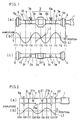
- Fig. 1 is a schematic diagram showing the positional relationship between a transducer, a resonator and ultrasonic vibration according to Embodiment 1 of the present invention.
- the transducer 1 is an electro-acoustic transducer or electric vibration transducer for converting electric energy into mechanical energy and formed of a piezoelectric element, a magnetostriction element or the like, which generates and outputs vibration of a vertical ultrasonic wave having a predetermined frequency with electric energy supplied from an unshown ultrasonic wave generator.
- To an output end of the transducer 1 is connected coaxially a resonator 2 by unshown headless screws and unshown screw holes.
- the resonator 2 is as long as 5/2 the wavelength of the resonance frequency to provide six maximum vibration amplitude points f1, f3, f5, f7, f9 and f11 and five minimum vibration amplitude points f2, f4, f6, f8 and 10 when it resonates with ultrasonic vibration transmitted from the transducer 1 as a vertical wave at a predetermined frequency.
- the resonator 2 comprises a bar-shaped ultrasonic horn 3 made of an alloy such as a titanium alloy and two bar-shaped boosters 4 and 5 made of titanium, aluminum or hardened iron.
- the two boosters 4 and 5 are connected to both sides of the ultrasonic horn 3 by unshown headless screws and unshown screw holes in such a manner that they are coaxial with the ultrasonic horn 3.
- the ultrasonic horn 3 is as long as 3/2 the wavelength from the maximum vibration amplitude point f3 to the maximum vibration amplitude point f9 and comprises a cross-shaped, when seen from the plane, vibration conversion portion 3a and two horn portions 3b and 3c connected to both sides of the conversion portion 3a by unshown headless screws and unshown screw holes in such a manner that they are coaxial with the conversion portion 3a.
- the vibration conversion portion 3a converts ultrasonic vibration transmitted from the transducer 1 in a straight direction and a direction perpendicular to the direction and has a ring-shaped bonding working portion 3d on the cross-shaped under surface thereof around the minimum vibration amplitude point f6.
- the bonding working portion 3d provides combined vibration energy of ultrasonic vibration in a straight direction and ultrasonic vibration in a perpendicular direction to the interface Wa (see Fig. 3).
- the ultrasonic horn 3 comprises heaters 6 and 7 at portions other than the bonding working portion 3d.
- the heaters 6 and 7 are electric heaters for converting electric energy into heat energy.
- the heater incorporates in a metal case an electrically insulated member for converting electric energy into heat energy and electric wires 6a and 7a projecting outside from the case and is attached to the resonator 2 by inserting the case into respective holes 3e and 3f formed in the horn portions 3b and 3c in a direction that they are parallel to the under surface at the minimum vibration amplitude points f4 and f8, respectively.
- the heater holes 3e and 3f are open to the rear surface located on the ultrasonic vibration bonding machine side of the ultrasonic horn 3.
- the electric wires 6a and 7a do not interfere the bonding work.
- the heater holes 3e and 3f which are open or closed on the front surface side can be applied, when the holes which are closed on the front surface side are used, the radiation rate of heat generated by the heaters 6 and 7 to the outside of the ultrasonic horn 3 from the opening on the front surface side is reduced and the transmission coefficient of heat from the heaters 6 and 7 to the ultrasonic horn 3 is improved.
- the bonding working portion 3d can be suitably heated with small heating energy of the heaters 6 and 7.
- the minimum vibration amplitude point f6 is located at the vibration conversion portion 3a, when a single heater similar to the heaters 6 and 7 is provided in the vibration conversion portion 3a as shown by a virtual line in Fig. lc in place of the heaters 6 and 7 provided in the horns 3b and 3c, heat can be stably provided to the bonding working portion 3d.
- the booster 4, one of the above two boosters 4 and 5, is as long as 1/2 the wavelength from the maximum vibration amplitude point fl to the maximum vibration amplitude point f3 and the other booster 5 is as long as 1/2 the wavelength from the maximum vibration amplitude point f9 to the maximum vibration amplitude point f11.
- the connection surfaces 9 and 10 between the booster 4 and the ultrasonic horn 3 and between the booster 5 and the ultrasonic horn 3 are located at the maximum vibration amplitude points f3 and f9, respectively.
- Support portions 4a and 5a are provided on the boosters 4 and 5 in such a manner that they project outward from the peripheral surfaces of the boosters 4 and 5 in a radial direction and are coaxial with the boosters 4 and 5, respectively.
- Instantaneous displacements of ultrasonic vibration generated by the resonator 2 which resonates with ultrasonic vibration from the transducer 1 are indicated by waveforms drawn by solid lines L1 and L2.
- the waveform shown by a solid line L1 indicates ultrasonic vibration which is transmitted from the transducer 1 and caused to go straight by the vibration conversion portion 3a and the waveform shown by a solid line L2 indicates ultrasonic vibration whose direction is converted into a perpendicular direction by the vibration conversion portion 3a.
- Fig. 2 is a schematic diagram showing the positional relationship among a transducer, a resonator and ultrasonic vibration according to Embodiment 2 of the present invention.
- a resonator 20 connected to the transducer 1 comprises two boosters 4 and 5 similar to those of Embodiment 1, which are connected to both sides of a bar-shaped ultrasonic horn 21 made of an alloy such as a titanium alloy by unshown headless screws and screw holes in such a manner that they are coaxial with the ultrasonic horn 21 and is as long as 2 times the wavelength of a resonance frequency to provide five maximum vibration amplitude points f21, f23, f25, f27 and f29 and four minimum vibration amplitude points f22, f24, f26 and f28.
- the ultrasonic horn 21 is as long as the wavelength from the maximum vibration amplitude point f23 to the maximum vibration amplitude point f27 and a bonding working portion 21a is provided at a center portion of the ultrasonic horn 21 in such a manner that it is located at the maximum vibration amplitude point f25 and projects outward from the peripheral surface of the ultrasonic horn 21 in a radial direction.
- the ultrasonic horn 21 comprises heaters 6 and 7 similar to those of Embodiment 1 at portions other than the bonding working portion 21a.
- the heaters 6 and 7 are inserted into heater holes 21b and 21c which are formed in the ultrasonic horn 21 in a direction that they are parallel to the under surface at the minimum vibration amplitude points f24 and f26 like Embodiment 1, respectively.
- Instantaneous displacement of ultrasonic vibration generated by the resonator 20 is indicated by a waveform drawn by a solid line L3.
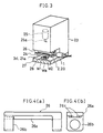
- Fig. 3 is a perspective view of an ultrasonic vibration bonding machine according to Embodiment 3 which uses the resonator 2 of Embodiment 1 or the resonator 20 of Embodiment 2.
- a main body 23 has a working space 24 which is open in forward, right and left directions at a front lower portion thereof and an air cylinder 25 inside an upper portion thereof for defining an upper portion of the working space 24.
- a holder 26 is installed at a lower end of a piston rod 25a projecting downward from the air cylinder 25. The holder 26 holds the resonator 2 or the resonator 20 connected to the transducer 1 from both sides thereof in such a manner that it is laid in an upper inside portion of the working space 24.
- a lower portion of the main body 23 for defining a rear portion of the working space 24 is set on a batholith 27 which constitutes a base for setting the ultrasonic vibration bonding machine in a production line, for example.
- a mount 28 for mounting an overlapped interface Wa of a plurality of members w1 and W2 to be bonded together is installed on top of the base 27.
- the mount 28 is arranged at a lower inner portion of the working space 24 in such a manner that it is coaxial with the piston rod 25a and the bonding working portion 3d or 21a in a vertical direction.
- the top surface of the mount 28 faces the under surface of the bonding working portion 3d or 21a in parallel with predetermined spacing therebetween in a vertical direction when the piston rod 25a stops at the upper limit position.
- the piston rod 25a of the air cylinder 25 contracts, the bonding working portion 3d or 21a moves up a predetermined distance in a direction perpendicular to the transmission direction of ultrasonic vibration from the transducer 1 to the resonator 2 or 20 and a direction that it parts from the mount 28 in an upward direction, the piston rod 25a stops contracting, and the bonding working portion 3d or 21a stops at the upper limit position, whereby a predetermined space for taking in and out the members W1 and W2 to be bonded together is formed between the under surface of the bonding working portion 3d or 21a and the top surface of the mount 28. While the bonding working portion 3d or 21a stops at the upper limit position, the members W1 and W2 are mounted in the bonding working area on the top of the mount 28 while they are placed one upon another.
- the interface Wa of the members W1 and W2 to be bonded together is pressure held between the bonding working portion 3d or 21a and the mount 28.
- a holder arm 26b is separated from the main body 26a of the holder 26 like Embodiment 4 shown in Fig. 4 and is slidably attached to the main body 26a by a guide mechanism such as a cross roller 26c in such a manner that it can slide along the axial direction of the resonator 2 or 20. Since part of the holder 26 is made movable in this way and the expansion and contraction of the resonator 2 or 20 caused by heat transmitted from the heaters 6 and 7 are absorbed, the energy loss of ultrasonic vibration can be reduced.
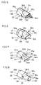
- Ultrasonic horns 30, 32, 34 and 36 according to Embodiments 4 to 7 shown in Figs. 5 to 8 are bar-shaped, made of an alloy such as a titanium alloy, and as long as 1/2 the wavelength of the frequency of ultrasonic vibration shown by virtual lines in these figures.
- the ultrasonic horn 30 of Embodiment 5 shown in Fig. 5 has upper and lower flat portions 30b for a fastening tool in a cylindrical portion 32a ranging from the maximum vibration amplitude point f30 to the minimum vibration amplitude point f31, an inclination portion 30c which inclines gradually toward the reference line (zero line) of vibration amplitude from the flat portions 30 at a section from the minimum vibration amplitude point f31 to the maximum vibration amplitude point f32, a plurality of rectangular bonding working portions 30d arranged in an array, spaced from one another and projecting upward and downward from the inclination portion 30c at the maximum vibration amplitude point f32, and a heater 31 like an electric heater inserted into a heater hole 30e in a direction parallel to the bonding working portion 30d at the minimum vibration amplitude point f31.
- Reference symbol 31a is an electric wire of the heater 31.
- the ultrasonic horn 32 of Embodiment 6 shown in Fig. 6 has upper and lower flat portions 32b for a fastening tool in the cylindrical portion 32a ranging from the maximumn vibration amplitude point f30 to the minimum vibration amplitude point f31, an inclination portion 32c which inclines gradually toward the reference line (zero line) of vibration amplitude from the flat portions 32b at a section from the minimum vibration amplitude point f31 to the maximum vibration amplitude point f32, a rectangular bonding working portion 32d projecting upward and downward from the inclination portion 32c at the maximum vibration amplitude point f32, and a heater 33 like an electric heater inserted into a heater hole 32e in a direction parallel to the bonding working portion 32d at the minimum vibration amplitude point f31.
- Reference symbol 33a is an electric wire of the heater 33.
- the ultrasonic horn 34 of Embodiment 7 shown in Fig. 7 has a recess portion 34b for a fastening tool in a cylindrical portion 34a ranging from the maximum vibration amplitude point f30 to the minimum vibration amplitude point f31, an inclination portion 34d for connecting a prismatic portion 34c ranging from the minimum vibration amplitude point f31 to the maximum vibration amplitude point f32 to the cylindrical portion 34a smoothly, a rectangular bonding portion 34e projecting from the prismatic portion 34c in a transverse direction at the maximum vibration amplitude point f32, and a heater 35 like an electric heater inserted into a heater hole 34f in a direction parallel to the bonding working portion 34e at the minimum vibration amplitude point f31.
- Reference symbol 35a is an electric wire of the heater 35.
- the ultrasonic horn 36 of Embodiment 8 shown in Fig. 8 has a recess portion 36b for a fastening tool in a large cylindrical portion 36a ranging from the maximum vibration amplitude point f30 to the minimum vibration amplitude point f31, an inclination portion 36d for connecting a small cylindrical portion 36c ranging from the minimum vibration amplitude point f31 to the maximum vibration amplitude point f32 to the cylindrical portion 36a smoothly, a plurality of rectangular bonding working portions 36e projecting from the cylindrical portion 36c in a radial direction at the maximum vibration amplitude point f32 and arranged in a circumferential direction with spacing therebetween, and a heater 37 like an electric heater inserted into a heater hole 36f in a direction parallel to the bonding working portions 36e at the minimum vibration amplitude point f31.
- Reference symbol 37a is an electric wire of the heater 37.
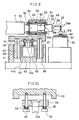
- Figs. 9 and 10 show an ultrasonic vibration bonding machine according to Embodiment 9 which uses one of the horns 30, 32, 34 and 36 of Embodiments 5 to 8 as resonator.
- a main body 40 has a base portion 41 of a pressuring mechanism on a half portion thereof.
- a recess portion 41a formed on the top of the base portion 41 contains an air cylinder 42 as a pressurizing source.
- a piston rod 42a which is installed on the top of the air cylinder 42 is connected to a holder 43.
- an upper end of the piston rod 42a is attached to a movable piece 44 arranged below the holder 43 in such a manner that it cannot be pulled down out of the movable piece 44.
- the movable piece 44 is fitted with guide rods 45 fixed to the under surface of the holder 43 in such a manner that it can move vertically, and is pressed upward by elastic materials 46 such as coil springs installed between lower end portions of the guide rods 45 projecting from the movable piece 44 and the movable piece 44.
- elastic materials 46 such as coil springs installed between lower end portions of the guide rods 45 projecting from the movable piece 44 and the movable piece 44.
- guide shafts 47 formed of spline shafts are attached to the under surface of the holder 43 in such a manner that they face downward.
- Each of the guide shafts 47 is fitted in and is in slide contact with a guide bush 48 attached to the base portion 41 for the guide shaft so that it can move vertically.
- a resonator 49 connected to the transducer 1 is mounted on top of the holder 43.
- the resonator 49 comprises a horn 36, for example in the shape of one of the horns 30, 32, 34 and 36 of Embodiments 5 to 8, and a booster 50.
- the booster 50 is incorporated in a vibration insulating support member 51 whose length is adjustable.
- the vibration insulating support member 51 stores the booster 50 within a first housing 54 to which a first diaphragm 52 is attached by screws 53 and stores a portion of the booster 50 projecting from the first housing 54 within a second housing 57 to which a second diaphragm 55 is attached by screws 56.
- the second housing 57 is screwed to the first housing 54 coaxially.
- a nut 58 fitted in the first housing 54 is fastened in a direction that it approaches the second housing 57, and this nut 58 and the second housing 57 which functions as a nut for the first housing 54 are bound tightly so as to adjust the total length of the vibration insulating support member 51 to be fitted to the booster 50.
- the transducer 1 is connected to a rear end of the booster 50 stored within the vibration insulating support member 51 coaxially through the first diaphragm 52 by unshown headless screws and unshown screw holes and the ultrasonic horn 36 is connected to a front end of the booster 50 coaxially through the second diaphragm 55 by unshown headless screws and unshown screw holes.
- the vibration insulating support member 51 is mounted on top of the holder 43 so that the transducer 1 and the resonator 49 are arranged in the holder 43 as shown in Fig. 9.
- a mount 59 is provided on the main body 40.
- the mount 59 has a heater 60 which is an electric heater inside the uppermost portion thereof for mounting the members W1 and W2 to be bonded together.
- the bonding working portion 36e is moved up a predetermined distance in a direction perpendicular to the transmission direction of ultrasonic vibration from the transducer 1 to the resonator 49 and in a direction that it parts from the mount 59 in an upward direction. Thereafter, the expansion of the air cylinder 42 is stopped to form a predetermined space for taking in and out the members W1 and W2 to be bonded together between the under surface of the bonding working portion 36e and the top surface of the mount 59. In this state, the members W1 and W2 to be bonded together are mounted in the bonding working area on top of the mount 59 while they are placed one upon another.
- the movable piece 44 compresses the elastic member 46 and moves down and hence, the elastic member 46 absorbs the impact energy of the bonding working portion 36e on the members W1 and W2. Thereafter, the interface Wa is pressure held between the bonding working portion 36e and the mount 59.
- electric energy is supplied to the transducer to an unshown ultrasonic wave generator to generate ultrasonic vibration and electric energy is also supplied to the heaters 37 and 60 to generate heat.
- Supply of electric energy for oscillating the transducer 1 may be carried out as follows, for example.
- An unshown sensor is provided in the holder 43 and a dock is provided in the movable piece 44 so that the sensor detects the dock when the elastic material 46 is compressed by a predetermined amount as shown in Fig. 10 and supply of electric energy to the transducer 1 from the ultrasonic wave generator is started by the detection signal to oscillate the transducer 1.
- the resonator 49 resonates with ultrasonic vibration from the transducer 1, and the bonding working portion 36e vibrates with the maximum vibration amplitude in a direction shown by an arrow X perpendicular to the pressurizing direction by the air cylinder 42 and is heated by the heaters 37 and 60 from side thereof.
- the resonator 49 resonates with ultrasonic vibration from the transducer 1, and the bonding working portion 36e vibrates with the maximum vibration amplitude in a direction shown by an arrow X perpendicular to the pressurizing direction by the air cylinder 42 and is heated by the heaters 37 and 60 from side thereof.
- the overlapped surfaces are non-fusion bonded together suitably in a short period of time without increasing the energy of ultrasonic vibration and pressure force.
- Figs. 11 and 12 show Embodiment 10 in which a heater 62 for heating with hot air is provided around an ultrasonic horn 61.
- the ultrasonic horn 61 is the same as the ultrasonic horn 36 shown in Fig. 8 except that the heater 37 and the heater hole 36f are excluded and a bonding working portion 61a corresponding to the bonding working portion 36e is provided and is incorporated in the holder 43 of the ultrasonic vibration bonding machine shown in Fig. 9.
- the heater 62 is a closed ring-shaped pipe surrounding the ultrasonic horn 61 without contact, inside of which an endless passage 62a is formed and an air outlet 62b is formed continuously in the inner wall facing the ultrasonic horn 61 of the pipe in an entire circumferential direction.
- the heater 62 is attached by a screw 65 to an end of a stay 64 installed on the holder 43 by a screw 63.
- the heater is arranged coaxial with the ultrasonic horn 61 to form a predetermined space 66 between the heater 62 and the ultrasonic horn 61.
- a hose 67 connected to the air outlet of a hot air generation source such as a blower equipped with an unshown electric heater is connected to part of the outer wall of the heater 62.
- Hot air 68 is introduced from the hose 67 into the endless passage 62a in such a manner that it circulates in a circumferential direction and is blown uniformly against the outer wall of the ultrasonic horn 61 from the air outlet 62b from the endless passage 62a so that the ultrasonic horn 61 is heated by the blown hot air 68 from side thereof.
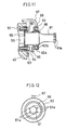
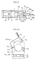
- Figs. 13 and 14 show an ultrasonic vibration bonding machine according to Embodiment 11 in which members which are made of a polymer compound such as a thermoplastic synthetic resin are bonded together by ultrasonic vibration.
- Fig. 13 shows a resonator 74 installed in a holder 71 by removing part of the holder 71, and
- Fig. 14 shows Embodiment 11 excluding the resonator 74 when seen from a direction shown by an arrow A in Fig. 13.
- the holder 71 attached to a main body 70 is driven vertically in a direction shown by an arrow Y1 by an air cylinder 72 attached to the main body 70 and guided along a guide mechanism 73 such as a cross roller installed between the main body 70 and the holder 71.
- the holder 71 comprises a holder portion 71a on the side of the guide mechanism and an open/close holder portion 71c attached to the holder portion 71a by a hinge 71b such that it can be opened or closed.
- Semi-circular recess portions 71d, 71e, 71f and 71g are formed in the interface between the holder portion 71a on the side of the guide mechanism and the open/close holder portion 71c.
- the resonator 74 is first stored in the recess portions 71d and 71e of the holder portion 71a on the side of the guide mechanism and the open/close holder portion 71c is then placed upon the holder portion 71a to hold the resonator 75 within the holder 71 by driving a screw 73 into a screw hole 71h formed in the top surface of the holder portion 71a on the side of the guide mechanism from a screw hole 71i formed in the bottom surface of the free end side of the open/close holder portion 71c.
- the resonator 74 connects a booster 75 to the transducer 1 coaxially by unshown headless screws and unshown screw holes and connects an ultrasonic horn 76 to the booster 75 coaxially by unshown headless screws and unshown screw holes.
- An intermediate portion of the transducer 1 is held between the recess portions 71d and 71f of the holder 71, a support portion 75a projecting outward coaxially from the booster 75 is held between the recess portion 71e and 71g of the holder 71.
- a step portion 71j projecting inward from the recess portions 71e and 71g of the holder 71 is installed in the holder 71 so that it can accept a support portion 75a of the booster at the time of bonding work.
- the ultrasonic horn 76 has a large base portion 76a on the side of the booster and a small bonding working portion 76b extended to the top from the base portion 76a and comprises an electric heater 77 inserted into a heater hole 76c formed at the minimum vibration amplitude point between the base portion 76a and the bonding working portion 76b.
- electric energy is supplied to the transducer 1 from an unshown ultrasonic wave generator to generate ultrasonic vibration, whereby the resonator 74 resonates and the ultrasonic horn 76 vibrates in a direction shown by an arrow Y2, and electric energy is supplied to the heater 77 to generate heat to heat the ultrasonic horn 76 from side thereof.
- the polymer compounds can be bonded together suitably in a short period of time.
- the ultrasonic horn may be various in shape such as a square bar having a plurality of bonding working portions on top and bottom surfaces in order to adjust the bonding working portion to the material of the member to be bonded and the physical properties such as area and thickness of the interface. Therefore, an ultrasonic horn the most suitable for the physical properties such as shape and material of the members to be bonded may be selected from among these ultrasonic horns.
- the resonator which is directly connected to an output end of the transducer has been illustrated.
- an intermediate booster may be used between the resonator and the transducer to change vibration amplitude at the bonding working portion.
- This intermediate booster is bar-shaped, as long as multiples of 1/2 the wavelength and made of titanium, aluminum or hardened iron, and changes the input/output ratio (magnification) of vibration amplitude by the volume ratio of a large diameter portion to a small diameter portion thereof.
- L4 shown in Figs. 5 to 8 is a waveform indicative of instantaneous displacement (vibration amplitude) of ultrasonic vibration caused by resonance.
- the resonance frequency changes according to the stretch of the resonator by heating. Then, according to the rule of thumb based on temperature dependence of resonance frequency, a resonator having a smaller length is manufactured at normal temperature. This resonator having a smaller length is stretched by heating at a predetermined temperature by a heater. As a matter of course, this stretched resonator is caused to resonate with ultrasonic vibration from the transducer so that the resonator can resonate with a predetermined frequency.
Landscapes
- Engineering & Computer Science (AREA)
- Mechanical Engineering (AREA)
- Physics & Mathematics (AREA)
- Fluid Mechanics (AREA)
- Thermal Sciences (AREA)
- Pressure Welding/Diffusion-Bonding (AREA)
- Apparatuses For Generation Of Mechanical Vibrations (AREA)
- Lining Or Joining Of Plastics Or The Like (AREA)
Claims (4)
- Ultraschall-Vibrationsschweißmaschine zum Verschweißen von Oberflächen einer Mehrzahl Elemente (W1, W2) an einer überlappten Berührungsfläche (Wa), wobei die Ultraschall-Schweißmaschine folgendes aufweist:dadurch gekennzeichnet, daßeine Aufnahme (28; 59) mit einem obersten Abschnitt zur Aufnahme der Mehrzahl Elemente (W1, W2) auf eine solche Weise, daß die Mehrzahl Elemente so angeordnet ist, daß die miteinander zu verschweißenden Oberflächen miteinander in Berührung stehen, um die überlappte Berührungsfläche (Wa) zu bilden;einen Resonator (2; 20; 49; 74) mit einem ersten Ende, einem zweiten Ende und einem Arbeitsabschnitt zum Verschweißen (3d; 21a; 30d; 32d; 34e; 36e; 61a; 76b), der zwischen dem ersten und zweiten Ende angeordnet ist;einen Wandler (1) mit einem Ausgangsende, das mit entweder dem ersten oder dem zweiten Ende des Resonators (2; 20; 49; 74) verbunden ist, wobei der Wandler (1) eine Ultraschallschwingung mit einer Resonanzfrequenz entsprechender Wellenlänge erzeugt;wobei die Schweißmaschine so eingerichtet ist, daß sie während des Betriebs über den Arbeitsabschnitt zum Verschweißen (3d; 21a; 30d; 32d; 34e; 36e; 61a; 76b) des Resonators (2; 20; 49; 74) Druck auf die überlappte Berührungsfläche (Wa) ausübt;wobei die Ultraschallschwingung vom Wandler (1) an den Arbeitsabschnitt zum Verschweißen (3d; 21a; 30d; 32d; 34e; 36e; 61a; 76b) des Resonators (2; 20; 49; 74) übertragen wird, um die Mehrzahl Elemente (W1, W2) zu verschweißen,der Resonator (2; 20; 49; 74) eine Länge gleich einem Mehrfachen der halben Wellenlänge der Resonanzfrequenz hat, so daß ein Punkt mit maximaler Schwingungsamplitude (f1, f11; f21, f29) an jedem des ersten und zweiten Endes des Resonators (2; 20; 49; 74) und ein Punkt mit minimaler Schwingungsamplitude (f2, f4, f6, f8, f10; f22, f24, f26, f28) am Resonator zwischen dem ersten und zweiten Ende gebildet wird; undein Heizelement (6, 7; 31; 33; 35; 37; 60; 77) so angeordnet ist, daß es zum obersten Abschnitt der Aufnahme (28; 59) gerichtet und im Punkt mit minimaler Schwingungsamplitude (f4, f8; f24, f26) des Resonators (2; 20; 49; 74) angeordnet ist.
- Ultraschall-Vibrationsschweißmaschine nach Anspruch 1, bei der eine Bohrung für ein Heizelement (3e, 3f; 21b; 21c; 30e; 32e; 34f; 36f; 76c) im Punkt mit minimaler Schwingungsamplitude des Resonators (2; 20; 49; 74) ausgeformt und ein elektrisches Heizelement (6, 7; 31; 33; 35; 37; 60; 77) in die Bohrung für das Heizelement (3e, 3f; 21b; 21c; 30e; 32e; 34f; 36f; 76c) so eingesetzt ist, daß es mit dem Resonator in Kontakt steht, wenn das Heizelement im Resonator (2; 20; 49; 74) vorgesehen ist.
- Ultraschall-Vibrationsschweißmaschine nach Anspruch 1, bei der ein weiteres Heizelement (60) im Innern des obersten Abschnitts der Aufnahme (59) eingebaut ist, wenn das Heizelement vorgesehen ist.
- Ultraschall-Vibrationsschweißmaschine nach einem der vorstehenden Ansprüche, bei der entweder der rechte oder der linke Halterungsarm (26), der den Resonator (2; 20; 49; 74) an beiden Enden trägt, am Hauptkörper der Halterung so befestigt ist, daß er in axialer Richtung entlang des Resonators gleiten kann, um die Berührungsfläche (Wa) zwischen der Aufnahme (28; 59) und dem Arbeitsabschnitt zum Verschweißen (3d; 21a; 30d; 32d; 34e; 36e; 61a; 76b) des Resonators (2; 20; 49; 74) mit Druck zu haltern, wenn von Aufnahme oder Resonator einer oder beide in einer solchen Richtung verfährt bzw. verfahren, daß sie sich einander nähern.
Applications Claiming Priority (6)
| Application Number | Priority Date | Filing Date | Title |
|---|---|---|---|
| JP213471/95 | 1995-08-22 | ||
| JP21347195 | 1995-08-22 | ||
| JP21347195 | 1995-08-22 | ||
| JP176726/96 | 1996-07-05 | ||
| JP08176726A JP3078231B2 (ja) | 1995-08-22 | 1996-07-05 | 超音波振動接合装置 |
| JP17672696 | 1996-07-05 |
Publications (2)
| Publication Number | Publication Date |
|---|---|
| EP0761371A1 EP0761371A1 (de) | 1997-03-12 |
| EP0761371B1 true EP0761371B1 (de) | 2000-04-19 |
Family
ID=26497524
Family Applications (1)
| Application Number | Title | Priority Date | Filing Date |
|---|---|---|---|
| EP96113503A Expired - Lifetime EP0761371B1 (de) | 1995-08-22 | 1996-08-22 | Ultraschallschwingungsschweissmaschine |
Country Status (8)
| Country | Link |
|---|---|
| US (1) | US5730832A (de) |
| EP (1) | EP0761371B1 (de) |
| JP (1) | JP3078231B2 (de) |
| KR (1) | KR100342663B1 (de) |
| CN (1) | CN1074966C (de) |
| CA (1) | CA2183476C (de) |
| DE (1) | DE69607798T2 (de) |
| TW (1) | TW316245B (de) |
Families Citing this family (53)
| Publication number | Priority date | Publication date | Assignee | Title |
|---|---|---|---|---|
| JP3099942B2 (ja) * | 1996-08-08 | 2000-10-16 | 株式会社アルテクス | 超音波振動接合用共振器 |
| JP3409683B2 (ja) * | 1998-03-17 | 2003-05-26 | 松下電器産業株式会社 | バンプ付電子部品のボンディングツールおよびボンディング装置 |
| US5906694A (en) * | 1998-03-31 | 1999-05-25 | American Technology, Inc. | Ultrasonic tube welding and cutting apparatus and method |
| JP3487166B2 (ja) * | 1998-04-21 | 2004-01-13 | 松下電器産業株式会社 | 電子部品のボンディングツールおよびボンディング装置 |
| JP3762111B2 (ja) * | 1998-08-31 | 2006-04-05 | 京セラ株式会社 | 超音波振動子 |
| EP1010492B1 (de) * | 1998-12-10 | 2004-09-01 | Ultex Corporation | Ultraschallschwingungsschweissverfahren |
| JP3290632B2 (ja) * | 1999-01-06 | 2002-06-10 | 株式会社アルテクス | 超音波振動接合装置 |
| CA2314733A1 (en) * | 1999-08-02 | 2001-02-02 | Ultex Corporation | Ultrasonic vibration bonding tool |
| JP3788351B2 (ja) * | 2002-01-21 | 2006-06-21 | 松下電器産業株式会社 | 電子部品のボンディング装置および電子部品のボンディングツール |
| US7243894B2 (en) * | 2002-02-15 | 2007-07-17 | 3M Innovative Properties Company | Mount for vibratory elements |
| US20040060639A1 (en) * | 2002-08-13 | 2004-04-01 | Dawn White | Method of apparatus for ensuring uniform build quality during object consolidation |
| DE10249569B4 (de) * | 2002-10-24 | 2005-03-17 | Robert Bosch Gmbh | Werkzeugkopf zum Befestigen eines elektrischen Leiters auf der Kontaktfläche eines Substrates und Verfahren zum Durchführen der Befestigung |
| JP3966217B2 (ja) * | 2003-04-23 | 2007-08-29 | 松下電器産業株式会社 | ボンディング装置およびボンディングツール |
| US7002283B2 (en) * | 2003-06-03 | 2006-02-21 | Asm Assembly Automation Ltd. | Ultrasonic transducer assembly |
| US6786384B1 (en) | 2003-06-13 | 2004-09-07 | 3M Innovative Properties Company | Ultrasonic horn mount |
| JP4278095B2 (ja) * | 2003-12-26 | 2009-06-10 | 本多電子株式会社 | 超音波放射体、超音波放射ユニット、超音波放射装置、及びこれを用いた超音波処理装置 |
| US7110625B2 (en) | 2004-09-16 | 2006-09-19 | Formguard Inc. | Apparatus to induce stress into a fiber optic cable to detect security fence climbing |
| DE102004045575A1 (de) * | 2004-09-17 | 2006-04-06 | Hesse & Knipps Gmbh | Ultraschalltransducer mit einem in der Lagerung angeordneten Sensor |
| KR100578139B1 (ko) * | 2004-10-05 | 2006-05-10 | 삼성전자주식회사 | 세정 프로브 및 이를 구비하는 메가소닉 세정 장비 |
| JP2006135249A (ja) * | 2004-11-09 | 2006-05-25 | Fujitsu Ltd | 超音波実装方法およびこれに用いる超音波実装装置 |
| US20060144906A1 (en) * | 2005-01-05 | 2006-07-06 | Sheehan James F | Ultrasonic welder with high-Q tool |
| JP2008078272A (ja) * | 2006-09-20 | 2008-04-03 | Athlete Fa Kk | 超音波振動接合装置 |
| JP2008218528A (ja) * | 2007-02-28 | 2008-09-18 | Fujitsu Ltd | 電子部品の実装方法および製造装置 |
| JP4941268B2 (ja) * | 2007-12-17 | 2012-05-30 | 富士通株式会社 | ワイヤボンディング方法およびワイヤボンディング装置 |
| JP5313751B2 (ja) * | 2008-05-07 | 2013-10-09 | パナソニック株式会社 | 電子部品装着装置 |
| JP4683100B2 (ja) * | 2008-09-17 | 2011-05-11 | パナソニック株式会社 | ボンディング装置およびボンディングツール |
| JP5281550B2 (ja) * | 2008-12-08 | 2013-09-04 | パナソニック株式会社 | ボンディングツール、電子部品装着装置、および電子部品装着方法 |
| JP5491081B2 (ja) * | 2009-06-22 | 2014-05-14 | 株式会社アルテクス | 超音波振動金属接合用共振器 |
| US7971769B2 (en) * | 2009-11-02 | 2011-07-05 | GM Global Technology Operations LLC | Quick change over tooling for a welder |
| EP2327534A1 (de) * | 2009-11-25 | 2011-06-01 | Telsonic Holding AG | Vorrichtung und Verfahren zum Verschweißen von Werkstücken |
| US8082966B2 (en) * | 2010-03-12 | 2011-12-27 | Edison Welding Institute, Inc. | System for enhancing sonotrode performance in ultrasonic additive manufacturing applications |
| JP5082081B2 (ja) * | 2010-07-20 | 2012-11-28 | 株式会社アドウェルズ | 超音波振動接合装置 |
| EP2457683A1 (de) * | 2010-11-25 | 2012-05-30 | Telsonic Holding AG | Torsionales Schweissen |
| US8408445B1 (en) * | 2011-09-30 | 2013-04-02 | GM Global Technology Operations LLC | Actively controlled vibration welding system and method |
| JP6273204B2 (ja) * | 2012-09-12 | 2018-01-31 | 株式会社Gsユアサ | 蓄電素子、及び蓄電素子の製造方法 |
| DE102013103887A1 (de) * | 2013-04-17 | 2014-10-23 | Schunk Sonosystems Gmbh | Ultraschallschweißvorrichtung |
| EP3068604B1 (de) | 2013-11-12 | 2019-09-18 | Dukane IAS, LLC | Verfahren zur ultraschallschweissung von thermoplastischen teilen |
| CN107922071B (zh) * | 2015-08-31 | 2020-10-09 | 凸版印刷株式会社 | 超声波密封装置 |
| KR101698837B1 (ko) | 2016-09-05 | 2017-01-23 | 화이버트론 주식회사 | 침입 감지 휀스 시스템 |
| US10052714B2 (en) * | 2016-10-14 | 2018-08-21 | Sonics & Materials, Inc. | Ultrasonic welding device with dual converters |
| US10381321B2 (en) | 2017-02-18 | 2019-08-13 | Kulicke And Soffa Industries, Inc | Ultrasonic transducer systems including tuned resonators, equipment including such systems, and methods of providing the same |
| EP3600700B1 (de) * | 2017-03-21 | 2025-06-11 | Telsonic Holding AG | Torsionales ultraschallbearbeitungssystem und verfahren zum abstimmen eines torsionsschwingers |
| KR101922184B1 (ko) * | 2017-07-25 | 2018-11-26 | 세메스 주식회사 | 기판 처리 장치 |
| US11135778B2 (en) | 2018-06-13 | 2021-10-05 | Dukane Ias, Llc | Methods for determining a melt layer thickness associated with a predetermined weld strength based on a correlation therebetween |
| DE102018132838A1 (de) * | 2018-12-19 | 2020-06-25 | Herrmann Ultraschalltechnik Gmbh & Co. Kg | Ultraschallschweißanlage mit Halterung |
| JP6757837B1 (ja) * | 2019-08-30 | 2020-09-23 | 株式会社高田工業所 | 超音波共振体の支持構造及び超音波振動加工装置 |
| US11697172B2 (en) * | 2019-09-05 | 2023-07-11 | Ohio State Innovation Foundation | Systems and methods for joining and repair using ultrasonic additive manufacturing with a contoured sonotrode |
| CN112438249B (zh) * | 2020-11-26 | 2022-07-08 | 贵州电网有限责任公司 | 一种基于地下光缆与电缆的管道驱鼠系统及方法 |
| US11434189B1 (en) | 2021-10-20 | 2022-09-06 | I-Mei Foods Co., Ltd. | Method for isolating curcuminoids from turmeric rhizome |
| EP4169523A1 (de) | 2021-10-20 | 2023-04-26 | I-Mei Foods Co., Ltd. | Methode zur isolation von curcuminoiden aus dem rhizom von kurkuma |
| US20240116127A1 (en) * | 2022-10-11 | 2024-04-11 | Asmpt Singapore Pte. Ltd. | Ultrasonic transducer operable at multiple resonant frequencies |
| US20240116126A1 (en) * | 2022-10-11 | 2024-04-11 | Asmpt Singapore Pte. Ltd. | Ultrasonic transducer operable at multiple resonant frequencies |
| KR102760328B1 (ko) * | 2023-12-12 | 2025-02-03 | 주식회사 태일테크 | 열 및 초음파 통합형 본딩용 공구혼 및 이를 이용한 본딩방법 |
Family Cites Families (11)
| Publication number | Priority date | Publication date | Assignee | Title |
|---|---|---|---|---|
| DE541116C (de) * | 1932-01-08 | Ernst Curt Loesche | Vorrichtung zum Abscheiden von Staub | |
| US3752380A (en) * | 1972-03-13 | 1973-08-14 | Branson Instr | Vibratory welding apparatus |
| US4514242A (en) * | 1982-04-23 | 1985-04-30 | Vercon Inc. | Methods for oscillatory bonding of dissimilar thermoplastic materials |
| US4462849A (en) * | 1982-04-23 | 1984-07-31 | Cosden Technology, Inc. | Method of oscillatory bonding |
| US4529115A (en) * | 1983-04-12 | 1985-07-16 | Fairchild Industries, Inc. | Thermally assisted ultrasonic welding apparatus and process |
| EP0367705A3 (de) * | 1988-10-31 | 1990-09-26 | International Business Machines Corporation | Laserunterstützte Ultraschallverbindung |
| DE4032192C2 (de) * | 1990-10-08 | 1994-05-26 | Michael Kising | Vorrichtung zum Erhitzen eines ultraschallbetriebenen Löt- oder Schweißkopfes |
| JP2558976B2 (ja) * | 1991-11-08 | 1996-11-27 | 松下電器産業株式会社 | 電子部品の電極とリードとの接合方法 |
| US5240166A (en) * | 1992-05-15 | 1993-08-31 | International Business Machines Corporation | Device for thermally enhanced ultrasonic bonding with localized heat pulses |
| GB2271306B (en) * | 1992-10-06 | 1995-06-07 | Emhart Inc | Tab process control system |
| JPH06342830A (ja) * | 1993-06-02 | 1994-12-13 | Matsushita Electric Ind Co Ltd | ワイヤボンディング方法とその装置 |
-
1996
- 1996-07-05 JP JP08176726A patent/JP3078231B2/ja not_active Expired - Fee Related
- 1996-08-16 CA CA002183476A patent/CA2183476C/en not_active Expired - Fee Related
- 1996-08-20 US US08/699,863 patent/US5730832A/en not_active Expired - Lifetime
- 1996-08-20 TW TW085110141A patent/TW316245B/zh not_active IP Right Cessation
- 1996-08-22 CN CN96119926A patent/CN1074966C/zh not_active Expired - Fee Related
- 1996-08-22 KR KR1019960034839A patent/KR100342663B1/ko not_active Expired - Fee Related
- 1996-08-22 EP EP96113503A patent/EP0761371B1/de not_active Expired - Lifetime
- 1996-08-22 DE DE69607798T patent/DE69607798T2/de not_active Expired - Lifetime
Also Published As
| Publication number | Publication date |
|---|---|
| JP3078231B2 (ja) | 2000-08-21 |
| CN1074966C (zh) | 2001-11-21 |
| JPH09122934A (ja) | 1997-05-13 |
| KR970009968A (ko) | 1997-03-27 |
| TW316245B (de) | 1997-09-21 |
| KR100342663B1 (ko) | 2002-11-23 |
| CN1150924A (zh) | 1997-06-04 |
| DE69607798T2 (de) | 2000-08-10 |
| CA2183476C (en) | 1999-03-23 |
| US5730832A (en) | 1998-03-24 |
| DE69607798D1 (de) | 2000-05-25 |
| EP0761371A1 (de) | 1997-03-12 |
| CA2183476A1 (en) | 1997-02-23 |
Similar Documents
| Publication | Publication Date | Title |
|---|---|---|
| EP0761371B1 (de) | Ultraschallschwingungsschweissmaschine | |
| CA2094425C (en) | Method and apparatus for processing workpieces by ultrasonic energy | |
| US9849627B2 (en) | Ultrasonic press using servo motor with delayed motion | |
| US7819158B2 (en) | Ultrasonic press using servo motor with integrated linear actuator | |
| US6605178B1 (en) | Ultrasonic sealer | |
| EP2106899B1 (de) | Ultraschallpresse mit Servomotor und verzögerter Bewegungstechnik | |
| JP5583179B2 (ja) | ボンディング装置 | |
| US11633920B2 (en) | Methods for determining a melt layer thickness associated with a predetermined weld strength based on a correlation therebetween | |
| US9993970B2 (en) | Cross seam joining device for joining a sealing seam for a flexible packaging | |
| JPH1190329A (ja) | 超音波装置 | |
| WO2008080888A1 (en) | Device for producing ultrasonic vibrations | |
| US4319902A (en) | Joining optical fiber end parts | |
| US20030201053A1 (en) | Method and apparatus for welding polymer fabrics | |
| EP0816000B1 (de) | Vorrichtung mit durch Ultraschall erregtem Lötbad | |
| US4585152A (en) | Method and apparatus for degating parts using ultrasonic energy | |
| US4265689A (en) | Methods of joining glass objects | |
| JP4270729B2 (ja) | ボンディングヘッド及びこれを備えたボンディング装置 | |
| Kazunari Adachi et al. | Construction of torsional-vibration systems with a hollow cylindrical bolt-clamped langevin-type transducer and their application to ultrasonic plastic welding | |
| JP7333725B2 (ja) | 超音波接合装置 | |
| KR20230057390A (ko) | 초음파 복합 진동 장치 및 반도체 장치의 제조 장치 | |
| US5326953A (en) | Wire electrode feeder for wirecut electrical discharge machine | |
| CN115971631A (zh) | 一种超声焊接装置及系统和一种超声焊接方法 | |
| JPH0146794B2 (de) |
Legal Events
| Date | Code | Title | Description |
|---|---|---|---|
| PUAI | Public reference made under article 153(3) epc to a published international application that has entered the european phase |
Free format text: ORIGINAL CODE: 0009012 |
|
| AK | Designated contracting states |
Kind code of ref document: A1 Designated state(s): DE FR GB |
|
| 17P | Request for examination filed |
Effective date: 19970616 |
|
| 17Q | First examination report despatched |
Effective date: 19971119 |
|
| GRAG | Despatch of communication of intention to grant |
Free format text: ORIGINAL CODE: EPIDOS AGRA |
|
| GRAG | Despatch of communication of intention to grant |
Free format text: ORIGINAL CODE: EPIDOS AGRA |
|
| GRAH | Despatch of communication of intention to grant a patent |
Free format text: ORIGINAL CODE: EPIDOS IGRA |
|
| GRAH | Despatch of communication of intention to grant a patent |
Free format text: ORIGINAL CODE: EPIDOS IGRA |
|
| GRAA | (expected) grant |
Free format text: ORIGINAL CODE: 0009210 |
|
| AK | Designated contracting states |
Kind code of ref document: B1 Designated state(s): DE FR GB |
|
| REF | Corresponds to: |
Ref document number: 69607798 Country of ref document: DE Date of ref document: 20000525 |
|
| ET | Fr: translation filed | ||
| PLBE | No opposition filed within time limit |
Free format text: ORIGINAL CODE: 0009261 |
|
| STAA | Information on the status of an ep patent application or granted ep patent |
Free format text: STATUS: NO OPPOSITION FILED WITHIN TIME LIMIT |
|
| 26N | No opposition filed | ||
| REG | Reference to a national code |
Ref country code: GB Ref legal event code: IF02 |
|
| PGFP | Annual fee paid to national office [announced via postgrant information from national office to epo] |
Ref country code: GB Payment date: 20080821 Year of fee payment: 13 |
|
| GBPC | Gb: european patent ceased through non-payment of renewal fee |
Effective date: 20090822 |
|
| PG25 | Lapsed in a contracting state [announced via postgrant information from national office to epo] |
Ref country code: GB Free format text: LAPSE BECAUSE OF NON-PAYMENT OF DUE FEES Effective date: 20090822 |
|
| PGFP | Annual fee paid to national office [announced via postgrant information from national office to epo] |
Ref country code: DE Payment date: 20110823 Year of fee payment: 16 Ref country code: FR Payment date: 20110901 Year of fee payment: 16 |
|
| REG | Reference to a national code |
Ref country code: FR Ref legal event code: ST Effective date: 20130430 |
|
| PG25 | Lapsed in a contracting state [announced via postgrant information from national office to epo] |
Ref country code: DE Free format text: LAPSE BECAUSE OF NON-PAYMENT OF DUE FEES Effective date: 20130301 |
|
| PG25 | Lapsed in a contracting state [announced via postgrant information from national office to epo] |
Ref country code: FR Free format text: LAPSE BECAUSE OF NON-PAYMENT OF DUE FEES Effective date: 20120831 |
|
| REG | Reference to a national code |
Ref country code: DE Ref legal event code: R119 Ref document number: 69607798 Country of ref document: DE Effective date: 20130301 |