EP0761279A2 - Wabenkörper, sein Herstellungsprozess, seine Verwendung und Heizgerät - Google Patents
Wabenkörper, sein Herstellungsprozess, seine Verwendung und Heizgerät Download PDFInfo
- Publication number
- EP0761279A2 EP0761279A2 EP96112964A EP96112964A EP0761279A2 EP 0761279 A2 EP0761279 A2 EP 0761279A2 EP 96112964 A EP96112964 A EP 96112964A EP 96112964 A EP96112964 A EP 96112964A EP 0761279 A2 EP0761279 A2 EP 0761279A2
- Authority
- EP
- European Patent Office
- Prior art keywords
- honeycomb structure
- honeycomb
- molded product
- cell wall
- structure according
- Prior art date
- Legal status (The legal status is an assumption and is not a legal conclusion. Google has not performed a legal analysis and makes no representation as to the accuracy of the status listed.)
- Granted
Links
Images
Classifications
-
- C—CHEMISTRY; METALLURGY
- C04—CEMENTS; CONCRETE; ARTIFICIAL STONE; CERAMICS; REFRACTORIES
- C04B—LIME, MAGNESIA; SLAG; CEMENTS; COMPOSITIONS THEREOF, e.g. MORTARS, CONCRETE OR LIKE BUILDING MATERIALS; ARTIFICIAL STONE; CERAMICS; REFRACTORIES; TREATMENT OF NATURAL STONE
- C04B38/00—Porous mortars, concrete, artificial stone or ceramic ware; Preparation thereof
- C04B38/0006—Honeycomb structures
-
- B—PERFORMING OPERATIONS; TRANSPORTING
- B01—PHYSICAL OR CHEMICAL PROCESSES OR APPARATUS IN GENERAL
- B01D—SEPARATION
- B01D39/00—Filtering material for liquid or gaseous fluids
- B01D39/14—Other self-supporting filtering material ; Other filtering material
- B01D39/20—Other self-supporting filtering material ; Other filtering material of inorganic material, e.g. asbestos paper, metallic filtering material of non-woven wires
- B01D39/2068—Other inorganic materials, e.g. ceramics
- B01D39/2072—Other inorganic materials, e.g. ceramics the material being particulate or granular
- B01D39/2075—Other inorganic materials, e.g. ceramics the material being particulate or granular sintered or bonded by inorganic agents
-
- F—MECHANICAL ENGINEERING; LIGHTING; HEATING; WEAPONS; BLASTING
- F01—MACHINES OR ENGINES IN GENERAL; ENGINE PLANTS IN GENERAL; STEAM ENGINES
- F01N—GAS-FLOW SILENCERS OR EXHAUST APPARATUS FOR MACHINES OR ENGINES IN GENERAL; GAS-FLOW SILENCERS OR EXHAUST APPARATUS FOR INTERNAL COMBUSTION ENGINES
- F01N3/00—Exhaust or silencing apparatus having means for purifying, rendering innocuous, or otherwise treating exhaust
- F01N3/02—Exhaust or silencing apparatus having means for purifying, rendering innocuous, or otherwise treating exhaust for cooling, or for removing solid constituents of, exhaust
- F01N3/021—Exhaust or silencing apparatus having means for purifying, rendering innocuous, or otherwise treating exhaust for cooling, or for removing solid constituents of, exhaust by means of filters
- F01N3/022—Exhaust or silencing apparatus having means for purifying, rendering innocuous, or otherwise treating exhaust for cooling, or for removing solid constituents of, exhaust by means of filters characterised by specially adapted filtering structure, e.g. honeycomb, mesh or fibrous
- F01N3/0222—Exhaust or silencing apparatus having means for purifying, rendering innocuous, or otherwise treating exhaust for cooling, or for removing solid constituents of, exhaust by means of filters characterised by specially adapted filtering structure, e.g. honeycomb, mesh or fibrous the structure being monolithic, e.g. honeycombs
-
- F—MECHANICAL ENGINEERING; LIGHTING; HEATING; WEAPONS; BLASTING
- F01—MACHINES OR ENGINES IN GENERAL; ENGINE PLANTS IN GENERAL; STEAM ENGINES
- F01N—GAS-FLOW SILENCERS OR EXHAUST APPARATUS FOR MACHINES OR ENGINES IN GENERAL; GAS-FLOW SILENCERS OR EXHAUST APPARATUS FOR INTERNAL COMBUSTION ENGINES
- F01N2330/00—Structure of catalyst support or particle filter
- F01N2330/06—Ceramic, e.g. monoliths
-
- Y—GENERAL TAGGING OF NEW TECHNOLOGICAL DEVELOPMENTS; GENERAL TAGGING OF CROSS-SECTIONAL TECHNOLOGIES SPANNING OVER SEVERAL SECTIONS OF THE IPC; TECHNICAL SUBJECTS COVERED BY FORMER USPC CROSS-REFERENCE ART COLLECTIONS [XRACs] AND DIGESTS
- Y02—TECHNOLOGIES OR APPLICATIONS FOR MITIGATION OR ADAPTATION AGAINST CLIMATE CHANGE
- Y02T—CLIMATE CHANGE MITIGATION TECHNOLOGIES RELATED TO TRANSPORTATION
- Y02T10/00—Road transport of goods or passengers
- Y02T10/10—Internal combustion engine [ICE] based vehicles
- Y02T10/12—Improving ICE efficiencies
-
- Y—GENERAL TAGGING OF NEW TECHNOLOGICAL DEVELOPMENTS; GENERAL TAGGING OF CROSS-SECTIONAL TECHNOLOGIES SPANNING OVER SEVERAL SECTIONS OF THE IPC; TECHNICAL SUBJECTS COVERED BY FORMER USPC CROSS-REFERENCE ART COLLECTIONS [XRACs] AND DIGESTS
- Y10—TECHNICAL SUBJECTS COVERED BY FORMER USPC
- Y10S—TECHNICAL SUBJECTS COVERED BY FORMER USPC CROSS-REFERENCE ART COLLECTIONS [XRACs] AND DIGESTS
- Y10S55/00—Gas separation
- Y10S55/30—Exhaust treatment
-
- Y—GENERAL TAGGING OF NEW TECHNOLOGICAL DEVELOPMENTS; GENERAL TAGGING OF CROSS-SECTIONAL TECHNOLOGIES SPANNING OVER SEVERAL SECTIONS OF THE IPC; TECHNICAL SUBJECTS COVERED BY FORMER USPC CROSS-REFERENCE ART COLLECTIONS [XRACs] AND DIGESTS
- Y10—TECHNICAL SUBJECTS COVERED BY FORMER USPC
- Y10T—TECHNICAL SUBJECTS COVERED BY FORMER US CLASSIFICATION
- Y10T428/00—Stock material or miscellaneous articles
- Y10T428/24—Structurally defined web or sheet [e.g., overall dimension, etc.]
- Y10T428/24149—Honeycomb-like
Definitions
- the present invention relates to a honeycomb structure, a process for its production, a diesel particulate filter consisting of a silicon carbide honeycomb structure, and a heating apparatus useful for the production of the honeycomb structure.
- a honeycomb structure made mainly of cordierite or silicon carbide has been proposed as a filter for collecting from an exhaust gas combustible fine particles such as soot which is considered to be a hazardous substance, such as a diesel particulate filter (hereinafter referred to as "DPF") for collecting combustible fine particles contained in an exhaust gas from a diesel engine.
- DPF diesel particulate filter
- Such DPF is mounted as a part of an exhaust gas system for a diesel engine, so that an exhaust gas will flow into the through-holes which are open at the inlet end face, and when it passes through the cell wall, combustible fine particles are collected, whereupon the exhaust gas freed from the combustible fine particles will flow out from the through-holes which are open at the outlet end face.
- the cell wall is required to have a porosity and a pore diameter suitable for collecting all or substantially all combustible fine particles while permitting the exhaust gas containing combustible fine particles to readily pass therethrough.
- a method for regeneration of DPF there may be mentioned, for example, a method wherein a combustion gas of a burner is directly jetted to burn off the combustible fine particles, a method wherein DPF is combined with a heating metal layer such as a nichrome wire heater for heating and incineration, or a method wherein an electric current is directly applied to DPF made of an electrically conductive material for self heat-generation to burn off the combustible fine particles.
- Japanese Examined Patent Publication No. 77442/1993 discloses DPF wherein, in a cell wall of a honeycomb structure, the volume of open porosity and the mean diameter of pores constituting the open porosity, are within a zone defined by boundary lines connecting coordinate points 1-G-5-2-3-4 (wherein point 1: open porosity 58.5%, mean diameter of pores 1 ⁇ m, point G: open porosity 46.8%, mean diameter of pores 12 ⁇ m, point 5: open porosity 39.5%, mean diameter of pores 15 ⁇ m, point 2: open porosity 33.0%, mean diameter of pores 15 ⁇ m, point 3: open porosity 52.5%, mean diameter of pores 20 ⁇ m, point 4: open porosity 90.0%, mean diameter of pores 1 ⁇ m).
- Japanese Unexamined Patent Publication No. 83689/1986 discloses a silicon carbide honeycomb structure wherein a number of through-holes are adjacent to one another in an axial direction as partitioned by a thin wall, wherein the partition wall is of a three dimensional network structure composed mainly of plate-like crystals having an average aspect ratio of from 2 to 50.
- Japanese Unexamined Patent Publication No. 7215/1982 U.S. Patent 4,293,357
- Japanese Unexamined Patent Publication No. 37480/1983 U.S. Patents 4,557,773 and No. 4,573,896 disclose a method wherein a film or the like is bonded to an end face of honeycomb, and then holes are formed at positions corresponding to the through-holes to be sealed, or a film having such holes preliminarily provided, is bonded to an end face of honeycomb, and then such holes will be sealed by a sealing material at an end face of honeycomb.
- Another object of the present invention is to provide a method for producing a uniform honeycomb structure excellent in such effects for collecting combustible fine particles at high productivity without causing cracking or fusing loss.
- Still another object of the present invention is to provide high performance DPF by using silicon carbide as the material for DPF and by increasing the effects for collecting combustible fine particles by controlling the surface characteristics of the cell wall, so that it is possible to reduce the size of DPF and to shorten the regeneration cycle.
- a further object of the present invention is to provide a process for producing an electrically conductive sintered body and a heating apparatus, whereby the electrically conductive molded product can be sintered with a uniform temperature distribution and under a stabilized condition even when heating is conducted at a high temperature rising condition.
- the present invention provides:
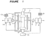
- a pair of electrodes i.e. the upper and lower electrodes (3) and (4) to conduct an electric current directly to an article (2) to be treated and a side heater (10) to externally heat the article to be treated, from the side surface thereof, wherein the pair of electrodes and the side heater are connected to the respective power supply control apparatus (5) to (9) and (11) to (15), and the lower electrode is movable up and down by an electrode moving apparatus (16).
- the honeycomb structure of the present invention may be made of such a material as a metal such as Al, Cr or Ni, ceramics such as silicon carbide, aluminum nitride, silicon nitride, alumina, cordierite or mullite, or a thermet such as Al 2 O 3 /Fe, Al 2 O 3 /Ni or B 4 C/Fe.
- silicon carbide is particularly suitable, since it has excellent heat resistance, and its porous body has a structure such that pores are formed at spaces among crystal particles which are entangled in a complicated state, whereby a gas permeation resistance is small, and the efficiency for collecting combustible fine particles is high.
- the surface roughness of the cell wall is specified to be at least 30 ⁇ m, preferably from 40 to 300 ⁇ m, by 10 point mean roughness (Rz), since the surface roughness of the cell wall is closely related to the collectable amount of combustible fine particles. If the surface roughness is less than 30 ⁇ m, the collectable amount of combustible fine particles can not be increased.
- the upper limit of the surface roughness of the cell wall is preferably 300 ⁇ m, taking the strength into consideration.
- the size of pores formed in the cell wall is controlled, even with a honeycomb structure having the above surface roughness.
- the open pore diameter at the cell wall surface i.e. the size of pores at their openings, is preferably at least 20 ⁇ m, more preferably from 20 to 50 ⁇ m. If this open pore diameter at the cell wall surface is less than 20 ⁇ m, clogging is likely to take place with a slight deposition of combustible fine particles, since the combustible fine particles have a strong adhesive force as they are formed by agglomeration of e.g. an oil component of a diesel engine.
- the upper limit of the open pore diameter at the cell wall surface is preferably 50 ⁇ m, taking the strength into consideration.
- the open pore diameter at the cell wall surface is meant for a mean diameter obtained by an image analysis upon observation of the cell wall surface by a scanning electron microscope.
- the measuring method will be described in detail in the following Examples.
- the mean pore diameter of pores formed in the cell wall is preferably at least 40%, more preferably from 50 to 70%, and the mean pore diameter is preferably from 10 to 40 ⁇ m. If the porosity of the cell wall is less than 40%, the gas permeation resistance tends to be high, and if it exceeds 70%, the strength will decrease. Further, if a mean diameter of pores in the cell wall is less than 10 ⁇ m, combustible fine particles tend to clog in the interior of the cell wall, and if it exceeds 40 ⁇ m, the strength tends to be low.
- the mean diameter of pores in the cell wall is meant for the one obtained by a mercury injection method.
- the measuring method will be described in detail in the following Examples.
- honeycomb structure of the present invention in the case of an electrically conductive honeycomb structure, in addition to DPF, a duct heater, a hot air-generating heater for a large sized dryer and various heaters for e.g. air conditioners, cooking devices, drying instruments and incineration furnaces, may be mentioned. Further, the honeycomb structure of the present invention may be used as a carrier for a catalyst for cleaning an exhaust gas.
- DPF consisting essentially of a silicon carbide honeycomb structure of the present invention has merits such that the collectable amount of combustible fine particles increases, and incineration of the collected combustible fine particles is facilitated, whereby cracking or fusing loss can be remarkably reduced.
- DPF of the present invention may be produced by sealing the honeycomb through-holes of the honeycomb structure of the present invention at its both end faces. Such sealing can be carried out by methods disclosed in the above-mentioned prior art references or by the method disclosed in Japanese Patent Application No. 171080/1995 by the present applicants.
- the process for producing a honeycomb structure according to the present invention is characterized in that a honeycomb shape molded product is formed of an electrically conductive material, and it is heated and sintered in a non-oxidizing atmosphere by conducting an electric current in the axial direction of the honeycomb through-holes.
- the cell wall undergoes self heat generation by conducting an electric current in the axial direction of the honeycomb through-holes, whereby crystal particles in the vicinity of the surface which have a larger free energy, can be preferentially sintered, and the surface roughness of the cell wall can be increased by the grain growth at that time.
- a non-oxidizing atmosphere such as nitrogen or argon
- the honeycomb shape molded product having an electrical conductivity to be used in the present invention, preferably has a resistance of at most 100 ⁇ , more preferably from 10 -1 to 10 2 ⁇ , at room temperature.
- heat generation and sintering can be carried out at a low voltage at a level of a few V to 50 V.
- the material for the honeycomb shape molded product may, for example, be electrically conductive ceramics such as titanium carbide, titanium nitride, titanium boride or molybdenum silicate, or its precursor such as a powder mixture of a metal titanium powder and carbon.
- non-conductive ceramics may also be used, and in such a case, an addition of a conductivity-imparting agent will be required to carry out sintering by conducting an electric current, and for such a purpose, a carbonaceous material is preferred.
- the carbonaceous material can readily be removed by heat treatment in an oxidizing atmosphere after sintering. Further, by adjusting the amount and the particle size thereof, it is possible to control the porosity, the pore diameter and the surface roughness of the honeycomb structure.
- Such non-conductive ceramics may, for example, be oxide type ceramics such as alumina, cordierite or mullite, or non-oxide ceramics such as silicon nitride, aluminum nitride or silicon carbide.
- silicon carbide is most suitable for DPF. Accordingly, the process for producing a silicon carbide honeycomb structure will be described in detail in the following.
- the silicon carbide honeycomb structure of the present invention can be prepared by molding a mixture comprising predetermined amounts of a silicon carbide powder, a silicon nitride powder and a carbonaceous material into a honeycomb shape molded product, which is then reaction-sintered.
- Merits in using such a honeycomb shape molded product are such that sintering can be carried out by conducting an electric current, since the molded product has a suitable electrical conductivity such that the resistance at room temperature is at most 100 ⁇ , preferably from 10 -1 to 10 2 ⁇ , and it is possible to control the porosity and the pore diameter of the honeycomb structure by adjusting the amount and the particle size of the silicon carbide powder.
- the surface roughness can be increased by controlling the growth of the crystal particles during the reaction sintering. With such merits, it is possible to produce DPF of high strength, which has good effects for collecting combustible fine particles.
- the mean particle diameter of the silicon carbide powder to be used in the present invention is preferably at most 50 ⁇ m, more preferably from 10 to 50 ⁇ m. If the mean particle diameter is less than 10 ⁇ m, the mean diameter of pores in the cell wall tends to be small, and if it exceeds 50 ⁇ m, the strength tends to be low. Further, the particle diameter of the silicon nitride powder is preferably at most 100 ⁇ m, more preferably at most 50 ⁇ m, from the viewpoint of the moldability and the carbonization reactivity.
- the carbonaceous material free carbon such as carbon black, acetylene black or graphite, or an organic resin which becomes carbon upon pyrolysis, such as phenol, furan or polyimide, may, for example, be used.
- the mean particle diameter of free carbon is preferably at most 10 ⁇ m, more preferably at most 1 ⁇ m.
- the proportions of the respective components in the mixture comprising the silicon carbide powder, the silicon nitride powder and the carbonaceous material are such that the silicon carbide powder is from 20 to 80 wt%, and the rest of from 80 to 20 wt% is substantially the silicon nitride powder and the carbonaceous material. Further, with respect to the proportions of the silicon nitride powder and the carbonaceous material, the molar ratio of the silicon content in the silicon nitride powder to the carbon content in the carbonaceous material (Si/C) is preferably from 0.5 to 1.5.
- the silicon carbide powder serves as aggregates in the reaction sintering.
- the strength tends to be low, and if it exceeds 80 wt%, the electrical resistance of the honeycomb shape molded product tends to be high, whereby the electrical sintering tends to be difficult, and the open pore diameter at the cell wall surface tends to be small.
- the Si/C molar ratio is less than 0.5, the grain growth of silicon carbide formed by carbonization tends to be hindered by the remaining carbon, whereby the mean diameter of pores in the cell wall tends to be small.
- the Si/C molar ratio is larger than 1.5, the unreacted silicon content formed by the decomposition of silicon nitride tends to be large, whereby the strength tends to be low, and when heating is carried out at a high temperature raising rate, the unreacted silicon content is likely to melt and soften, thus leading to sinter-cracking.
- a part of the silicon nitride powder is substituted by a silicon oxide powder, whereby it will be easy to increase the open pore diameter at the cell wall surface to a level of at least 20 ⁇ m. Further, it will be possible to produce a honeycomb structure having excellent effects for collecting combustible fine particles simply by carrying out external heating and sintering without carrying out the electrical heating and sintering.
- the proportion of the silicon oxide powder is preferably from 5 to 30 parts by weight, per 100 parts by weight of the silicon nitride powder. If the amount is less than 5 parts by weight, it tends to be difficult to increase the open pore diameter at the cell wall surface to a level of at least 20 ⁇ m. On the other hand, if it exceeds 30 parts by weight, the porosity of the cell wall tends to be too high, whereby the strength tends to be low, and in sintering under a high temperature rising rate, a large amount of CO gas will form suddenly by the reaction with the carbonaceous material, whereby sinter-cracking is likely to occur.
- the mean particle size of the silicon oxide powder is preferably at most 1 ⁇ m, whereby the effects for increasing the open pore diameter at the cell wall surface will be promoted.
- a binder and water are incorporated to the above mixture to obtain a kneaded product, which will then be extruded under high pressure from a die to form a honeycomb shape molded product.
- the kneaded product passing through the die surface has such a nature that a fine powder having a high fluidity tends to segregate even when it is attempted to reduce the friction with the die.
- this nature is utilized in such a manner that the silicon oxide powder having a mean particle size of at most 1 ⁇ m is segregated in the vicinity of the cell wall surface, and at the time of sintering, such a segregated silicon oxide powder is preferentially reacted with the carbonaceous material to generate CO gas, whereby the open pore diameter at the cell wall surface can be increased.
- the proportion of the carbonaceous material is preferably such that the molar ratio of the total silicon content in the silicon nitride powder and the silicon oxide powder to the carbon content in the carbonaceous material (Si/C) is from 0.5 to 1.5.
- any method may be employed so long as it is a method which is capable of uniformly mixing the mixture, such as dry or wet system mixing.
- suitable amounts of water and an organic binder such as methyl cellulose or polyvinyl alcohol, are incorporated to the mixture to obtain a kneaded product.
- the kneaded product is extrusion-molded into a honeycomb molded product of a desired shape and then heated and sintered.
- the heating and sintering is carried out in a non-oxidizing atmosphere such as nitrogen or argon by directly conducting an electric current in the axial direction of honeycomb through-holes.
- a non-oxidizing atmosphere such as nitrogen or argon
- electrical heating is desirable but not necessarily required, and sintering can be carried out by conventional external heating.
- the electrical heating is carried out after both end faces of the honeycomb shape molded product are pressed against a pair of electrodes made of e.g. carbon, silicon carbide, molybdenum silicate or metal under a face pressure of from 20 to 500 g/cm 2 .
- a pair of electrodes made of e.g. carbon, silicon carbide, molybdenum silicate or metal under a face pressure of from 20 to 500 g/cm 2 .
- the sintering temperature is preferably at least 1600°C, more preferably from 1800 to 2500°C. If the sintering temperature is lower than 1600°C, unreacted silicon nitride and carbonaceous material will remain, whereby the heat resistance tends to be low, and the grain growth of silicon carbide tends to be inadequate, whereby the surface roughness of the cell wall or the open pore diameter at the cell wall surface tend to be inadequate. On the other hand, if the sintering temperature exceeds 2500°C, crystal transformation or melting is likely to result, or the strength tends to be low due to extreme grain growth.
- the present invention it is preferred to conduct external heating by a side heater from the side surface of the honeycomb shape molded product, together with the above-mentioned electrical heating, at the time of heating and sintering the honeycomb shape molded product, as shown in Figure 1.
- the external heating is preferably carried out so that the temperature difference between the outer surface of the honeycomb shape molded product and the side heater will be within ⁇ 10%, particularly within ⁇ 5%.
- heating is carried out while adjusting the supply electric power to the electrodes and/or the side heater.
- Conventional silicon carbide honeycomb structures are produced by sintering a silicon carbide powder itself or a mixture of a silicon carbide powder and a sintering assistant, whereby the products will never have the surface roughness and open pore diameter at the cell wall surface, as specified by the present invention.
- the heating apparatus of the present invention is the one which is useful for heat treatment of an article to be treated by a combination of the electrical heating and the external heating by a side heater, whereby a honeycomb structure of the present invention can be produced when the article to be treated is a honeycomb shape molded product prepared from an electrically conductive material.
- the heating apparatus of the present invention comprises a heat treatment chamber (1), and, disposed therein, a pair of electrodes i.e. an upper electrode (3) and a lower electrode (4) to conduct an electric current directly to an article (2) to be treated and a side heater (10) to externally heat the article to be treated from its side surface, wherein the pair of electrodes and the side heater are connected to the respective power supply control apparatus.
- a pair of electrodes i.e. an upper electrode (3) and a lower electrode (4) to conduct an electric current directly to an article (2) to be treated and a side heater (10) to externally heat the article to be treated from its side surface, wherein the pair of electrodes and the side heater are connected to the respective power supply control apparatus.
- the article to be treated is set on the lower electrode, and the lower electrode is moved upwardly by a pneumatic or hydraulic electrode-moving apparatus (16), so that the upper end surface of the article to be treated is pressed against the upper electrode, whereupon the electric current is conducted.
- the temperature of the article to be treated is measured by a thermometer (6) via a temperature-measuring tube (5), and the controller (7) is actuated by the measured temperature, so that the output for controlling PID is supplied as a command signal to a control circuit, and the output of a thyristor (8) is controlled so that it agrees to the command signal, and the electric current is conducted to the article to be treated via a voltage/current controlling transformer (9).
- the side heater is disposed in the vicinity of the side wall portion of the article to be treated, and its temperature is measured by a thermometer (12) via a temperature measuring tube (11).
- a controller (13) is actuated in accordance with the measured value of the temperature, so that the output for controlling PID is supplied to a control circuit as a command signal, whereupon the output of a thyristor (14) is controlled so that it agrees with the command signal, and the electric current is conducted to the side heater via a voltage/current controlling transformer (15).
- the heat dissipation of the article to be treated can be efficiently suppressed by subjecting the article to be treated to the electric heating and the external heating by the side heater, and it becomes possible to heat the article with a uniform temperature distribution even when heating is carried out at a high temperature raising rate.
- the respective power supply control apparatus for the pair of electrodes and for the side heater are designed so that heating can be conducted with a uniform temperature distribution in accordance with a change in the heat dissipation corresponding to the shape of the article to be treated and a change in the resistance/temperature characteristics with a temperature rise corresponding to the material constituting the article to be treated, whereby it is possible to precisely control the temperature raising rate or the heat treating time and thereby to conduct the heat treatment constantly under a stabilized condition.
- an electrically conductive material such as carbon, silicon carbide, molybdenum silicate or a metal, may, for example, be used. However, it is preferred to make the heat capacity larger than the article to be treated, in order to suppress the heat generation of the electrode portions.
- the side heater is preferably disposed in parallel with the side wall of the article to be treated. Further, it is preferably disposed within 50 mm, more preferably within 20 mm, from the side wall of the article to be treated.
- the shape of the side heater is preferably a shape whereby the heat can be uniformly distributed to the side wall of the article to be treated, such as a rod shape or a surface shape. Especially from the viewpoint of the uniform heating and the power consumption by the side heater, it is preferred to employ a surface shape side heater and dispose it to completely surround the side wall of the article to be treated.
- a heating element of e.g. carbon, silicon carbide, molybdenum silicate or metal may, for example, be used.
- a carbon-molded board having a relative density of from 1 to 2 g/cm 3 having a small thermal capacity or a small change in the resistance/temperature characteristics is most suitable, whereby the power consumption can be minimized, and the temperature raising rate can be increased.
- this kneaded product was extrusion-molded into a honeycomb shape having an outer diameter size of 100 ⁇ 100 mm, a cell pitch of 2.0 mm and a cell wall thickness of 0.4 mm by means of a vacuum extrusion molding machine under a molding pressure of 80 kg/cm 2 , followed by cutting into a length of 100 mm.
- the obtained honeycomb shape molded product was dried and then heated to remove the binder at 450°C for 1 hour in a nitrogen atmosphere, followed by electrical heating and sintering.
- the electrical heating and sintering were carried out by conducting an electric current of 2000 A at the maximum in the axial direction while pressing both ends of the through-holes of the honeycomb shape molded product under a pressure of 100 g/cm 2 with carbon electrodes, raising the temperature to the sintering temperature as identified in Table 1 at a temperature raising rate of 50°C/min in a nitrogen atmosphere, and maintaining the molded product at the sintering temperature for 2 minutes.
- the obtained sintered product was subjected to oxidation treatment at 900°C for 3 hours in the atmosphere to burn off the remaining graphite, to obtain a honeycomb structure.
- Comparative Example 2 represents a case wherein electrical sintering was carried out while conducting an electric current in a direction vertical to the axis of the honeycomb through-holes
- Comparative Example 3 represents a case wherein the honeycomb shape molded product after removal of the binder was placed in a graphite crucible, and the graphite crucible was heated by a high frequency induction furnace at a temperature raising rate of 10°C/min in an argon atmosphere.
- Example 2 60 40 0.5 1650
- Example 3 50 50 0.1 1650 Comparative Example 1 100 0 >10 6 Impossible to raise the temp.
- Comparative Example 2 60 40 0.5 1650 Comparative Example 3 60 40 0.5 1650
- an alumina DPF excellent in the performance for collecting combustible fine particles can be obtained by adjusting the surface roughness (Rz) of the cell wall of the honeycomb structure to a level of at least 30 ⁇ m.
- a honeycomb structure was prepared in the same manner as in Example 1 except that using a mixture comprising a silicon carbide powder (mean particle diameter: 30 ⁇ m), a silicon nitride powder (mean particle diameter: 25 ⁇ m) and carbon black (mean particle diameter: 80 nm) in the proportions as identified in Table 3, the temperature was raised to the sintering temperature as identified in Table 3 at a rate of 50°C/min.
- Comparative Example 7 represents a case wherein electrical sintering was carried out by conducting an electric current in a direction vertical to the axis of the honeycomb through-holes
- Comparative Example 8 represents a case wherein sintering was carried out by a high frequency induction heating furnace.
- Comparative Example 7 Further, the properties in Comparative Example 7 were evaluated in the same manner as in Comparative Example 2. The results are shown in Table 4. Table 3 Mixture (wt%) Si/C molar ratio Resistance of honeycomb shape molded product ( ⁇ ) Sintering temp. (°C) Silicon carbide Silicon nitride Carbon black Example 4 20 63.6 16.4 1.0 0.5 1800 Example 5 40 47.7 12.3 1.0 0.7 2000 Example 6 60 31.8 8.2 1.0 0.7 2200 Example 7 80 15.9 4.1 1.0 95 2300 Example 8 40 39.6 20.4 0.5 0.2 2000 Example 9 40 51.2 8.8 1.5 0.7 1600 Example 10 60 32.9 7.1 1.2 1.0 1800 Example 11 40 45.4 14.6 0.8 0.7 2300 Example 12 60 31.8 8.2 1.0 0.7 2400 Comparative Example 4 15 67.6 17.4 1.0 0.5 1800 Comparative Example 5 85 11.9 3.1 1.0 ⁇ 10 3 Impossible to raise the temp.
- a silicon carbide DPF excellent in the performance for collecting combustible fine particles can be obtained by adjusting the surface roughness (Rz) of the cell wall of the honeycomb structure to a level of at least 30 ⁇ m.
- Examples represent cases wherein a silicon carbide honeycomb structure was prepared by conducting electrical heating and sintering in the same manner as in Examples 4 to 12. However, these Examples are different from Examples 4 to 12 in that a mixture having a part of the silicon nitride powder substituted by a silicon oxide powder, was used.
- Honeycomb structures were prepared and evaluated in the same manner as in Example 5 except that as shown in Table 5, mixtures having a part of the silicon nitride powder substituted variously by a silicon oxide powder (mean particle diameter: 0.5 ⁇ m), were used.
- Table 5 Mixture (wt%) Si/C molar ratio Resistance of honeycomb shape molded product ( ⁇ ) Silicon carbide Silicon nitride Silicon oxide Carbon black
- Example 5 40 47.7 0 12.3 1.0 0.7
- Example 13 40 45.5 2.3 12.2 1.0 0.7
- Example 14 40 43.6 4.3 12.1 1.0 0.7
- Example 15 40 37.1 11.1 11.8 1.0 0.7
- Table 6 Characteristics of cell wall of honeycomb structure Performance for collecting fine particles Honeycomb structure Porosity (%) Mean pore diameter ( ⁇ m) Surface roughness Rz ( ⁇ m) Open pore diameter ( ⁇ m) Initial pressure loss (mmHg) Amount of carbon deposited (g/m 2 ) Strength (MPa) Resistivity ( ⁇ cm)
- Honeycomb shape molded products were prepared, dried and heated to remove the binder in the same manner as in Examples 5 and 14. Each molded product was set on a pair of carbon electrodes and subjected to electrical heating and sintering under the conditions as identified in Table 7 in a nitrogen atmosphere, while conducting external heating by a side heater from its side surface, to obtain a honeycomb structure. Such an operation was repeated to prepare 10 honeycomb structures for each Example, and the crack-forming rate (%) and the internal fusing loss-forming rate (%) were measured.
- the results are shown in Table 7.
- Example 5 the temperature raising rate of the honeycomb shape molded product was increased from 50°C/min to 80°C/min, whereby the crack-forming rate was 10%, but the characteristics of the honeycomb structure free from formation of cracks, were equal to Example 5.
- a honeycomb shape molded product was prepared, dried, heated to remove the binder, placed in a graphite crucible and sintered in a nitrogen atmosphere at a rate of 10°C/min to the temperature as identified in Table 8 by a high frequency induction heating furnace to obtain a silicon carbide honeycomb structure.
- the results are shown in Table 9.
- Table 8 Mixture (wt%) Mean particle diameter of silicon oxide ( ⁇ m) Silicon oxide per 100 parts by weight of silicon nitride (parts by weight) Si/C molar ratio Sintering temp. (°C) Silicon carbide Silicon nitride Silicon oxide Graphite
- Example 20 20 53.4 10.7 15.9 0.3 20.0 1.0 1800
- Example 21 40 40.1 8.0 11.9 0.5 20.0 1.0 2000
- Example 22 80 13.3 2.7 4.0 1.0 20.0 1.0 2400
- Example 23 40 40.1 8.0 11.9 0.03 20.0 1.0 2000
- Example 24 40 45.5 2.3 12.2 0.3 5.0 1.0 2200
- Example 25 40 37.1 11.1 11.8 0.5 30.0 1.0 2000
- Example 26 40 33.4 6.7 19.9 0.3 20.0 0.5 2000
- Example 27 40 42.9 8.6 8.5 0.3 20.0 1.5 1600
- Example 28 40 40.1 8.0 11.9 0.3 20.0 1.0 2200
- Example 29 40 40.1 8.0 11.9 0.3 20.0 1.0 2400
Landscapes
- Chemical & Material Sciences (AREA)
- Engineering & Computer Science (AREA)
- Ceramic Engineering (AREA)
- Inorganic Chemistry (AREA)
- Organic Chemistry (AREA)
- General Engineering & Computer Science (AREA)
- Materials Engineering (AREA)
- Structural Engineering (AREA)
- Mechanical Engineering (AREA)
- Combustion & Propulsion (AREA)
- Life Sciences & Earth Sciences (AREA)
- Geology (AREA)
- Chemical Kinetics & Catalysis (AREA)
- Processes For Solid Components From Exhaust (AREA)
- Filtering Materials (AREA)
- Ceramic Products (AREA)
Applications Claiming Priority (3)
| Application Number | Priority Date | Filing Date | Title |
|---|---|---|---|
| JP21353795 | 1995-08-22 | ||
| JP213537/95 | 1995-08-22 | ||
| JP21353795 | 1995-08-22 |
Publications (3)
| Publication Number | Publication Date |
|---|---|
| EP0761279A2 true EP0761279A2 (de) | 1997-03-12 |
| EP0761279A3 EP0761279A3 (de) | 1997-05-02 |
| EP0761279B1 EP0761279B1 (de) | 2002-11-20 |
Family
ID=16640838
Family Applications (1)
| Application Number | Title | Priority Date | Filing Date |
|---|---|---|---|
| EP96112964A Expired - Lifetime EP0761279B1 (de) | 1995-08-22 | 1996-08-12 | Wabenkörper |
Country Status (3)
| Country | Link |
|---|---|
| US (1) | US5733352A (de) |
| EP (1) | EP0761279B1 (de) |
| DE (1) | DE69624884T2 (de) |
Cited By (9)
| Publication number | Priority date | Publication date | Assignee | Title |
|---|---|---|---|---|
| EP0882505A2 (de) * | 1997-06-06 | 1998-12-09 | Mitsubishi Heavy Industries, Ltd. | Honigwaben Katalysator und Verfahren zu seiner Herstellung |
| EP0884457A2 (de) * | 1997-06-12 | 1998-12-16 | Kabushiki Kaisha Toyota Chuo Kenkyusho | Teilchenfilter |
| WO2002002479A1 (en) * | 2000-06-30 | 2002-01-10 | Ngk Insulators, Ltd. | Honeycomb ceramic structure and method for preparation thereof |
| EP1489274A1 (de) † | 2002-03-04 | 2004-12-22 | Ibiden Co., Ltd. | Wabenfilter zur abgasdekontaminierung und abgasdekontaminierungsvorrichtung |
| WO2007012776A2 (fr) * | 2005-07-28 | 2007-02-01 | Saint-Gobain Centre De Recherches Et D'etudes Europeen | Support et filtre catalytique a base de carbure de silicium et a haute surface specifique |
| WO2007133492A2 (en) * | 2006-05-11 | 2007-11-22 | Corning Incorporated | Methods for the regeneration of monolytic activated carbon catalysts |
| FR2917405A1 (fr) * | 2007-06-18 | 2008-12-19 | Vibro Meter France Soc Par Act | Procede de preparation d'une ceramique frittee, ceramique ainsi obtenue et bougie d'allumage la comportant |
| EP2125668A1 (de) * | 2007-03-22 | 2009-12-02 | Posco | Poröser körper auf siliciumcarbidbasis und herstellungsverfahren dafür |
| US8246710B2 (en) | 2003-06-05 | 2012-08-21 | Ibiden Co., Ltd. | Honeycomb structural body |
Families Citing this family (39)
| Publication number | Priority date | Publication date | Assignee | Title |
|---|---|---|---|---|
| DE19917081B4 (de) * | 1998-04-16 | 2012-06-06 | Denso Corporation | Wabenförmige Struktur und Verfahren zu ihrer Herstellung |
| FR2796638B1 (fr) * | 1999-07-21 | 2001-09-14 | Ceramiques Tech Et Ind S A | Structure monolithe nid d'abeilles en materiau ceramique poreux, et utilisation comme filtre a particules |
| JP4094830B2 (ja) * | 2000-11-24 | 2008-06-04 | 日本碍子株式会社 | 多孔質ハニカムフィルター及びその製造方法 |
| JPWO2002096827A1 (ja) * | 2001-05-31 | 2004-09-09 | イビデン株式会社 | 多孔質セラミック焼結体及びその製造方法、ディーゼルパティキュレートフィルタ |
| JP4007058B2 (ja) * | 2001-08-06 | 2007-11-14 | 株式会社デンソー | 排ガス浄化フィルタ |
| US6699429B2 (en) * | 2001-08-24 | 2004-03-02 | Corning Incorporated | Method of making silicon nitride-bonded silicon carbide honeycomb filters |
| JP3927038B2 (ja) * | 2001-12-21 | 2007-06-06 | 日本碍子株式会社 | Si含有ハニカム構造体及びその製造方法 |
| JP2004000901A (ja) * | 2002-03-29 | 2004-01-08 | Ngk Insulators Ltd | 多孔質ハニカム構造体 |
| ATE481151T1 (de) * | 2003-02-28 | 2010-10-15 | Ibiden Co Ltd | Keramische wabenstruktur |
| DE602004006204T2 (de) | 2003-06-23 | 2008-01-10 | Ibiden Co., Ltd., Ogaki | Wabenstrukturkörper |
| US8661794B2 (en) * | 2003-08-29 | 2014-03-04 | Dow Global Technologies Llc | Diesel exhaust filter |
| PL1698388T3 (pl) * | 2003-12-26 | 2014-03-31 | Ngk Insulators Ltd | Sposób wytwarzania korpusu struktury plastra miodu |
| GB0405015D0 (en) * | 2004-03-05 | 2004-04-07 | Johnson Matthey Plc | Method of loading a monolith with catalyst and/or washcoat |
| JP4954705B2 (ja) * | 2004-09-14 | 2012-06-20 | 日本碍子株式会社 | 多孔質ハニカムフィルター |
| JP2007001836A (ja) * | 2005-06-27 | 2007-01-11 | Ngk Insulators Ltd | ハニカム構造体の製造方法 |
| FR2893861B1 (fr) * | 2005-11-30 | 2008-01-04 | Saint Gobain Ct Recherches | Structure de filtration d'un gaz a base de sic de porosite de surface de paroi controlee |
| CN101583408B (zh) * | 2007-01-30 | 2012-07-18 | 京瓷株式会社 | 蜂窝结构体及净化装置 |
| US20080202415A1 (en) * | 2007-02-28 | 2008-08-28 | David Paul Miller | Methods and systems for addition of cellulose ether to gypsum slurry |
| US7803296B2 (en) * | 2007-06-11 | 2010-09-28 | United States Gypsum Company | Methods and systems for preparing gypsum slurry containing a cellulose ether |
| WO2009020835A2 (en) | 2007-08-03 | 2009-02-12 | Errcive, Inc. | Porous bodies and methods |
| US9321692B2 (en) * | 2008-08-06 | 2016-04-26 | Honeywell International Inc. | Rapid synthesis of silicon carbide-carbon composites |
| EP3195929B1 (de) * | 2009-02-27 | 2019-09-25 | Inventys Thermal Technologies Inc. | Fluidkontaktor mit paralleler durchflussstruktur |
| US8277743B1 (en) | 2009-04-08 | 2012-10-02 | Errcive, Inc. | Substrate fabrication |
| US8359829B1 (en) | 2009-06-25 | 2013-01-29 | Ramberg Charles E | Powertrain controls |
| EP2455153B1 (de) | 2009-09-04 | 2018-10-31 | Hitachi Metals, Ltd. | Herstellungsverfahren für eine keramikwabenstruktur |
| WO2011064854A1 (ja) * | 2009-11-25 | 2011-06-03 | イビデン株式会社 | セラミック焼成体の製造方法及びハニカム構造体の製造方法 |
| CN102781555B (zh) * | 2010-02-26 | 2014-09-17 | 日本碍子株式会社 | 蜂窝构造体 |
| WO2011125225A1 (ja) * | 2010-04-09 | 2011-10-13 | イビデン株式会社 | ハニカム構造体及び排ガス浄化装置 |
| WO2011125228A1 (ja) * | 2010-04-09 | 2011-10-13 | イビデン株式会社 | ハニカム構造体 |
| WO2011125227A1 (ja) * | 2010-04-09 | 2011-10-13 | イビデン株式会社 | ハニカム構造体及び排ガス浄化装置 |
| WO2011125229A1 (ja) * | 2010-04-09 | 2011-10-13 | イビデン株式会社 | ハニカム構造体 |
| WO2011125226A1 (ja) * | 2010-04-09 | 2011-10-13 | イビデン株式会社 | ハニカム構造体 |
| US9833932B1 (en) | 2010-06-30 | 2017-12-05 | Charles E. Ramberg | Layered structures |
| EP2762229B1 (de) * | 2011-09-30 | 2016-07-27 | NGK Insulators, Ltd. | Wabenstruktur |
| JP5990095B2 (ja) * | 2012-12-18 | 2016-09-07 | 日本碍子株式会社 | 微粒子捕集フィルタ |
| JP6114023B2 (ja) * | 2012-12-18 | 2017-04-12 | 日本碍子株式会社 | 微粒子捕集フィルタ |
| JP6111122B2 (ja) * | 2013-03-29 | 2017-04-05 | 日本碍子株式会社 | ハニカム構造体及びその製造方法 |
| JP6022985B2 (ja) * | 2013-03-29 | 2016-11-09 | 日本碍子株式会社 | ハニカム構造体 |
| JP5992857B2 (ja) * | 2013-03-29 | 2016-09-14 | 日本碍子株式会社 | ハニカム構造体 |
Citations (6)
| Publication number | Priority date | Publication date | Assignee | Title |
|---|---|---|---|---|
| US4439929A (en) * | 1981-02-23 | 1984-04-03 | Ngk Insulators, Ltd. | Apparatus for drying a ceramic green honeycomb body |
| US4965101A (en) * | 1987-12-10 | 1990-10-23 | Swiss Aluminium Ltd. | Ceramic foam for filters for cleaning exhaust gases of diesel engines |
| JPH03253600A (ja) * | 1990-03-05 | 1991-11-12 | Fuji Photo Film Co Ltd | 印刷版用支持体の製造方法 |
| US5234659A (en) * | 1989-05-16 | 1993-08-10 | Moen Asbjoern | Plant for conductive electrical heating of steel blanks |
| EP0658363A1 (de) * | 1993-12-15 | 1995-06-21 | Ngk Insulators, Ltd. | Poröser keramischer Filter mit Bienenwabenstruktur |
| DE19522312A1 (de) * | 1994-06-21 | 1996-01-04 | Ngk Insulators Ltd | Abgasfilter und Vorrichtung zur Behandlung von Abgasen |
Family Cites Families (15)
| Publication number | Priority date | Publication date | Assignee | Title |
|---|---|---|---|---|
| JPS609844B2 (ja) * | 1979-03-07 | 1985-03-13 | 日本碍子株式会社 | 高温用セラミツクフイルタ− |
| JPS577215A (en) * | 1980-06-16 | 1982-01-14 | Ngk Insulators Ltd | Preparation of ceramic honeycomb filter |
| USRE31405E (en) * | 1980-07-03 | 1983-10-04 | Corning Glass Works | Ceramic foam cement |
| US4329162A (en) * | 1980-07-03 | 1982-05-11 | Corning Glass Works | Diesel particulate trap |
| US4300953A (en) * | 1980-07-03 | 1981-11-17 | Corning Glass Works | Dense cordierite containing manganese |
| US4297140A (en) * | 1980-07-03 | 1981-10-27 | Corning Glass Works | Ceramic foam cement |
| US4573896A (en) * | 1981-07-15 | 1986-03-04 | Corning Glass Works | Apparatus for selectively manifolding honeycomb structures |
| US4557773A (en) * | 1981-07-15 | 1985-12-10 | Corning Glass Works | Method for selectively manifolding honeycomb structures |
| JPS58174216A (ja) * | 1982-04-03 | 1983-10-13 | Ngk Spark Plug Co Ltd | 可燃性微粒子除去用フイルタ |
| JPS6183689A (ja) * | 1984-09-27 | 1986-04-28 | イビデン株式会社 | 炭化ケイ素質ハニカム構造体 |
| JPS637814A (ja) * | 1986-06-30 | 1988-01-13 | Ibiden Co Ltd | セラミツクフイルタ− |
| JP2529138B2 (ja) * | 1990-09-26 | 1996-08-28 | サッポロビール株式会社 | セラミックフィルタ―エレメント |
| US5126755A (en) * | 1991-03-26 | 1992-06-30 | Videojet Systems International, Inc. | Print head assembly for ink jet printer |
| DE69216101T2 (de) * | 1992-05-13 | 1997-07-17 | Sumitomo Electric Industries | Partikelfilter zur reinigung von dieselmotorabgas |
| JP3536060B2 (ja) * | 1995-07-06 | 2004-06-07 | 東京窯業株式会社 | セラミックハニカム構造体端面の目封じ方法 |
-
1996
- 1996-08-12 EP EP96112964A patent/EP0761279B1/de not_active Expired - Lifetime
- 1996-08-12 DE DE69624884T patent/DE69624884T2/de not_active Expired - Lifetime
- 1996-08-13 US US08/696,190 patent/US5733352A/en not_active Expired - Lifetime
Patent Citations (6)
| Publication number | Priority date | Publication date | Assignee | Title |
|---|---|---|---|---|
| US4439929A (en) * | 1981-02-23 | 1984-04-03 | Ngk Insulators, Ltd. | Apparatus for drying a ceramic green honeycomb body |
| US4965101A (en) * | 1987-12-10 | 1990-10-23 | Swiss Aluminium Ltd. | Ceramic foam for filters for cleaning exhaust gases of diesel engines |
| US5234659A (en) * | 1989-05-16 | 1993-08-10 | Moen Asbjoern | Plant for conductive electrical heating of steel blanks |
| JPH03253600A (ja) * | 1990-03-05 | 1991-11-12 | Fuji Photo Film Co Ltd | 印刷版用支持体の製造方法 |
| EP0658363A1 (de) * | 1993-12-15 | 1995-06-21 | Ngk Insulators, Ltd. | Poröser keramischer Filter mit Bienenwabenstruktur |
| DE19522312A1 (de) * | 1994-06-21 | 1996-01-04 | Ngk Insulators Ltd | Abgasfilter und Vorrichtung zur Behandlung von Abgasen |
Non-Patent Citations (3)
| Title |
|---|
| DATABASE WPI Section Ch, Week 8808 Derwent Publications Ltd., London, GB; Class F09, AN 88-052593 XP002019060 & JP-A-63 007 814 (IBIDEN CO LTD) , 13 January 1988 * |
| DATABASE WPI Section Ch, Week 9351 Derwent Publications Ltd., London, GB; Class A81, AN 93-410207 XP002019059 & JP-A-05 309 220 (FUJI DICE KK ET AL) , 22 November 1993 * |
| PATENT ABSTRACTS OF JAPAN vol. 016, no. 054 (C-0909), 12 February 1992 & JP-A-03 253600 (FUJI PHOTO FILM CO LTD), 12 November 1991, * |
Cited By (21)
| Publication number | Priority date | Publication date | Assignee | Title |
|---|---|---|---|---|
| EP0882505A2 (de) * | 1997-06-06 | 1998-12-09 | Mitsubishi Heavy Industries, Ltd. | Honigwaben Katalysator und Verfahren zu seiner Herstellung |
| EP0882505A3 (de) * | 1997-06-06 | 1999-04-14 | Mitsubishi Heavy Industries, Ltd. | Honigwaben Katalysator und Verfahren zu seiner Herstellung |
| US6156698A (en) * | 1997-06-06 | 2000-12-05 | Mitsubishi Heavy Industries, Ltd. | Honeycomb catalyst and manufacturing method therefor |
| EP0884457A2 (de) * | 1997-06-12 | 1998-12-16 | Kabushiki Kaisha Toyota Chuo Kenkyusho | Teilchenfilter |
| EP0884457A3 (de) * | 1997-06-12 | 1999-03-10 | Kabushiki Kaisha Toyota Chuo Kenkyusho | Teilchenfilter |
| WO2002002479A1 (en) * | 2000-06-30 | 2002-01-10 | Ngk Insulators, Ltd. | Honeycomb ceramic structure and method for preparation thereof |
| US6818580B2 (en) | 2000-06-30 | 2004-11-16 | Ngk Insulators, Ltd. | Honeycomb ceramics structure body and method for producing the same |
| EP1489274A1 (de) † | 2002-03-04 | 2004-12-22 | Ibiden Co., Ltd. | Wabenfilter zur abgasdekontaminierung und abgasdekontaminierungsvorrichtung |
| EP1489274B2 (de) † | 2002-03-04 | 2013-06-05 | Ibiden Co., Ltd. | Verwendung eines wabenfilters zur abgasreinigung |
| US8246710B2 (en) | 2003-06-05 | 2012-08-21 | Ibiden Co., Ltd. | Honeycomb structural body |
| WO2007012776A3 (fr) * | 2005-07-28 | 2007-05-10 | Saint Gobain Ct Recherches | Support et filtre catalytique a base de carbure de silicium et a haute surface specifique |
| US7985274B2 (en) | 2005-07-28 | 2011-07-26 | Saint-Gobain Centre De Recherches Et D'etudes Europeen | High specific surface silicon carbide catalytic filter and support |
| FR2889080A1 (fr) * | 2005-07-28 | 2007-02-02 | Saint Gobain Ct Recherches | Support et filtre catalytique a base de carbure de silicium et a haute surface specifique |
| WO2007012776A2 (fr) * | 2005-07-28 | 2007-02-01 | Saint-Gobain Centre De Recherches Et D'etudes Europeen | Support et filtre catalytique a base de carbure de silicium et a haute surface specifique |
| WO2007133492A2 (en) * | 2006-05-11 | 2007-11-22 | Corning Incorporated | Methods for the regeneration of monolytic activated carbon catalysts |
| WO2007133492A3 (en) * | 2006-05-11 | 2008-04-03 | Corning Inc | Methods for the regeneration of monolytic activated carbon catalysts |
| US7781361B2 (en) | 2006-05-11 | 2010-08-24 | Corning Incorporated | Method for regeneration of activated carbon catalyst beds |
| EP2125668A1 (de) * | 2007-03-22 | 2009-12-02 | Posco | Poröser körper auf siliciumcarbidbasis und herstellungsverfahren dafür |
| EP2125668A4 (de) * | 2007-03-22 | 2010-08-18 | Posco | Poröser körper auf siliciumcarbidbasis und herstellungsverfahren dafür |
| FR2917405A1 (fr) * | 2007-06-18 | 2008-12-19 | Vibro Meter France Soc Par Act | Procede de preparation d'une ceramique frittee, ceramique ainsi obtenue et bougie d'allumage la comportant |
| EP2008986A1 (de) * | 2007-06-18 | 2008-12-31 | Vibro Meter France | Verfahren zur Herstellung einer Sinterkeramik, so erhaltene Keramik und Zündkerze, die sie umfasst |
Also Published As
| Publication number | Publication date |
|---|---|
| EP0761279A3 (de) | 1997-05-02 |
| DE69624884T2 (de) | 2003-09-11 |
| US5733352A (en) | 1998-03-31 |
| EP0761279B1 (de) | 2002-11-20 |
| DE69624884D1 (de) | 2003-01-02 |
Similar Documents
| Publication | Publication Date | Title |
|---|---|---|
| EP0761279B1 (de) | Wabenkörper | |
| JP4246802B2 (ja) | ハニカム構造体とその製造方法及び用途、並びに加熱装置 | |
| EP1364928B1 (de) | Wabenförmige struktur | |
| EP1506948B1 (de) | Wabenförmiger strukturkörper | |
| US6849213B2 (en) | Method for producing silicon nitride filter | |
| KR100516537B1 (ko) | Si함유 하니콤 구조체 및 그 제조 방법 | |
| JP2002201082A (ja) | ハニカム構造体及びその製造方法 | |
| JP2003154224A (ja) | 窒化ケイ素結合炭化ケイ素ハニカムフィルタの製造方法 | |
| WO2009118862A1 (ja) | ハニカム構造体の製造方法 | |
| JP3681780B2 (ja) | 多孔質導電性炭化珪素焼結体とその製造方法及び用途 | |
| JP3185960B2 (ja) | 多孔質チタン酸アルミニウム焼結体の製造方法 | |
| JP3642836B2 (ja) | 炭化珪素ハニカム構造体及びその製造方法 | |
| JP3461615B2 (ja) | ハニカム構造体及びその製造方法 | |
| JP5415382B2 (ja) | 導電性炭化珪素質多孔体の製造方法 | |
| JP5208900B2 (ja) | ディーゼルパティキュレートフィルタ用の導電性炭化珪素質多孔体の製造方法 | |
| JPS6061019A (ja) | 集塵用セラミツクスフイルタ | |
| JPH06107476A (ja) | マイクロ波再生可能な排ガス浄化用SiC多孔体 | |
| JP2002226271A (ja) | 多孔質炭化珪素焼結体の製造方法 | |
| KR100369210B1 (ko) | 다공성 세라믹 발열체, 그의 제조방법 및 그를 이용한 배기가스 필터 | |
| JP3691536B2 (ja) | 多孔質導電性炭化珪素焼結体の製造方法 | |
| JPH0812462A (ja) | 導電性セラミックとその製造方法及び用途 | |
| JP2728457B2 (ja) | 導電性炭化ケイ素焼結多孔体の製造方法 | |
| JP4041879B2 (ja) | セラミックス多孔体及びその製造方法 | |
| JP5539815B2 (ja) | 導電性を有する多孔質の炭化珪素質セラミックス焼結体 | |
| JPH07330462A (ja) | 多孔質SiC焼結体とその製造方法 |
Legal Events
| Date | Code | Title | Description |
|---|---|---|---|
| PUAI | Public reference made under article 153(3) epc to a published international application that has entered the european phase |
Free format text: ORIGINAL CODE: 0009012 |
|
| AK | Designated contracting states |
Kind code of ref document: A2 Designated state(s): DE FR GB |
|
| PUAL | Search report despatched |
Free format text: ORIGINAL CODE: 0009013 |
|
| AK | Designated contracting states |
Kind code of ref document: A3 Designated state(s): DE FR GB |
|
| 17P | Request for examination filed |
Effective date: 19970903 |
|
| 17Q | First examination report despatched |
Effective date: 19980710 |
|
| RTI1 | Title (correction) |
Free format text: HONEYCOMB STRUCTURE |
|
| GRAG | Despatch of communication of intention to grant |
Free format text: ORIGINAL CODE: EPIDOS AGRA |
|
| GRAG | Despatch of communication of intention to grant |
Free format text: ORIGINAL CODE: EPIDOS AGRA |
|
| GRAH | Despatch of communication of intention to grant a patent |
Free format text: ORIGINAL CODE: EPIDOS IGRA |
|
| GRAH | Despatch of communication of intention to grant a patent |
Free format text: ORIGINAL CODE: EPIDOS IGRA |
|
| GRAA | (expected) grant |
Free format text: ORIGINAL CODE: 0009210 |
|
| AK | Designated contracting states |
Kind code of ref document: B1 Designated state(s): DE FR GB |
|
| REG | Reference to a national code |
Ref country code: GB Ref legal event code: FG4D |
|
| REF | Corresponds to: |
Ref document number: 69624884 Country of ref document: DE Date of ref document: 20030102 |
|
| ET | Fr: translation filed | ||
| PLBE | No opposition filed within time limit |
Free format text: ORIGINAL CODE: 0009261 |
|
| STAA | Information on the status of an ep patent application or granted ep patent |
Free format text: STATUS: NO OPPOSITION FILED WITHIN TIME LIMIT |
|
| 26N | No opposition filed |
Effective date: 20030821 |
|
| REG | Reference to a national code |
Ref country code: GB Ref legal event code: 732E |
|
| REG | Reference to a national code |
Ref country code: FR Ref legal event code: TP |
|
| REG | Reference to a national code |
Ref country code: FR Ref legal event code: PLFP Year of fee payment: 20 |
|
| PGFP | Annual fee paid to national office [announced via postgrant information from national office to epo] |
Ref country code: DE Payment date: 20150804 Year of fee payment: 20 Ref country code: GB Payment date: 20150812 Year of fee payment: 20 |
|
| PGFP | Annual fee paid to national office [announced via postgrant information from national office to epo] |
Ref country code: FR Payment date: 20150629 Year of fee payment: 20 |
|
| REG | Reference to a national code |
Ref country code: DE Ref legal event code: R071 Ref document number: 69624884 Country of ref document: DE |
|
| REG | Reference to a national code |
Ref country code: GB Ref legal event code: PE20 Expiry date: 20160811 |
|
| PG25 | Lapsed in a contracting state [announced via postgrant information from national office to epo] |
Ref country code: GB Free format text: LAPSE BECAUSE OF EXPIRATION OF PROTECTION Effective date: 20160811 |