EP0756038B1 - Auslaufarmatur - Google Patents
Auslaufarmatur Download PDFInfo
- Publication number
- EP0756038B1 EP0756038B1 EP96110931A EP96110931A EP0756038B1 EP 0756038 B1 EP0756038 B1 EP 0756038B1 EP 96110931 A EP96110931 A EP 96110931A EP 96110931 A EP96110931 A EP 96110931A EP 0756038 B1 EP0756038 B1 EP 0756038B1
- Authority
- EP
- European Patent Office
- Prior art keywords
- outlet
- fitting according
- outlet fitting
- tubular guide
- water
- Prior art date
- Legal status (The legal status is an assumption and is not a legal conclusion. Google has not performed a legal analysis and makes no representation as to the accuracy of the status listed.)
- Expired - Lifetime
Links
- XLYOFNOQVPJJNP-UHFFFAOYSA-N water Substances O XLYOFNOQVPJJNP-UHFFFAOYSA-N 0.000 claims abstract description 41
- 230000008878 coupling Effects 0.000 claims description 8
- 238000010168 coupling process Methods 0.000 claims description 8
- 238000005859 coupling reaction Methods 0.000 claims description 8
- 238000011144 upstream manufacturing Methods 0.000 claims description 8
- 238000010276 construction Methods 0.000 claims description 3
- 239000007921 spray Substances 0.000 claims 5
- 238000005273 aeration Methods 0.000 claims 2
- 230000015572 biosynthetic process Effects 0.000 description 3
- 238000005276 aerator Methods 0.000 description 2
- 230000007257 malfunction Effects 0.000 description 2
- 239000000463 material Substances 0.000 description 2
- 238000006073 displacement reaction Methods 0.000 description 1
- 238000010438 heat treatment Methods 0.000 description 1
- 238000001746 injection moulding Methods 0.000 description 1
- 238000004519 manufacturing process Methods 0.000 description 1
- 238000000034 method Methods 0.000 description 1
- 230000000284 resting effect Effects 0.000 description 1
- 239000008400 supply water Substances 0.000 description 1
- 238000005406 washing Methods 0.000 description 1
- 238000003466 welding Methods 0.000 description 1
Images
Classifications
-
- E—FIXED CONSTRUCTIONS
- E03—WATER SUPPLY; SEWERAGE
- E03C—DOMESTIC PLUMBING INSTALLATIONS FOR FRESH WATER OR WASTE WATER; SINKS
- E03C1/00—Domestic plumbing installations for fresh water or waste water; Sinks
- E03C1/02—Plumbing installations for fresh water
- E03C1/08—Jet regulators or jet guides, e.g. anti-splash devices
- E03C1/084—Jet regulators with aerating means
-
- E—FIXED CONSTRUCTIONS
- E03—WATER SUPPLY; SEWERAGE
- E03C—DOMESTIC PLUMBING INSTALLATIONS FOR FRESH WATER OR WASTE WATER; SINKS
- E03C1/00—Domestic plumbing installations for fresh water or waste water; Sinks
- E03C1/02—Plumbing installations for fresh water
- E03C1/04—Water-basin installations specially adapted to wash-basins or baths
- E03C1/0404—Constructional or functional features of the spout
-
- E—FIXED CONSTRUCTIONS
- E03—WATER SUPPLY; SEWERAGE
- E03C—DOMESTIC PLUMBING INSTALLATIONS FOR FRESH WATER OR WASTE WATER; SINKS
- E03C1/00—Domestic plumbing installations for fresh water or waste water; Sinks
- E03C1/02—Plumbing installations for fresh water
- E03C1/04—Water-basin installations specially adapted to wash-basins or baths
- E03C2001/0415—Water-basin installations specially adapted to wash-basins or baths having an extendable water outlet
-
- E—FIXED CONSTRUCTIONS
- E03—WATER SUPPLY; SEWERAGE
- E03C—DOMESTIC PLUMBING INSTALLATIONS FOR FRESH WATER OR WASTE WATER; SINKS
- E03C1/00—Domestic plumbing installations for fresh water or waste water; Sinks
- E03C1/02—Plumbing installations for fresh water
- E03C1/04—Water-basin installations specially adapted to wash-basins or baths
- E03C2001/0417—Water-basin installations specially adapted to wash-basins or baths having space-saving features, e.g. retractable, demountable
-
- Y—GENERAL TAGGING OF NEW TECHNOLOGICAL DEVELOPMENTS; GENERAL TAGGING OF CROSS-SECTIONAL TECHNOLOGIES SPANNING OVER SEVERAL SECTIONS OF THE IPC; TECHNICAL SUBJECTS COVERED BY FORMER USPC CROSS-REFERENCE ART COLLECTIONS [XRACs] AND DIGESTS
- Y10—TECHNICAL SUBJECTS COVERED BY FORMER USPC
- Y10T—TECHNICAL SUBJECTS COVERED BY FORMER US CLASSIFICATION
- Y10T137/00—Fluid handling
- Y10T137/9464—Faucets and spouts
Definitions
- the invention relates to an outlet fitting, in particular for sinks and / or washstands, with one on a stationary one Housing pivoted pipe guide for the passage of a flexible hose line and to hold and hold one over the hose line outlet mouthpiece supplied with water.
- Such an outlet fitting was from the publication DE-A-31 35 860 known.
- the outlet mouthpiece in a shower with one arranged in the direction of the pipe guide, provided tubular handle.
- the invention has for its object to improve the outlet fitting specified in the preamble of claim 1 and to design it so that an extremely versatile use is made possible with a compact and inexpensive construction.
- This object is achieved in that the pipe guide is U-shaped and removable and attachable by the user to the stationary housing, while the free end area is directed into a basin, the outlet mouthpiece being provided with a stop formation which is in the plug-in position on the free End area of the pipe guide comes to the system. Further refinements of the invention are specified in claims 2 to 17.
- the guide tube in the U-shaped region is expediently curved around an arc of 135 ° to 200 °.
- the pipe guide can be provided at one end area with an attachment for receiving it in the housing of the outlet fitting, a snap lock or coupling can be formed in the housing for secure axial mounting, into which the attachment engages with a circumferential annular groove in the plug-in position, so that it is ensured that an unintentional loosening of the pipe guide from the housing of the outlet fitting is excluded.
- a backflow preventer can be expediently integrated in the housing of the outlet mouthpiece, so that an inadmissible sucking back of dirty water at a negative pressure in the supply line network, which can occur in the event of a malfunction, is prevented.
- the backflow preventer is expediently arranged in an extension of the housing to which the hose line is fastened with a union nut screw connection.
- the outlet mouthpiece is provided with a first outlet opening for producing a bundled water jet and a multiplicity of further outlet openings for producing shower jets, a switch being provided in the outlet mouthpiece, with which the inflowing water optionally to the opening for generating a bundled water jet or can be directed to the openings for generating shower jets.
- Both a radial slide valve can be provided as a change-over switch, the end regions of which protrude from the outer wall of the outlet mouthpiece and the outlet openings can alternatively be supplied with water by means of a displacement with the aid of a passage slide formed in the radial slide valve, and also with a rotary slide valve, in which the flow is downstream located housing part of the outlet mouthpiece is rotatable about a central axis with respect to the upstream housing part, so that alternatively the opening for generating a bundled water jet or the openings for generating shower jets is supplied with water with a bore formed off-center in the upstream housing part can be.
- a commercially available water jet aerator nozzle can expediently be screwed into the outlet mouthpiece, while the outlet openings for generating shower jets are designed as jet formers concentrically around the water jet aerator nozzle in the housing of the outlet mouthpiece.
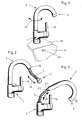
- the outlet fitting shown in Figure 1 is formed on a single-lever mixer valve which can be operated with one hand.
- an operating lever 15 is formed laterally in a housing 1, with which the mixing ratio of cold and hot water can be set in a known manner in a first degree of freedom and the total flow rate in a second degree of freedom.
- the housing 1 is held on a basin 6 of a washstand and / or sink on an approximately horizontally arranged dashboard 62 with a single-hole fastening.
- the inflow lines for cold and hot water are arranged below the valve bank 62, the mixed water generated in the single-lever mixer valve also being fed into the hose line 5 below the valve bank 62 (not shown in the drawing).
- the hose line is guided approximately coaxially through the housing 1 and is then received by a pipe guide 2, on the free end region 20 of which an outlet mouthpiece 3 is arranged.
- the pipe guide 2 is rotatably arranged on the housing 1 in the direction of the arrows 22, so that the outlet fitting in this position fulfills the function of a single-lever mixer valve with a swivel spout.
- the pipe guide 2 is bent in a U-shape over an angle of approximately 165 °, so that the water jet generated in the outlet mouthpiece 3 is directed into the basin 6 with the overflow opening 61.
- the flexible hose line 5 is under the washing and / or Dimensioned sink arranged so that the outlet mouthpiece 3 connected to the hose line 5 can be moved in the direction of arrow 23 as it can be seen in particular from Figure 2.
- the spout 3 as a pull-out Use hand shower or that from the spout 3 emerging water jet in any direction to steer.
- the pipe guide 2 is also held removable with a pin 21 in a receiving opening of the housing 1.
- the pipe guide 2 with the outlet mouthpiece 3 resting on the free end region 20 can be pulled out of the housing 1 in the direction of the arrow 24 and put back.
- Such a functional position of the outlet fitting is particularly suitable for filling tall vessels.
- the height of the outlet fitting can be considerably reduced in this functional position, which usually allows the window sash to be opened easily when the outlet fitting is installed in the area of a building window.
- a circumferential annular groove 211 is formed on the pin 21, which in the plug-in position surrounds a locking device or coupling arranged in the housing 1 (not shown in the drawing).
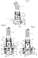
- the outlet mouthpiece 3 shown in Figures 1 to 3 is shown in Figure 4 on an enlarged scale.
- the hose line 5 is in this case connected with a union nut 51 to a neck 39 of the outlet mouthpiece 3 with a reduced diameter.
- the union nut 51 is conical on the outer jacket 511, so that problem-free return of the drawn-out spout 3 into the pipe guide 2 is possible and in the plug-in position a secure mounting and guidance of the spout 3 in the pipe guide 2 is ensured.
- the outlet mouthpiece 3 rests with a stop formation 30 on the end face of the free end region 20 of the pipe guide 2.
- a commercially available non-return valve 4 is arranged in the extension 39 downstream of the connection of the hose line 5. With the backflow preventer 4, it is prevented that in the event of a malfunction with a negative pressure in the supply water pipelines, especially when the outlet mouthpiece 3 is pulled out of the pipe guide 2, dirty water can be sucked back into the supply network in an impermissible manner.
- the outlet mouthpiece 3 is provided with a circumferential collar 31, which expediently has a slightly larger outer diameter than the pipe guide 2.
- the outer jacket of the collar 31 can be provided with corrugation, cording or other surface structure to increase the grip.
- an opening 381 is formed in the outlet mouthpiece 3 coaxially with the central axis 300 and is connected to an outlet opening 32.
- a commercially available water jet aerating nozzle by means of thread 320 is arranged as the outlet opening 32.
- FIG. 5 of the drawing shows another outlet mouthpiece 3, the connection of the hose line 5 and the arrangement of the backflow preventer 4 being designed in accordance with the embodiment according to FIG. 4.
- a series of outlet openings 33 for generating shower jets are formed concentrically with the central axis 300.
- the outlet opening 32 for the generation of a bundled water jet is arranged coaxially to the central axis 300.
- a switch 34 is formed downstream of the opening 381, by means of which the water supplied via the opening 381 can alternatively be fed to the outlet openings 33 for generating shower jets or to the outlet opening 32 for generating a bundled water jet.
- a radial slide 340 with a passage opening 341 transverse to the water flow direction is arranged as a changeover switch 34 in the outlet mouthpiece 3.
- the radial slide 340 is dimensioned in its length so that it protrudes radially from the outer surface of the outlet mouthpiece 3, so that the radial slide 340 can be displaced by the user by a certain distance transversely to the water flow direction.
- the passage opening 341 is dimensioned such that only the outlet opening 32 or the outlet opening 33 are supplied with water in the respective end position of the radial slide 340, whereby on the other hand it is ensured that a shut-off of the water outlet is avoided during the switching process, since otherwise impermissibly high pressure surges can occur in the hose line 5.
- the radial slide valve 340 is designed as a flat slide valve and is sealed with seals 37 on the outlet side of the opening 381 and in the region of the inflow channels to the openings 32 and 33.
- the outlet mouthpiece 3 is provided with a housing which consists of an upstream housing part 38 and a downstream housing part 35.
- the two housing parts 35 and 38 can advantageously be produced from plastic by the injection molding process, the two housing parts 35, 38 being welded with the aid of a welding sleeve 351 after the radial slide 340 and the seals 37 have been introduced.
- the radial slide valve made of flat material can be used 340 also made of rod material with a circular Cross section be made, then appropriate instead of the passage opening 341 in the flow area a constriction is formed on the outer jacket.
- FIG. 6 shows an embodiment modified from FIG. 5 the outlet mouthpiece 3 shown.
- the switch 34 is designed as a rotary valve 345.
- housing part 38 arranged upstream is here the opening 381 is formed eccentrically to the central axis 300, through which the incoming water to the rotary valve 345 is forwarded.
- the housing part 35 is formed of rotary slide valve 345, the housing part 35 with an inseparable snap connection 36 rotatable with the upstream Housing part 38 is connected.
- the two housing parts 35 and 38 and the opening 381 are through seals 37 secured so that depending on the rotational position of the two housing parts 35, 38 to one another, optionally the outlet opening 32 or the outlet openings 33 the inflowing water is supplied.
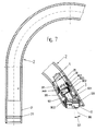
- FIG. 7 shows a further exemplary embodiment of the pipe guide 2 with the outlet mouthpiece 3.
- the pin 21 also has an outer diameter corresponding to the pipe guide 2.
- the annular groove 211 is formed with two 45 ° side chamfers, in which the coupling or locking device (not shown in the drawing) fits in the plug position, so that unintentional removal of the pipe guide 2 is excluded.
- the pipe guide 2 is provided with a U-bend of 150 ° in this version.
- the outlet mouthpiece 3 is arranged in its plug-in position, which has a projection 301 on the stop formation 30, with which it surrounds the non-rotatable mounting in the plug-in position in a corresponding recess on the end face of the end region 20 of the pipe guide 2.
- the outlet mouthpiece 3 consists essentially of an inner water-carrying part 302 and an outer sleeve body 303, the sleeve body 303 also serving as a gripping surface for the user and being provided with a reduced-diameter attachment, which in the plug-in position is provided with a corresponding diameter Bore in the end region 20 is added.
- a coupling 3021 for connecting the hose line 5 is provided on the inner part 302.
- a flow channel 3022 is formed in the part 302, which opens into the outlet opening 32 arranged at an angle 321 of approximately 30 °, so that in the plugged-in position the emerging water jet is emitted into the basin 6 parallel to the pin 21.
- the sleeve body 303 is essentially at a distance from the inner water-carrying part 302, so that undesired heating of the sleeve body 303 is largely excluded when hot water escapes.
- the sleeve body 303 is in this case secured axially, in particular by means of an O-ring 3031.
- the rotation of the sleeve body 303 to the part 302 takes place with a nose 3023 protruding radially on the part 302, which lugs into an axial slot 3032 of the sleeve body 303.
- the sleeve body 303 secures the locking fingers of the coupling 3021 with an inner collar 3033, so that it is not possible to release the coupling 3021 in the assembled position.
Landscapes
- Health & Medical Sciences (AREA)
- Life Sciences & Earth Sciences (AREA)
- Engineering & Computer Science (AREA)
- Hydrology & Water Resources (AREA)
- Public Health (AREA)
- Water Supply & Treatment (AREA)
- Domestic Plumbing Installations (AREA)
- Quick-Acting Or Multi-Walled Pipe Joints (AREA)
- Confectionery (AREA)
- Nozzles (AREA)
- Mechanical Coupling Of Light Guides (AREA)
- Dry Shavers And Clippers (AREA)
- Pipe Accessories (AREA)
- Joints Allowing Movement (AREA)
- Control Of Eletrric Generators (AREA)
- Control Of Motors That Do Not Use Commutators (AREA)
- Stabilization Of Oscillater, Synchronisation, Frequency Synthesizers (AREA)
- Sanitary Device For Flush Toilet (AREA)
Applications Claiming Priority (2)
| Application Number | Priority Date | Filing Date | Title |
|---|---|---|---|
| DE19527232A DE19527232A1 (de) | 1995-07-26 | 1995-07-26 | Auslaufarmatur |
| DE19527232 | 1995-07-26 |
Publications (2)
| Publication Number | Publication Date |
|---|---|
| EP0756038A1 EP0756038A1 (de) | 1997-01-29 |
| EP0756038B1 true EP0756038B1 (de) | 2000-03-01 |
Family
ID=7767794
Family Applications (1)
| Application Number | Title | Priority Date | Filing Date |
|---|---|---|---|
| EP96110931A Expired - Lifetime EP0756038B1 (de) | 1995-07-26 | 1996-07-06 | Auslaufarmatur |
Country Status (7)
| Country | Link |
|---|---|
| US (1) | US5758690A (es) |
| EP (1) | EP0756038B1 (es) |
| JP (1) | JPH0941439A (es) |
| AT (1) | ATE190101T1 (es) |
| DE (2) | DE19527232A1 (es) |
| DK (1) | DK0756038T3 (es) |
| ES (2) | ES2145954T3 (es) |
Cited By (1)
| Publication number | Priority date | Publication date | Assignee | Title |
|---|---|---|---|---|
| EP1201836A2 (de) | 2000-10-24 | 2002-05-02 | Hansa Metallwerke Ag | Sanitäre Auslaufarmatur |
Families Citing this family (94)
| Publication number | Priority date | Publication date | Assignee | Title |
|---|---|---|---|---|
| NL1002478C2 (nl) * | 1996-02-28 | 1997-08-29 | Peteri B V | Heetwaterkraan. |
| DE19803554A1 (de) | 1998-01-30 | 1999-08-05 | Grohe Armaturen Friedrich | Wasserausflußarmatur |
| US6070614A (en) * | 1999-03-08 | 2000-06-06 | Moen Incorporated | Faucet mounting system with improved bearing support |
| US6296011B1 (en) | 1999-04-14 | 2001-10-02 | Kohler Co. | Fluid valve |
| USD443337S1 (en) | 2000-02-17 | 2001-06-05 | Emhart Inc. | Faucet with pull-out spout |
| USD438934S1 (en) | 2000-02-17 | 2001-03-13 | Emhart Inc. | Faucet with pull-out spout |
| USD438935S1 (en) | 2000-02-17 | 2001-03-13 | Emhart Inc. | Faucet with pull-out spout |
| USD438286S1 (en) | 2000-02-17 | 2001-02-27 | Emhart Inc. | Faucet |
| USD441836S1 (en) | 2000-02-17 | 2001-05-08 | Emhart Inc. | Faucet with pull-out spout |
| USD438287S1 (en) | 2000-02-17 | 2001-02-27 | Emhart Inc. | Faucet with pull-out spout |
| USD438599S1 (en) | 2000-02-17 | 2001-03-06 | Emhart Inc. | Faucet with pull-out spout |
| USD438289S1 (en) | 2000-03-22 | 2001-02-27 | Emhart Inc. | Faucet with pullout spout |
| USD438288S1 (en) | 2000-03-22 | 2001-02-27 | Emhart Inc. | Faucet |
| US6381774B1 (en) | 2000-07-18 | 2002-05-07 | Resources Conservation, Inc. | Retractable hose for faucet |
| US6381770B1 (en) | 2001-02-23 | 2002-05-07 | Kevin Norman Raisch | Extendable bathtub spout |
| ES2226506B1 (es) * | 2001-02-23 | 2006-06-01 | Roberto Ladron Jimenez | Caño para grifo con disposicion de salidas separadas de agua filtrada y de uso corriente, movil y extraible. |
| JP3947364B2 (ja) * | 2001-03-09 | 2007-07-18 | 株式会社三栄水栓製作所 | 切替機構付シャワヘッドを備えたスプレー混合栓 |
| US6659124B2 (en) | 2001-11-08 | 2003-12-09 | Moen Incorporated | Side spray mounting with collapsible insert |
| US6738995B1 (en) | 2001-12-14 | 2004-05-25 | Reginal Eugene Payne | Bucket filler |
| GB0201604D0 (en) * | 2002-01-24 | 2002-03-13 | Hornbeam Ivy Ltd | Tap |
| USD470224S1 (en) | 2002-01-29 | 2003-02-11 | Emhart Llc | Faucet |
| USD477052S1 (en) | 2002-03-04 | 2003-07-08 | Hansgrohe Ag | Sanitary fitting, especially kitchen faucet |
| ITMN20020013A1 (it) * | 2002-04-04 | 2003-10-06 | Amfag Spa | Doccia estraibile da cucina |
| ITMN20020014A1 (it) * | 2002-04-04 | 2003-10-06 | Amfag Spa | Doccia estraibile da cucina |
| US6757921B2 (en) * | 2002-07-16 | 2004-07-06 | Kohler Co. | Pull-out faucet |
| US6964595B2 (en) * | 2002-12-20 | 2005-11-15 | Mattel, Inc | Child's infant-care play center |
| US6938837B2 (en) * | 2003-01-23 | 2005-09-06 | Masco Corporation Of Indiana | Faucet spray head assembly |
| US6915816B2 (en) * | 2003-03-12 | 2005-07-12 | Masco Corporation Of Indiana | Faucet spray head hose guide and retraction mechanism |
| US7690395B2 (en) | 2004-01-12 | 2010-04-06 | Masco Corporation Of Indiana | Multi-mode hands free automatic faucet |
| US8939429B2 (en) | 2004-01-12 | 2015-01-27 | Masco Corporation Of Indiana | Spout assembly for an electronic faucet |
| US7997301B2 (en) | 2004-01-12 | 2011-08-16 | Masco Corporation Of Indiana | Spout assembly for an electronic faucet |
| US7150293B2 (en) * | 2004-01-12 | 2006-12-19 | Masco Corporation Of Indiana | Multi-mode hands free automatic faucet |
| US20060207670A1 (en) * | 2005-03-16 | 2006-09-21 | Mike Peters | Faucet extension which makes it easier to reach the running water. |
| US7909061B2 (en) | 2005-06-17 | 2011-03-22 | Masco Corporation Of Indiana | Magnetic coupling for sprayheads |
| US7753079B2 (en) | 2005-06-17 | 2010-07-13 | Masco Corporation Of Indiana | Magnetic coupling for sprayheads |
| US7162782B1 (en) | 2005-07-07 | 2007-01-16 | Masco Corporation Of Indiana | Spring retainer and installation aid |
| US7406980B2 (en) * | 2005-08-29 | 2008-08-05 | Masco Corporation Of Indiana | Waterway connection |
| US20070089794A1 (en) * | 2005-10-22 | 2007-04-26 | Chen Jeffrey M | Water faucet with dispenser angle adjustment mechanism |
| US7415991B2 (en) * | 2005-12-20 | 2008-08-26 | Masco Corporation Of Indiana | Faucet spout with water isolating couplings |
| US20070145319A1 (en) * | 2005-12-28 | 2007-06-28 | Victor Hoernig | Flow control device |
| ITMI20060357A1 (it) * | 2006-02-28 | 2007-09-01 | Fabrizio Nobili | Doccetta per lavello con variazione del getto di erogazione e regolazione della portata |
| US20070235091A1 (en) * | 2006-04-06 | 2007-10-11 | Yoav Granot | Water tap assembly having a pull-out water-discharge head |
| US8991425B2 (en) | 2006-05-26 | 2015-03-31 | Delta Faucet Company | Waterway assembly including an overmolded support plate |
| US7766043B2 (en) * | 2006-05-26 | 2010-08-03 | Masco Corporation Of Indiana | Faucet including a molded waterway assembly |
| DE102006041945A1 (de) * | 2006-08-29 | 2008-03-06 | Hansgrohe Ag | Brauseanordnung |
| US7909269B2 (en) | 2006-09-19 | 2011-03-22 | Kohler Co. | Faucet spray control assembly |
| US9243392B2 (en) | 2006-12-19 | 2016-01-26 | Delta Faucet Company | Resistive coupling for an automatic faucet |
| US7717133B2 (en) * | 2007-01-31 | 2010-05-18 | Masco Corporation Of Indiana | Spout tip attachment |
| US7748409B2 (en) * | 2007-01-31 | 2010-07-06 | Masco Corporation Of Indiana | Overmold interface for fluid carrying system |
| US20080178957A1 (en) * | 2007-01-31 | 2008-07-31 | Masco Corporation Of Indiana | Tube assembly |
| WO2008094651A1 (en) | 2007-01-31 | 2008-08-07 | Masco Corporation Of Indiana | Capacitive sensing apparatus and method for faucets |
| US7806141B2 (en) | 2007-01-31 | 2010-10-05 | Masco Corporation Of Indiana | Mixing valve including a molded waterway assembly |
| CA2675417C (en) | 2007-03-28 | 2015-10-13 | Masco Corporation Of Indiana | Improved capacitive touch sensor |
| EP2574701A1 (en) | 2007-12-11 | 2013-04-03 | Masco Corporation Of Indiana | Electrically controlled Faucet |
| DK2229487T3 (da) | 2007-12-15 | 2020-02-24 | Grohe Ag | Varmtvandshane med isoleret udløb |
| US8430345B2 (en) * | 2008-02-12 | 2013-04-30 | Kohler Co. | Swivel spout assembly |
| WO2009126887A1 (en) | 2008-04-10 | 2009-10-15 | Masco Corporation Of Indiana | Molded waterway for a two handle faucet |
| US8695625B2 (en) | 2008-06-25 | 2014-04-15 | Masco Corporation Of Indiana | Centerset faucet with mountable spout |
| US8104512B2 (en) | 2008-09-25 | 2012-01-31 | Masco Corporation Of Indiana | Spout tip retention method |
| US8863769B2 (en) * | 2008-10-28 | 2014-10-21 | Kohler Co. | Sprayer seating assembly |
| US8376248B2 (en) * | 2008-11-25 | 2013-02-19 | As Ip Holdco, L.L.C. | Faucet having pull-out spray handle |
| US8186375B2 (en) * | 2009-01-15 | 2012-05-29 | Kohler Co. | Retainer assembly for swivel spout |
| JP5607887B2 (ja) * | 2009-03-12 | 2014-10-15 | トーヨーキッチンアンドリビング株式会社 | 厨房設備の水栓装置 |
| NZ581572A (en) * | 2009-12-02 | 2010-02-26 | Taiyo Christian Weber | Rotatable tube sealed on spigot via washer, with central and end apertures providing selectable exit flow via tube rotation |
| US8561626B2 (en) | 2010-04-20 | 2013-10-22 | Masco Corporation Of Indiana | Capacitive sensing system and method for operating a faucet |
| US8776817B2 (en) | 2010-04-20 | 2014-07-15 | Masco Corporation Of Indiana | Electronic faucet with a capacitive sensing system and a method therefor |
| US8739826B2 (en) | 2011-03-11 | 2014-06-03 | Masco Corporation Of Indiana | Centerset faucet body and method of making same |
| ITMI20111255A1 (it) * | 2011-07-06 | 2013-01-07 | Neve Rubinetterie S R L | Struttura di rubinetto, particolarmente per gruppo vasca a pavimento . |
| US8931500B2 (en) | 2012-02-17 | 2015-01-13 | Masco Corporation Of Indiana | Two handle centerset faucet |
| US9181685B2 (en) | 2012-07-27 | 2015-11-10 | Kohler Co. | Magnetic docking faucet |
| US9284723B2 (en) | 2012-07-27 | 2016-03-15 | Kohler Co. | Magnetic docking faucet |
| US9435107B2 (en) | 2012-09-07 | 2016-09-06 | Kohler Co. | Shape memory faucet |
| USD698902S1 (en) | 2012-09-13 | 2014-02-04 | Moen Incorporated | Faucet hub |
| DE202013002189U1 (de) | 2013-03-08 | 2014-06-11 | Neoperl Gmbh | Sanitäres Einbauteil, Einbauteil-Anordnung und Sanitärarmatur |
| DE102013003925A1 (de) * | 2013-03-08 | 2014-09-11 | Neoperl Gmbh | Sanitäres Einbauteil, Einbauteil-Anordnung und Sanitärarmatur |
| CN104565477B (zh) * | 2013-10-29 | 2019-02-05 | 成霖企业股份有限公司 | 拉出式水龙头的供水软管定位构造 |
| USD717914S1 (en) | 2013-11-27 | 2014-11-18 | Price Pfister, Inc. | Faucet |
| USD717400S1 (en) | 2013-11-26 | 2014-11-11 | Price Pfister, Inc. | Faucet |
| US9657874B2 (en) | 2014-04-25 | 2017-05-23 | Kohler Co. | Plumbing fitting adapter |
| CN203927007U (zh) * | 2014-06-20 | 2014-11-05 | 宋在俊 | 智能控制水龙头 |
| AU2015351375A1 (en) * | 2014-11-21 | 2017-06-08 | Lixil Corporation | Automatic water faucet |
| US11085175B2 (en) | 2015-01-26 | 2021-08-10 | Delta Faucet Company | Pulldown kitchen faucet with spring spout |
| NL2016083B1 (nl) * | 2016-01-11 | 2017-07-24 | Henri Peteri Beheer Bv | Mengkraan voor het afgeven van water. |
| USD867850S1 (en) | 2017-11-20 | 2019-11-26 | As America, Inc. | Faucet dial |
| USD855154S1 (en) * | 2017-11-20 | 2019-07-30 | As America, Inc. | Faucet |
| CN110529683A (zh) * | 2018-05-24 | 2019-12-03 | 厦门松霖科技股份有限公司 | 升降机构、卫浴装置的升降机构和可调节高度的出水装置 |
| JP7171308B2 (ja) * | 2018-08-10 | 2022-11-15 | 株式会社Lixil | 吐水装置及び洗面台 |
| US11091871B2 (en) | 2019-02-19 | 2021-08-17 | Haier Us Appliance Solutions, Inc. | Pivoted faucet in a lid of a top load washing machine |
| DE102019210111B4 (de) * | 2019-07-09 | 2021-05-20 | Hansgrohe Se | Sanitäre Auslaufarmatur mit Auslaufrohr |
| US12540463B2 (en) * | 2021-07-19 | 2026-02-03 | Delta Faucet Company | Soap dispenser in a kitchen faucet wand |
| CA3221537A1 (en) * | 2022-12-06 | 2024-06-06 | Assa Abloy Americas Residential Inc. | Faucet with flow conditioner coupling |
| CN116146750B (zh) * | 2022-12-13 | 2025-09-16 | 洛基特水暖厨卫系统(广东)有限公司 | 一种带光感雾化功能龙头 |
| CN116292991A (zh) * | 2023-02-07 | 2023-06-23 | 厦门方特卫浴有限公司 | 一种多功能电子龙头 |
| US20250354635A1 (en) * | 2024-05-16 | 2025-11-20 | Joshua P. Harshmann | Nestled hose |
Family Cites Families (17)
| Publication number | Priority date | Publication date | Assignee | Title |
|---|---|---|---|---|
| US824454A (en) * | 1904-12-02 | 1906-06-26 | William Vanderman | Bath-tub. |
| US865355A (en) * | 1907-04-19 | 1907-09-10 | Irving Callmann | Spraying device. |
| US2971520A (en) * | 1956-06-18 | 1961-02-14 | Waste King Corp | Rinsing apparatus for dishes |
| DE1247972B (de) * | 1964-04-16 | 1967-08-17 | Schmiedl Gustav | Schwenkauslauf-Abdichtung fuer Armaturen |
| DE1956579A1 (de) * | 1969-11-11 | 1971-05-19 | Hansa Metallwerke Ag | Wasserzulauf fuer Sitzwaschbecken oder sonstige sanitaere Becken |
| US3722798A (en) * | 1970-10-29 | 1973-03-27 | Bletcher R | Combined aerator spray assembly |
| DE2161762A1 (de) * | 1971-12-13 | 1973-06-14 | Laubrunn | Befestigungsvorrichtung eines schwenkbaren gussauslaufes an einer einlochbatterie |
| DE3344614A1 (de) * | 1983-12-09 | 1985-06-20 | Mannesmann + Keppel GmbH & Co KG, 8036 Herrsching | Adapter zum verbinden einer wasserauslaufarmatur mit einem wasserauslauf von ungenormtem anschlussquerschnitt |
| DE8812525U1 (de) * | 1988-10-05 | 1990-02-08 | Hans Grohe Gmbh & Co Kg, 7622 Schiltach | Verstellbarer Wasserauslauf |
| DE3902588C1 (es) * | 1989-01-28 | 1990-03-15 | Ideal-Standard Gmbh, 5300 Bonn, De | |
| DE3908009C2 (de) * | 1989-03-11 | 1996-09-19 | Grohe Kg Hans | Sanitärventil |
| US4964573A (en) * | 1989-06-21 | 1990-10-23 | Pinchas Lipski | Showerhead adaptor means |
| CH681731A5 (es) * | 1990-01-26 | 1993-05-14 | Kugler Fonderie Robinetterie | |
| AU632201B2 (en) * | 1990-02-05 | 1992-12-17 | Friedrich Grohe Ag | Water tap fitting with reverse-suction prevention |
| US5073991A (en) * | 1991-01-16 | 1991-12-24 | 501 Masco Industries, Inc. | Pull-out lavatory |
| DE4116927A1 (de) * | 1991-05-24 | 1992-11-26 | Grohe Armaturen Friedrich | Brause |
| US5575424A (en) * | 1994-10-20 | 1996-11-19 | Kohler Co. | Vacuum breaker for faucets |
-
1995
- 1995-07-26 DE DE19527232A patent/DE19527232A1/de not_active Withdrawn
-
1996
- 1996-07-06 DK DK96110931T patent/DK0756038T3/da active
- 1996-07-06 ES ES96110931T patent/ES2145954T3/es not_active Expired - Lifetime
- 1996-07-06 EP EP96110931A patent/EP0756038B1/de not_active Expired - Lifetime
- 1996-07-06 AT AT96110931T patent/ATE190101T1/de not_active IP Right Cessation
- 1996-07-06 DE DE59604526T patent/DE59604526D1/de not_active Expired - Lifetime
- 1996-07-09 JP JP8179276A patent/JPH0941439A/ja not_active Abandoned
- 1996-07-09 US US08/677,393 patent/US5758690A/en not_active Expired - Fee Related
- 1996-07-25 ES ES09602030U patent/ES1034770Y/es not_active Expired - Fee Related
Cited By (2)
| Publication number | Priority date | Publication date | Assignee | Title |
|---|---|---|---|---|
| EP1201836A2 (de) | 2000-10-24 | 2002-05-02 | Hansa Metallwerke Ag | Sanitäre Auslaufarmatur |
| DE10052661C1 (de) * | 2000-10-24 | 2002-11-07 | Hansa Metallwerke Ag | Sanitäre Auslaufarmatur |
Also Published As
| Publication number | Publication date |
|---|---|
| DK0756038T3 (da) | 2000-07-24 |
| DE59604526D1 (de) | 2000-04-06 |
| EP0756038A1 (de) | 1997-01-29 |
| JPH0941439A (ja) | 1997-02-10 |
| ES2145954T3 (es) | 2000-07-16 |
| DE19527232A1 (de) | 1997-01-30 |
| US5758690A (en) | 1998-06-02 |
| ES1034770U (es) | 1997-02-01 |
| ATE190101T1 (de) | 2000-03-15 |
| ES1034770Y (es) | 1997-07-01 |
Similar Documents
| Publication | Publication Date | Title |
|---|---|---|
| EP0756038B1 (de) | Auslaufarmatur | |
| EP0681127B2 (de) | Wasserarmatur | |
| DE19803554A1 (de) | Wasserausflußarmatur | |
| DE69408058T2 (de) | Umstellventilkartusche | |
| EP0432553B1 (de) | Sanitäre Armatur | |
| EP1663504B1 (de) | Reinigungslanze | |
| EP1738036B1 (de) | Luftbeimischer für eine wasserarmatur | |
| DE3603503A1 (de) | Mischbatterie mit schlauchbrausenauslauf | |
| EP0724042A1 (de) | Auslaufarmatur mit Befestigungseinrichtung | |
| DE102005003404B3 (de) | Sanitäre Auslaufeinheit | |
| DE10023723A1 (de) | Wasserzapfarmatur | |
| EP0942104B1 (de) | Wasserarmatur | |
| EP1103749B1 (de) | Wasserarmatur | |
| EP1216756A2 (de) | Handbrause | |
| DE4421387B4 (de) | Einlochmischbatterie | |
| EP0441151A1 (de) | Wasserzapfarmatur mit Rücksaugsicherung | |
| EP3591128A1 (de) | Armatureneinheit mit axialer ausrichtung von bedienelementen | |
| DE2653754A1 (de) | Wannfuell- und brausebatterie | |
| EP1061299A2 (de) | Umschaltventil | |
| EP1798348B1 (de) | Mischbatterie | |
| DE19756971A1 (de) | Einhebelmischer | |
| DE3120210A1 (de) | Wasserzapfarmatur | |
| DE19649004A1 (de) | Brausevorrichtung | |
| EP3556951B1 (de) | Sanitärventilblock | |
| DE3135860A1 (de) | Auslaufarmatur |
Legal Events
| Date | Code | Title | Description |
|---|---|---|---|
| PUAI | Public reference made under article 153(3) epc to a published international application that has entered the european phase |
Free format text: ORIGINAL CODE: 0009012 |
|
| AK | Designated contracting states |
Kind code of ref document: A1 Designated state(s): AT CH DE DK ES FR GB IT LI NL SE |
|
| 17P | Request for examination filed |
Effective date: 19970426 |
|
| 17Q | First examination report despatched |
Effective date: 19970707 |
|
| GRAG | Despatch of communication of intention to grant |
Free format text: ORIGINAL CODE: EPIDOS AGRA |
|
| GRAG | Despatch of communication of intention to grant |
Free format text: ORIGINAL CODE: EPIDOS AGRA |
|
| GRAH | Despatch of communication of intention to grant a patent |
Free format text: ORIGINAL CODE: EPIDOS IGRA |
|
| GRAH | Despatch of communication of intention to grant a patent |
Free format text: ORIGINAL CODE: EPIDOS IGRA |
|
| GRAA | (expected) grant |
Free format text: ORIGINAL CODE: 0009210 |
|
| AK | Designated contracting states |
Kind code of ref document: B1 Designated state(s): AT CH DE DK ES FR GB IT LI NL SE |
|
| REF | Corresponds to: |
Ref document number: 190101 Country of ref document: AT Date of ref document: 20000315 Kind code of ref document: T |
|
| REG | Reference to a national code |
Ref country code: CH Ref legal event code: EP |
|
| REF | Corresponds to: |
Ref document number: 59604526 Country of ref document: DE Date of ref document: 20000406 |
|
| REG | Reference to a national code |
Ref country code: CH Ref legal event code: NV Representative=s name: BOVARD AG PATENTANWAELTE |
|
| ITF | It: translation for a ep patent filed | ||
| ET | Fr: translation filed | ||
| GBT | Gb: translation of ep patent filed (gb section 77(6)(a)/1977) |
Effective date: 20000517 |
|
| RAP2 | Party data changed (patent owner data changed or rights of a patent transferred) |
Owner name: FRIEDRICH GROHE AG & CO. KG |
|
| REG | Reference to a national code |
Ref country code: ES Ref legal event code: FG2A Ref document number: 2145954 Country of ref document: ES Kind code of ref document: T3 |
|
| REG | Reference to a national code |
Ref country code: DK Ref legal event code: T3 |
|
| NLT1 | Nl: modifications of names registered in virtue of documents presented to the patent office pursuant to art. 16 a, paragraph 1 |
Owner name: FRIEDRICH GROHE AG & CO. KG |
|
| NLT2 | Nl: modifications (of names), taken from the european patent patent bulletin |
Owner name: FRIEDRICH GROHE AG & CO. KG |
|
| REG | Reference to a national code |
Ref country code: CH Ref legal event code: PFA Free format text: FRIEDRICH GROHE AKTIENGESELLSCHAFT TRANSFER- FRIEDRICH GROHE AG & CO. KG |
|
| REG | Reference to a national code |
Ref country code: FR Ref legal event code: CJ |
|
| PLBE | No opposition filed within time limit |
Free format text: ORIGINAL CODE: 0009261 |
|
| STAA | Information on the status of an ep patent application or granted ep patent |
Free format text: STATUS: NO OPPOSITION FILED WITHIN TIME LIMIT |
|
| 26N | No opposition filed | ||
| REG | Reference to a national code |
Ref country code: GB Ref legal event code: IF02 |
|
| PGFP | Annual fee paid to national office [announced via postgrant information from national office to epo] |
Ref country code: SE Payment date: 20030714 Year of fee payment: 8 |
|
| PGFP | Annual fee paid to national office [announced via postgrant information from national office to epo] |
Ref country code: DK Payment date: 20030718 Year of fee payment: 8 |
|
| PGFP | Annual fee paid to national office [announced via postgrant information from national office to epo] |
Ref country code: GB Payment date: 20040630 Year of fee payment: 9 |
|
| PG25 | Lapsed in a contracting state [announced via postgrant information from national office to epo] |
Ref country code: SE Free format text: LAPSE BECAUSE OF NON-PAYMENT OF DUE FEES Effective date: 20040707 |
|
| PGFP | Annual fee paid to national office [announced via postgrant information from national office to epo] |
Ref country code: CH Payment date: 20040708 Year of fee payment: 9 |
|
| PGFP | Annual fee paid to national office [announced via postgrant information from national office to epo] |
Ref country code: AT Payment date: 20040727 Year of fee payment: 9 |
|
| PG25 | Lapsed in a contracting state [announced via postgrant information from national office to epo] |
Ref country code: DK Free format text: LAPSE BECAUSE OF NON-PAYMENT OF DUE FEES Effective date: 20040802 |
|
| EUG | Se: european patent has lapsed | ||
| REG | Reference to a national code |
Ref country code: DK Ref legal event code: EBP |
|
| PGFP | Annual fee paid to national office [announced via postgrant information from national office to epo] |
Ref country code: NL Payment date: 20050630 Year of fee payment: 10 |
|
| PG25 | Lapsed in a contracting state [announced via postgrant information from national office to epo] |
Ref country code: GB Free format text: LAPSE BECAUSE OF NON-PAYMENT OF DUE FEES Effective date: 20050706 Ref country code: AT Free format text: LAPSE BECAUSE OF NON-PAYMENT OF DUE FEES Effective date: 20050706 |
|
| PGFP | Annual fee paid to national office [announced via postgrant information from national office to epo] |
Ref country code: FR Payment date: 20050728 Year of fee payment: 10 |
|
| PG25 | Lapsed in a contracting state [announced via postgrant information from national office to epo] |
Ref country code: LI Free format text: LAPSE BECAUSE OF NON-PAYMENT OF DUE FEES Effective date: 20050731 Ref country code: CH Free format text: LAPSE BECAUSE OF NON-PAYMENT OF DUE FEES Effective date: 20050731 |
|
| PGFP | Annual fee paid to national office [announced via postgrant information from national office to epo] |
Ref country code: ES Payment date: 20050818 Year of fee payment: 10 |
|
| REG | Reference to a national code |
Ref country code: CH Ref legal event code: PL |
|
| GBPC | Gb: european patent ceased through non-payment of renewal fee |
Effective date: 20050706 |
|
| PGFP | Annual fee paid to national office [announced via postgrant information from national office to epo] |
Ref country code: IT Payment date: 20060731 Year of fee payment: 11 |
|
| PG25 | Lapsed in a contracting state [announced via postgrant information from national office to epo] |
Ref country code: NL Free format text: LAPSE BECAUSE OF NON-PAYMENT OF DUE FEES Effective date: 20070201 |
|
| NLV4 | Nl: lapsed or anulled due to non-payment of the annual fee |
Effective date: 20070201 |
|
| REG | Reference to a national code |
Ref country code: FR Ref legal event code: ST Effective date: 20070330 |
|
| REG | Reference to a national code |
Ref country code: ES Ref legal event code: FD2A Effective date: 20060707 |
|
| PG25 | Lapsed in a contracting state [announced via postgrant information from national office to epo] |
Ref country code: ES Free format text: LAPSE BECAUSE OF NON-PAYMENT OF DUE FEES Effective date: 20060707 |
|
| PG25 | Lapsed in a contracting state [announced via postgrant information from national office to epo] |
Ref country code: FR Free format text: LAPSE BECAUSE OF NON-PAYMENT OF DUE FEES Effective date: 20060731 |
|
| PG25 | Lapsed in a contracting state [announced via postgrant information from national office to epo] |
Ref country code: IT Free format text: LAPSE BECAUSE OF NON-PAYMENT OF DUE FEES Effective date: 20070706 |
|
| PGFP | Annual fee paid to national office [announced via postgrant information from national office to epo] |
Ref country code: DE Payment date: 20150721 Year of fee payment: 20 |
|
| REG | Reference to a national code |
Ref country code: DE Ref legal event code: R071 Ref document number: 59604526 Country of ref document: DE |