EP0755725B1 - Anordnung zum Trennen nach der Form - Google Patents
Anordnung zum Trennen nach der Form Download PDFInfo
- Publication number
- EP0755725B1 EP0755725B1 EP96104082A EP96104082A EP0755725B1 EP 0755725 B1 EP0755725 B1 EP 0755725B1 EP 96104082 A EP96104082 A EP 96104082A EP 96104082 A EP96104082 A EP 96104082A EP 0755725 B1 EP0755725 B1 EP 0755725B1
- Authority
- EP
- European Patent Office
- Prior art keywords
- sieve
- fraction
- solid matter
- arrangement
- sieve bottom
- Prior art date
- Legal status (The legal status is an assumption and is not a legal conclusion. Google has not performed a legal analysis and makes no representation as to the accuracy of the status listed.)
- Expired - Lifetime
Links
- 239000007787 solid Substances 0.000 claims abstract description 13
- 239000002245 particle Substances 0.000 claims abstract description 4
- 239000000203 mixture Substances 0.000 claims description 13
- 238000012216 screening Methods 0.000 claims description 4
- 239000000725 suspension Substances 0.000 claims description 4
- 238000007873 sieving Methods 0.000 claims description 2
- 239000010419 fine particle Substances 0.000 claims 1
- 239000008247 solid mixture Substances 0.000 description 13
- 239000004033 plastic Substances 0.000 description 6
- 238000000926 separation method Methods 0.000 description 5
- 239000012634 fragment Substances 0.000 description 4
- 239000000463 material Substances 0.000 description 4
- 239000002775 capsule Substances 0.000 description 3
- 238000011156 evaluation Methods 0.000 description 3
- 229910052500 inorganic mineral Inorganic materials 0.000 description 3
- 239000011707 mineral Substances 0.000 description 3
- 229910000831 Steel Inorganic materials 0.000 description 2
- 239000010959 steel Substances 0.000 description 2
- 239000002023 wood Substances 0.000 description 2
- 206010010774 Constipation Diseases 0.000 description 1
- 239000004566 building material Substances 0.000 description 1
- 239000007795 chemical reaction product Substances 0.000 description 1
- 238000010276 construction Methods 0.000 description 1
- 239000008187 granular material Substances 0.000 description 1
- 239000006148 magnetic separator Substances 0.000 description 1
- 238000000034 method Methods 0.000 description 1
- 239000000047 product Substances 0.000 description 1
- 239000000126 substance Substances 0.000 description 1
- 238000011144 upstream manufacturing Methods 0.000 description 1
- 239000002699 waste material Substances 0.000 description 1
Images

Classifications
-
- B—PERFORMING OPERATIONS; TRANSPORTING
- B07—SEPARATING SOLIDS FROM SOLIDS; SORTING
- B07B—SEPARATING SOLIDS FROM SOLIDS BY SIEVING, SCREENING, SIFTING OR BY USING GAS CURRENTS; SEPARATING BY OTHER DRY METHODS APPLICABLE TO BULK MATERIAL, e.g. LOOSE ARTICLES FIT TO BE HANDLED LIKE BULK MATERIAL
- B07B1/00—Sieving, screening, sifting, or sorting solid materials using networks, gratings, grids, or the like
- B07B1/46—Constructional details of screens in general; Cleaning or heating of screens
-
- B—PERFORMING OPERATIONS; TRANSPORTING
- B03—SEPARATION OF SOLID MATERIALS USING LIQUIDS OR USING PNEUMATIC TABLES OR JIGS; MAGNETIC OR ELECTROSTATIC SEPARATION OF SOLID MATERIALS FROM SOLID MATERIALS OR FLUIDS; SEPARATION BY HIGH-VOLTAGE ELECTRIC FIELDS
- B03B—SEPARATING SOLID MATERIALS USING LIQUIDS OR USING PNEUMATIC TABLES OR JIGS
- B03B9/00—General arrangement of separating plant, e.g. flow sheets
- B03B9/06—General arrangement of separating plant, e.g. flow sheets specially adapted for refuse
- B03B9/061—General arrangement of separating plant, e.g. flow sheets specially adapted for refuse the refuse being industrial
- B03B9/065—General arrangement of separating plant, e.g. flow sheets specially adapted for refuse the refuse being industrial the refuse being building rubble
-
- B—PERFORMING OPERATIONS; TRANSPORTING
- B07—SEPARATING SOLIDS FROM SOLIDS; SORTING
- B07B—SEPARATING SOLIDS FROM SOLIDS BY SIEVING, SCREENING, SIFTING OR BY USING GAS CURRENTS; SEPARATING BY OTHER DRY METHODS APPLICABLE TO BULK MATERIAL, e.g. LOOSE ARTICLES FIT TO BE HANDLED LIKE BULK MATERIAL
- B07B13/00—Grading or sorting solid materials by dry methods, not otherwise provided for; Sorting articles otherwise than by indirectly controlled devices
- B07B13/003—Separation of articles by differences in their geometrical form or by difference in their physical properties, e.g. elasticity, compressibility, hardness
-
- B—PERFORMING OPERATIONS; TRANSPORTING
- B07—SEPARATING SOLIDS FROM SOLIDS; SORTING
- B07B—SEPARATING SOLIDS FROM SOLIDS BY SIEVING, SCREENING, SIFTING OR BY USING GAS CURRENTS; SEPARATING BY OTHER DRY METHODS APPLICABLE TO BULK MATERIAL, e.g. LOOSE ARTICLES FIT TO BE HANDLED LIKE BULK MATERIAL
- B07B13/00—Grading or sorting solid materials by dry methods, not otherwise provided for; Sorting articles otherwise than by indirectly controlled devices
- B07B13/04—Grading or sorting solid materials by dry methods, not otherwise provided for; Sorting articles otherwise than by indirectly controlled devices according to size
-
- B—PERFORMING OPERATIONS; TRANSPORTING
- B07—SEPARATING SOLIDS FROM SOLIDS; SORTING
- B07B—SEPARATING SOLIDS FROM SOLIDS BY SIEVING, SCREENING, SIFTING OR BY USING GAS CURRENTS; SEPARATING BY OTHER DRY METHODS APPLICABLE TO BULK MATERIAL, e.g. LOOSE ARTICLES FIT TO BE HANDLED LIKE BULK MATERIAL
- B07B13/00—Grading or sorting solid materials by dry methods, not otherwise provided for; Sorting articles otherwise than by indirectly controlled devices
- B07B13/14—Details or accessories
- B07B13/16—Feed or discharge arrangements
-
- B—PERFORMING OPERATIONS; TRANSPORTING
- B07—SEPARATING SOLIDS FROM SOLIDS; SORTING
- B07B—SEPARATING SOLIDS FROM SOLIDS BY SIEVING, SCREENING, SIFTING OR BY USING GAS CURRENTS; SEPARATING BY OTHER DRY METHODS APPLICABLE TO BULK MATERIAL, e.g. LOOSE ARTICLES FIT TO BE HANDLED LIKE BULK MATERIAL
- B07B9/00—Combinations of apparatus for screening or sifting or for separating solids from solids using gas currents; General arrangement of plant, e.g. flow sheets
-
- Y—GENERAL TAGGING OF NEW TECHNOLOGICAL DEVELOPMENTS; GENERAL TAGGING OF CROSS-SECTIONAL TECHNOLOGIES SPANNING OVER SEVERAL SECTIONS OF THE IPC; TECHNICAL SUBJECTS COVERED BY FORMER USPC CROSS-REFERENCE ART COLLECTIONS [XRACs] AND DIGESTS
- Y02—TECHNOLOGIES OR APPLICATIONS FOR MITIGATION OR ADAPTATION AGAINST CLIMATE CHANGE
- Y02W—CLIMATE CHANGE MITIGATION TECHNOLOGIES RELATED TO WASTEWATER TREATMENT OR WASTE MANAGEMENT
- Y02W30/00—Technologies for solid waste management
- Y02W30/50—Reuse, recycling or recovery technologies
- Y02W30/52—Mechanical processing of waste for the recovery of materials, e.g. crushing, shredding, separation or disassembly
-
- Y—GENERAL TAGGING OF NEW TECHNOLOGICAL DEVELOPMENTS; GENERAL TAGGING OF CROSS-SECTIONAL TECHNOLOGIES SPANNING OVER SEVERAL SECTIONS OF THE IPC; TECHNICAL SUBJECTS COVERED BY FORMER USPC CROSS-REFERENCE ART COLLECTIONS [XRACs] AND DIGESTS
- Y02—TECHNOLOGIES OR APPLICATIONS FOR MITIGATION OR ADAPTATION AGAINST CLIMATE CHANGE
- Y02W—CLIMATE CHANGE MITIGATION TECHNOLOGIES RELATED TO WASTEWATER TREATMENT OR WASTE MANAGEMENT
- Y02W30/00—Technologies for solid waste management
- Y02W30/50—Reuse, recycling or recovery technologies
- Y02W30/58—Construction or demolition [C&D] waste
Definitions
- the invention relates to an arrangement according to the preamble of claim 1.
- Such solid mixtures occur, for example, in the processing process of concrete railway sleepers. They contain in addition to the almost cubic fraction of concrete, elongated Foreign bodies, especially dowels or dowel fragments, the made of wood or plastic.
- the arrangement is however by no means limited to the separation of such solid mixtures, but also for the separation of Mixed construction waste or other solid mixtures, that of at least two different grain shapes Political groups exist.
- a sorting apparatus for the Separate complete from a body and a cap existing pharmaceutical capsules of their components that has an opening for the passage of the components having conveyor plate with a vibration drive and an upper plate disposed above the conveyor plate.
- the top plate is at such a distance from that Conveyor plate arranged that only the components of the Capsules can pass through the openings while the complete capsules on the conveyor plate to a chute be transported.
- the invention is based on this prior art the task underlying an arrangement for separating at least propose two factions according to the form, one good separation success guaranteed and blockages of the Solid mixture in the arrangement prevented, so that Material flow does not stop.
- the maximum distance of the hanger from chains to limit the free space can be calculated using a given mesh size and sieve plate thickness.
- the longitudinal extension L A of the solid of the elongated fraction is greater than the longest longitudinal extension L A of the second cubic fraction and the distance between the boundaries of the free space is at least corresponding to that largest grain thickness of the second fraction, but in any case smaller than the smallest longitudinal extent of the first fraction, so that the solid mixture of the first elongated fraction cannot rise up during sieving and fall through the sieve.
- a sieve especially a vibrating sieve slightly smaller mesh size than the sieve with free space limitation turned out to be appropriate.
- the other sieve can be space-saving with the sieve with free space limitation Two-deck sieves can be combined.
- a wind classifier can be installed upstream for pre-classification be in its light goods that are on the sieve with Free space limits to separate fractions are included and the oversize of the solid mixture in its heavy material is included.
- Preclassification using an air classifier ensures that the elongated fraction not in the treatment of concrete sleepers oversize what happens with a sieve pre-classification cannot be ruled out.
- the concrete sleepers are conveyed into an impact mill.
- a solid mixture with grain sizes is created in the impact mill in the range from 0 mm to about 80 mm.
- Wooden or plastic dowels with dimensions ⁇ 50 mm x 160 mm.
- they will split lengthways so that the length is preserved and itself only reduced their cross section.
- the end product of the treatment is a mixture of the granules 0/45 come out, which is free of the mentioned foreign substances, especially dowels must be.
- the steel parts are first removed using a magnetic separator removed from the solid mixture.
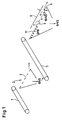
- a sieve (2) is placed for pre-classification.
- the fraction 0/45 is on the sieve (2) designed as a vibrating sieve with the Mesh size 50 mm x 50 mm sieved.
- the plastic and rubber plates as well some dowels (13).
- the dowels (13) and their fragments however, only partially pass into oversize, as during transport on the sieve bottom (2) numerous dowels (13) or their fragments upright and through the sieve openings (3) fall through.
- the sieve (6) points in the task area a smaller mesh size of about 10 mm, which serves to pre-screen the fine grain of fraction 0/45. Below the task, the mesh size is approximately 52 mm x 52 mm.
- a cover plate is located at a distance a from the sieve bottom (7) (8), in its place the chain sling according to the invention is arranged, the free space above the sieve bottom (7) with at least in the area of the screen openings (9) Mesh size limited to 52 mm.
- the distance a is like this chosen that the dowels (13) or their parts in the Free space between the sieve plate (7) and cover plate (8), at the Place the chain sling is arranged according to the invention, do not stand up during transport on the sieve tray (7) and can fall through the sieve openings (9).
- the distance a is, for example, 60 mm, so that the fraction 0/45 unhindered in the space between the sieve plate (7) and Cover plate (8), in its place the chain sling according to the invention is arranged, can go through. An erection of the 160 mm long dowels (13) are excluded. Hence remain the dowels (13) on the sieve plate (7) and are from the mineral mixture 0/45 separated.
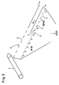
- FIG. 2 in the functionally identical parts with the same item numbers shows a comparable arrangement to separate one from at least two different ones Fractions existing solid mixture.
- Fig. 3 shows a detailed view of the chain suspension (12), the instead of the known cover plates is arranged and limits the free space above the sieve plate (7).
- the Weight of the sling, preferably made from link chains (12) prevents the dowels (13) from erecting however in the event of blockages in the chain hanger (12) and the sieve bottom (7) formed space easily after, so that disturbances of the material flow are largely excluded are.
- the preliminary screening shown in FIGS. 1 and 2 can through the use of the chain suspension also with fractions Oversize is eliminated without reducing operational safety would.
- FIG. 4 finally shows a view of a cover plate (8), which is known per se and is arranged at a distance a from the sieve bottom (7), and in its place the chain suspension is arranged according to the invention.
- the distance a is shown there as borderline.
- the dowel (13) shown in FIG. 4 could reach the mineral mixture 0/45 through the sieve opening (9) in the worst case, given the mesh size m.
- the distance a is reduced slightly, it is impossible for the dowels (13) to pass through the sieve openings (9) into the mineral mixture 0/45 if all other dowels have the minimum dimensions d d and l d shown in FIG. 4.
- Fig. 4 illustrates that for a given dowel size, the maximum distance between the cover plate (8) and the chain sling (12) provided according to the invention also depends, among other things, on the sieve plate thickness d b .
- the distance a and thus the upper grain boundary of the second fraction can be calculated from the given quantities d d , l d , d b , m and ⁇ .
Landscapes
- Combined Means For Separation Of Solids (AREA)
- Pens And Brushes (AREA)
- Piezo-Electric Or Mechanical Vibrators, Or Delay Or Filter Circuits (AREA)
- Polishing Bodies And Polishing Tools (AREA)
Description
- Fig. 1
- Eine Anordnung mit separater Sieb-Vorklassierung,
- Fig. 2
- eine alternative Anordnung mit Vorklassierung durch Zwei-Deck-Sieb,
- Fig. 3
- eine erfindungsgemäße Anordnung ohne Vorklassierung mit einem Gehänge aus mehreren Ketten,
- Fig. 4
- eine Detailansicht einer im Abstand a zum Siebboden angeordneten Abdeckplatte entsprechend Fig. 1, wobei Figuren 1, 2 und 4 keine Ausführungsbeispiele der Erfindung darstellen.
Claims (6)
- Anordnung zum Trennen von einem aus mindestens zwei unterschiedlichen Fraktionen bestehenden Feststoffgemisch nach der Form, wobei die erste Fraktion länglich und die zweite Fraktion annähernd kubisch ist und die Längserstreckung des Feststoffes der ersten Fraktion größer als die längste Längserstreckung der zweiten Fraktion ist, die einen Siebboden (7) mit einer Maschenweite für den Durchgang der zweiten Fraktion und in einem Abstand (a) zum Siebboden (7) angeordnete Mittel aufweist, die den Freiraum oberhalb des Siebbodens (7) zumindest im Bereich der Sieböffnungen (9) begrenzen, wobei der Abstand (a) mindestens der größten Korndicke der zweiten Fraktion entspricht, jedoch in jedem Fall kleiner als die geringste Längserstreckung der ersten Fraktion ist, so daß sich das Feststoffgemisch der ersten Fraktion beim Absieben nicht aufrichten und durch den Siebboden (7) fallen kann, dadurch gekennzeichnet, daß der Freiraum oberhalb des Siebbodens (7) durch ein im Abstand zum Siebboden (7) endendes Gehänge (12) aus mehreren Ketten begrenzt ist.
- Anordnung zum Trennen von Feststoffgemisch nach Anspruch 1, dadurch gekennzeichnet, daß die Ketten als Gliederketten ausgebildet sind.
- Anordnung zum Trennen von Feststoffgemisch nach Anspruch 1 oder 2, dadurch gekennzeichnet, daß dem Siebboden (7) mit Freiraumbegrenzung eine Vorklassierung vorgeschaltet ist.
- Anordnung zum Trennen von Feststoffgemisch nach Anspruch 3, dadurch gekennzeichnet, daß die Vorklassierung ein Sieb (2) mit geringfügig kleinerer Maschenweite als das Sieb (6) mit Freiraumbegrenzung umfaßt und beide Siebe (2,6) vorzugsweise zu einem Zwei-Deck-Sieb zusammengefaßt sind.
- Anordnung zum Trennen von Feststoffgemisch nach Anspruch 3, dadurch gekennzeichnet, daß die Vorklassierung einen Windsichter umfaßt, in dessen Leichtgut die auf dem Sieb (6) mit Freiraumbegrenzung zu trennenden Fraktionen enthalten sind und in dessen Schwergut das Überkorn des Feststoffgemisches enthalten ist.
- Anordnung zum Trennen von Feststoffgemisch nach einem der Ansprüche 3-5, dadurch gekennzeichnet, daß dem Sieb (6) mit Freiraumbegrenzung ein insbesondere in dessen Siebboden integriertes Feinsieb für das Feinkorn der zweiten Fraktion vorgeschaltet ist.
Applications Claiming Priority (2)
| Application Number | Priority Date | Filing Date | Title |
|---|---|---|---|
| DE19526841 | 1995-07-22 | ||
| DE19526841A DE19526841C1 (de) | 1995-07-22 | 1995-07-22 | Anordnung zum Trennen nach der Form |
Publications (2)
| Publication Number | Publication Date |
|---|---|
| EP0755725A1 EP0755725A1 (de) | 1997-01-29 |
| EP0755725B1 true EP0755725B1 (de) | 1998-11-04 |
Family
ID=7767549
Family Applications (1)
| Application Number | Title | Priority Date | Filing Date |
|---|---|---|---|
| EP96104082A Expired - Lifetime EP0755725B1 (de) | 1995-07-22 | 1996-03-15 | Anordnung zum Trennen nach der Form |
Country Status (3)
| Country | Link |
|---|---|
| EP (1) | EP0755725B1 (de) |
| AT (1) | ATE172894T1 (de) |
| DE (2) | DE19526841C1 (de) |
Families Citing this family (2)
| Publication number | Priority date | Publication date | Assignee | Title |
|---|---|---|---|---|
| FR2841161A1 (fr) * | 2002-06-21 | 2003-12-26 | Vibration Ind | Dispositif de tri de produits allonges |
| DE102007052473A1 (de) | 2007-11-02 | 2009-05-07 | Schott Solar Gmbh | Verfahren und Vorrichtung zum Aussieben von Partikeln |
Family Cites Families (2)
| Publication number | Priority date | Publication date | Assignee | Title |
|---|---|---|---|---|
| US2356295A (en) * | 1942-05-07 | 1944-08-22 | Remington Arms Co Inc | Article classifying device |
| US4181603A (en) * | 1978-08-30 | 1980-01-01 | Eli Lilly And Company | Capsule sorting apparatus |
-
1995
- 1995-07-22 DE DE19526841A patent/DE19526841C1/de not_active Expired - Fee Related
-
1996
- 1996-03-15 DE DE59600764T patent/DE59600764D1/de not_active Expired - Fee Related
- 1996-03-15 AT AT96104082T patent/ATE172894T1/de not_active IP Right Cessation
- 1996-03-15 EP EP96104082A patent/EP0755725B1/de not_active Expired - Lifetime
Also Published As
| Publication number | Publication date |
|---|---|
| DE19526841C1 (de) | 1996-10-02 |
| EP0755725A1 (de) | 1997-01-29 |
| DE59600764D1 (de) | 1998-12-10 |
| ATE172894T1 (de) | 1998-11-15 |
Similar Documents
| Publication | Publication Date | Title |
|---|---|---|
| DE69721199T2 (de) | Verfahren und Vorrichtung zum Sortieren von wiederverwertbaren Materialien | |
| DE69714152T2 (de) | Schwingendes Fingersieb mit seitlichen Ablenkkeilen | |
| EP0456666B1 (de) | Anlage zur behandlung von wertstoffen aus baustellenabfällen oder gewerbemüll | |
| DE69418785T2 (de) | Sortiervorrichtung für Nichteisenmaterialien | |
| DE69308025T2 (de) | Vorrichtung und verfahren zum trennen von wiederverwertbarem material | |
| DE69811481T2 (de) | Sortieren von abfallmaterial | |
| DE3505502A1 (de) | Tabak-klassiervorrichtung | |
| DE3932645C2 (de) | Materialklassiervorrichtung | |
| DE1758896B1 (de) | Vorrichtung zum Klassifizieren mit unterschiedlich geneigten Systemen von Hindernissen | |
| EP0755725B1 (de) | Anordnung zum Trennen nach der Form | |
| EP0028792B1 (de) | Mehrdecksiebmaschine | |
| EP0482683A1 (de) | Verfahren und Vorrichtung zum Trennen eines Schüttgutstromes in Fraktionen mit unterschiedlicher Korngrösse | |
| EP0774302B1 (de) | Verfahren und Vorrichtung zur Trennung eines aus Feststoffpartikeln unterschiedlicher Gestalt, Grösse und/oder Dichte bestehenden Gutes in mindestens zwei Komponenten | |
| DE2735510C3 (de) | Verfahren und Vorrichtung zur Sichtung und zur Bildung von Platten, insbesondere im Zuge der Herstellung von Holzplatten | |
| EP0824972B1 (de) | Verfahren zum Trennen eines Feststoffgemisches | |
| DE4413288C2 (de) | Vorrichtung zur Selektion von Bauschutt | |
| DE102020125280B3 (de) | Schwingsiebmaschine | |
| DE19517850C2 (de) | Siebmaschine zur Vorsortierung von Materialmischungen | |
| EP1206978B1 (de) | Vorrichtung zur Sortierung, Unterteilung einer Fraktion | |
| EP0649349A1 (de) | Verfahren und vorrichtung zum sieben eines schüttgutstroms | |
| DE4434748C2 (de) | Verfahren und Vorrichtung zur Trennung eines Schüttgutgemisches | |
| DE19833128C2 (de) | Verfahren und Vorrichtung zum Sortieren von Gesteinsbrocken | |
| DE4438676C1 (de) | Vorrichtung zum Vorsortieren und Transportieren von Altglas | |
| EP3544746B1 (de) | Verwendung einer münzaussortiervorrichtung zum aussortieren von münzen aus einer metallschüttung | |
| DE1758896C (de) | Vorrichtung zum Klassieren mit unterschiedlich geneigten Systemen von Hindernissen |
Legal Events
| Date | Code | Title | Description |
|---|---|---|---|
| PUAI | Public reference made under article 153(3) epc to a published international application that has entered the european phase |
Free format text: ORIGINAL CODE: 0009012 |
|
| AK | Designated contracting states |
Kind code of ref document: A1 Designated state(s): AT BE CH DE DK ES FR IT LI NL |
|
| 17P | Request for examination filed |
Effective date: 19970408 |
|
| 17Q | First examination report despatched |
Effective date: 19971008 |
|
| GRAG | Despatch of communication of intention to grant |
Free format text: ORIGINAL CODE: EPIDOS AGRA |
|
| GRAG | Despatch of communication of intention to grant |
Free format text: ORIGINAL CODE: EPIDOS AGRA |
|
| GRAH | Despatch of communication of intention to grant a patent |
Free format text: ORIGINAL CODE: EPIDOS IGRA |
|
| GRAH | Despatch of communication of intention to grant a patent |
Free format text: ORIGINAL CODE: EPIDOS IGRA |
|
| GRAA | (expected) grant |
Free format text: ORIGINAL CODE: 0009210 |
|
| AK | Designated contracting states |
Kind code of ref document: B1 Designated state(s): AT BE CH DE DK ES FR IT LI NL |
|
| PG25 | Lapsed in a contracting state [announced via postgrant information from national office to epo] |
Ref country code: NL Free format text: LAPSE BECAUSE OF FAILURE TO SUBMIT A TRANSLATION OF THE DESCRIPTION OR TO PAY THE FEE WITHIN THE PRESCRIBED TIME-LIMIT Effective date: 19981104 Ref country code: IT Free format text: LAPSE BECAUSE OF FAILURE TO SUBMIT A TRANSLATION OF THE DESCRIPTION OR TO PAY THE FEE WITHIN THE PRESCRIBED TIME-LIMIT;WARNING: LAPSES OF ITALIAN PATENTS WITH EFFECTIVE DATE BEFORE 2007 MAY HAVE OCCURRED AT ANY TIME BEFORE 2007. THE CORRECT EFFECTIVE DATE MAY BE DIFFERENT FROM THE ONE RECORDED. Effective date: 19981104 Ref country code: FR Free format text: LAPSE BECAUSE OF FAILURE TO SUBMIT A TRANSLATION OF THE DESCRIPTION OR TO PAY THE FEE WITHIN THE PRESCRIBED TIME-LIMIT Effective date: 19981104 Ref country code: ES Free format text: THE PATENT HAS BEEN ANNULLED BY A DECISION OF A NATIONAL AUTHORITY Effective date: 19981104 |
|
| REF | Corresponds to: |
Ref document number: 172894 Country of ref document: AT Date of ref document: 19981115 Kind code of ref document: T |
|
| REG | Reference to a national code |
Ref country code: CH Ref legal event code: EP |
|
| REF | Corresponds to: |
Ref document number: 59600764 Country of ref document: DE Date of ref document: 19981210 |
|
| PG25 | Lapsed in a contracting state [announced via postgrant information from national office to epo] |
Ref country code: DK Free format text: LAPSE BECAUSE OF FAILURE TO SUBMIT A TRANSLATION OF THE DESCRIPTION OR TO PAY THE FEE WITHIN THE PRESCRIBED TIME-LIMIT Effective date: 19990204 |
|
| PG25 | Lapsed in a contracting state [announced via postgrant information from national office to epo] |
Ref country code: AT Free format text: LAPSE BECAUSE OF NON-PAYMENT OF DUE FEES Effective date: 19990315 |
|
| PG25 | Lapsed in a contracting state [announced via postgrant information from national office to epo] |
Ref country code: BE Free format text: LAPSE BECAUSE OF NON-PAYMENT OF DUE FEES Effective date: 19990331 |
|
| NLV1 | Nl: lapsed or annulled due to failure to fulfill the requirements of art. 29p and 29m of the patents act | ||
| EN | Fr: translation not filed | ||
| PLBE | No opposition filed within time limit |
Free format text: ORIGINAL CODE: 0009261 |
|
| STAA | Information on the status of an ep patent application or granted ep patent |
Free format text: STATUS: NO OPPOSITION FILED WITHIN TIME LIMIT |
|
| BERE | Be: lapsed |
Owner name: BSR NATURSTEIN-AUFBEREITUNGS G.M.B.H. Effective date: 19990331 |
|
| 26N | No opposition filed | ||
| REG | Reference to a national code |
Ref country code: CH Ref legal event code: PL |
|
| PGFP | Annual fee paid to national office [announced via postgrant information from national office to epo] |
Ref country code: CH Payment date: 20001127 Year of fee payment: 5 |
|
| REG | Reference to a national code |
Ref country code: CH Ref legal event code: AEN Free format text: DAS PATENT IST AUFGRUND DES WEITERBEHANDLUNGSANTRAGS VOM 24.11.2000 REAKTIVIERT WORDEN. |
|
| PG25 | Lapsed in a contracting state [announced via postgrant information from national office to epo] |
Ref country code: LI Free format text: LAPSE BECAUSE OF NON-PAYMENT OF DUE FEES Effective date: 20010331 Ref country code: CH Free format text: LAPSE BECAUSE OF NON-PAYMENT OF DUE FEES Effective date: 20010331 |
|
| REG | Reference to a national code |
Ref country code: CH Ref legal event code: PL |
|
| PGFP | Annual fee paid to national office [announced via postgrant information from national office to epo] |
Ref country code: DE Payment date: 20020318 Year of fee payment: 7 |
|
| PG25 | Lapsed in a contracting state [announced via postgrant information from national office to epo] |
Ref country code: DE Free format text: LAPSE BECAUSE OF NON-PAYMENT OF DUE FEES Effective date: 20031001 |