EP0751321B1 - Vorrichtung zur Verringerung der Ventilationsverluste eines schnellaufenden Zahnradgetriebes - Google Patents
Vorrichtung zur Verringerung der Ventilationsverluste eines schnellaufenden Zahnradgetriebes Download PDFInfo
- Publication number
- EP0751321B1 EP0751321B1 EP96250141A EP96250141A EP0751321B1 EP 0751321 B1 EP0751321 B1 EP 0751321B1 EP 96250141 A EP96250141 A EP 96250141A EP 96250141 A EP96250141 A EP 96250141A EP 0751321 B1 EP0751321 B1 EP 0751321B1
- Authority
- EP
- European Patent Office
- Prior art keywords
- pinion
- enclosure
- tooth
- region
- gearbox
- Prior art date
- Legal status (The legal status is an assumption and is not a legal conclusion. Google has not performed a legal analysis and makes no representation as to the accuracy of the status listed.)
- Expired - Lifetime
Links
- 238000009423 ventilation Methods 0.000 title claims description 10
- 239000000314 lubricant Substances 0.000 claims description 9
- 230000015572 biosynthetic process Effects 0.000 claims description 3
- 238000005538 encapsulation Methods 0.000 description 12
- 230000005540 biological transmission Effects 0.000 description 5
- 239000002826 coolant Substances 0.000 description 3
- 238000000605 extraction Methods 0.000 description 3
- 238000007789 sealing Methods 0.000 description 2
- 238000005507 spraying Methods 0.000 description 2
- 210000000078 claw Anatomy 0.000 description 1
- 230000001609 comparable effect Effects 0.000 description 1
- 238000005516 engineering process Methods 0.000 description 1
- 238000002347 injection Methods 0.000 description 1
- 239000007924 injection Substances 0.000 description 1
- 238000004519 manufacturing process Methods 0.000 description 1
- 239000000203 mixture Substances 0.000 description 1
- 230000002093 peripheral effect Effects 0.000 description 1
- 239000007921 spray Substances 0.000 description 1
- 230000003319 supportive effect Effects 0.000 description 1
- XLYOFNOQVPJJNP-UHFFFAOYSA-N water Substances O XLYOFNOQVPJJNP-UHFFFAOYSA-N 0.000 description 1
Images


Classifications
-
- F—MECHANICAL ENGINEERING; LIGHTING; HEATING; WEAPONS; BLASTING
- F16—ENGINEERING ELEMENTS AND UNITS; GENERAL MEASURES FOR PRODUCING AND MAINTAINING EFFECTIVE FUNCTIONING OF MACHINES OR INSTALLATIONS; THERMAL INSULATION IN GENERAL
- F16H—GEARING
- F16H57/00—General details of gearing
- F16H57/04—Features relating to lubrication or cooling or heating
- F16H57/048—Type of gearings to be lubricated, cooled or heated
- F16H57/0493—Gearings with spur or bevel gears
-
- F—MECHANICAL ENGINEERING; LIGHTING; HEATING; WEAPONS; BLASTING
- F16—ENGINEERING ELEMENTS AND UNITS; GENERAL MEASURES FOR PRODUCING AND MAINTAINING EFFECTIVE FUNCTIONING OF MACHINES OR INSTALLATIONS; THERMAL INSULATION IN GENERAL
- F16H—GEARING
- F16H57/00—General details of gearing
- F16H57/04—Features relating to lubrication or cooling or heating
- F16H57/0412—Cooling or heating; Control of temperature
- F16H57/0415—Air cooling or ventilation; Heat exchangers; Thermal insulations
-
- F—MECHANICAL ENGINEERING; LIGHTING; HEATING; WEAPONS; BLASTING
- F16—ENGINEERING ELEMENTS AND UNITS; GENERAL MEASURES FOR PRODUCING AND MAINTAINING EFFECTIVE FUNCTIONING OF MACHINES OR INSTALLATIONS; THERMAL INSULATION IN GENERAL
- F16H—GEARING
- F16H57/00—General details of gearing
- F16H57/04—Features relating to lubrication or cooling or heating
- F16H57/0456—Lubrication by injection; Injection nozzles or tubes therefor
-
- F—MECHANICAL ENGINEERING; LIGHTING; HEATING; WEAPONS; BLASTING
- F16—ENGINEERING ELEMENTS AND UNITS; GENERAL MEASURES FOR PRODUCING AND MAINTAINING EFFECTIVE FUNCTIONING OF MACHINES OR INSTALLATIONS; THERMAL INSULATION IN GENERAL
- F16H—GEARING
- F16H57/00—General details of gearing
- F16H57/04—Features relating to lubrication or cooling or heating
- F16H57/0409—Features relating to lubrication or cooling or heating characterised by increasing efficiency, e.g. by reducing splash losses
-
- F—MECHANICAL ENGINEERING; LIGHTING; HEATING; WEAPONS; BLASTING
- F16—ENGINEERING ELEMENTS AND UNITS; GENERAL MEASURES FOR PRODUCING AND MAINTAINING EFFECTIVE FUNCTIONING OF MACHINES OR INSTALLATIONS; THERMAL INSULATION IN GENERAL
- F16H—GEARING
- F16H57/00—General details of gearing
- F16H57/04—Features relating to lubrication or cooling or heating
- F16H57/042—Guidance of lubricant
- F16H57/0421—Guidance of lubricant on or within the casing, e.g. shields or baffles for collecting lubricant, tubes, pipes, grooves, channels or the like
- F16H57/0423—Lubricant guiding means mounted or supported on the casing, e.g. shields or baffles for collecting lubricant, tubes or pipes
-
- Y—GENERAL TAGGING OF NEW TECHNOLOGICAL DEVELOPMENTS; GENERAL TAGGING OF CROSS-SECTIONAL TECHNOLOGIES SPANNING OVER SEVERAL SECTIONS OF THE IPC; TECHNICAL SUBJECTS COVERED BY FORMER USPC CROSS-REFERENCE ART COLLECTIONS [XRACs] AND DIGESTS
- Y10—TECHNICAL SUBJECTS COVERED BY FORMER USPC
- Y10T—TECHNICAL SUBJECTS COVERED BY FORMER US CLASSIFICATION
- Y10T74/00—Machine element or mechanism
- Y10T74/19—Gearing
- Y10T74/19991—Lubrication
Definitions
- the invention relates to a device for reducing ventilation losses high-speed gear transmission according to the preamble of the main claim.
- the idle power loss of a transmission is made up of the Bearing idling losses, hydraulic losses and ventilation losses.
- the the latter losses are only in relation to the other losses Peripheral speeds of 50 m / sec. and more important (magazine drive technology 33 (1994) No. 9, pages 60 - 65).
- To reduce the Ventilation losses have already been proposed (US Pat. No. 3,489,034) to which hermetically sealed gearbox to connect a vacuum pump and aspirate the air-lubricant mixture. With this arrangement, on the one hand the loss of ventilation reduces the noise of the meshing Gears reduced and the operating temperature lowered.
- the disadvantage is that constructive effort of the arrangement, as well as the cost of the purchase and that Operating the vacuum pump.
- a generic device is known from US 5,085,100 B1.
- the Device is a high-speed gear transmission with several in one Gear housing arranged and meshing gears.
- all gears are surrounded by a jacket. whereby for unimpeded supply and removal of air and coolant in the Combing area, the jacket covering has an opening.
- the lubricant is injected outside the combing area through an opening in the jacket, wherein the opening is dimensioned so that the coolant supplied shortly after the Injection point can spray again tangentially. In this way, the Swirl losses due to the coolant are kept low.
- the complete one Sheathing all gears corresponds to a smaller gear box inside of the load-bearing gear housing, with approximately equal pressures through the openings prevail within the casing area as well as in the gear housing.
- US-A-3 827 311 shows a driven large wheel (slow-running), the driving pinion being encapsulated via a bearing housing.
- the object of the invention is a device for reducing the Ventilation losses of a high-speed gearbox indicate that simple and is inexpensive to manufacture and which the pressure conditions in the Tooth meshing and gripping area also exploited.
- the generation of the desired negative pressure is supported if in Tooth gripping area the end of the encapsulation is designed so that there is a continuous Enlargement of the uncovered cross-sectional area between pinion and large wheel results.
- the lubricant spraying tangentially in this area has a comparable effect like a water jet pump, provided that the lubricant supply on the Tooth engagement side is arranged.
- the lubricant supply is also open the tooth extraction side possible, but this would reduce the achievable vacuum worsen.
- the preferred division of the encapsulation in a radial plane has the advantage that you can retrofit this into an already existing gearbox without any problems Can install encapsulation.
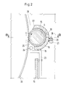
- FIG. 1 is in a cross section and in Figure 2 in a section A-A in Fig. 1 and in Fig. 3 is a view in the direction B-B in Fig. 2 shows a section of a high-speed Gear transmission with the device according to the invention for reducing the Ventilation losses shown.
- the gearbox is arranged in a housing, consisting of a gearbox upper part 1 and a gearbox lower part 2.
- a pinion 4 is fastened on a shaft 3, usually shaft 3 and pinion 4 are made from one piece.
- the shaft 3 is supported on two bearings 5, 6, wherein in this embodiment both are designed as axial bearings.
- two seals 7, 8 are provided, for example here are designed as a labyrinth seal. Depending on requirements and operating conditions other types of seals are used.
- the conclusion of the storage room forms a bearing cover 9 which is attached to the gearbox upper part 1.
- the pinion 4 is encapsulated in such a way that the remaining one Gap 10 is as small as possible.
- the negative pressure that can be created with this encapsulation can only be maintained if the enclosed space is sealed.
- the encapsulation is in divided a radial plane so that it consists of an upper part 15 and a lower part 16th consists.
- the lower part 16 is supported via fastening tabs 17, 18 screwed to a stiffening plate 19 fastened to the lower part 2 of the gearbox are.
- the lower part 16 is also provided with a welded-on claw 20 attached to the gearbox lower part 2 tab 21 connected by screws 30 (Fig. 2).
- FIG. 2 shows in section A-A in FIG. 1 the engagement of the pinion 4 with the large wheel 22.
- the direction of rotation is indicated by arrows.
- the tangential spraying of the lubricant in the tooth extraction region 26 acts supportive in the sense of creating a negative pressure.
- the end region 27 of the encapsulation is designed such that the uncovered Cross-sectional area results in a steady increase if you look at the Tooth extraction region 26 is considered the origin.
- the connection of the upper part 15 the encapsulation with the lower part 16 takes place via screws 28 and dowel pins 29 (FIG 3).
Landscapes
- Engineering & Computer Science (AREA)
- General Engineering & Computer Science (AREA)
- Mechanical Engineering (AREA)
- General Details Of Gearings (AREA)
- Jet Pumps And Other Pumps (AREA)
- Sealing Using Fluids, Sealing Without Contact, And Removal Of Oil (AREA)
Description
- Figur 1
- einen Querschnitt durch einen Teilbereich des Getriebes mit der erfindungsgemäßen Kapselung
- Figur 2
- einen Schnitt A-A in Figur 1
- Figur 3
- eine Ansicht in Richtung B-B in Fig. 2
Claims (4)
- Vorrichtung zur Verringerung der Ventilationsverluste eines schnellaufenden Zahnradgetriebes mit einem Getriebegehäuse und miteinander kämmenden Zahnrädern, die mit einem sie umschließenden Mantel versehen sind und denen im Kämmbereich zur Verminderung der Reibung Schmiermittel zugeführt wird,
dadurch gekennzeichnet,
daß das Zahnradgetriebe in bekannter Weise aus einem Großrad (22) und einem damit kämmenden Ritzel (4) besteht und unter Ausnutzung des im Zahneingriffs- und Ausgriffsbereich sich selbsttätig einstellenden Druckes nur das Ritzel (4) im Bereich von mehr als 180° der Umfangserstreckung eingekapselt ist und im Zahnausgriffsbereich (26) das Ende (27) der Kapselung so gestaltet ist, daß sich eine stetige Vergrößerung der nicht überdeckten Querschnittsfläche zwischen Ritzel (4) und Großrad (22) ergibt und die Kapselung in Bezug auf den verzahnungsfreien Wellenbereich (14) des Ritzels (4) beidseitig abgedichtet ist und sich im verengenden Zahneingriffsbereich (25) von Großrad (22) und Ritzel (4) unmittelbar vor dem Anfang der Kapselung die Zuführleitung (23) für das Schmiermittel mündet. - Vorrichtung nach Anspruch 1,
dadurch gekennzeichnet,
daß auf den verzahnungsfreien Wellenabschnitten (14) des Ritzels (4) je ein Druckkamm angeordnet ist, der gegenüber der Kapselung abgedichtet ist. - Vorrichtung nach Anspruch 1 oder 2,
dadurch gekennzeichnet,
daß die Abdichtung zwischen der stillstehenden Kapselung und dem umlaufenden Ritzel (4) über einen Labyrinthabschnitt (11,12) der Kapselung erfolgt. - Vorrichtung nach Anspruch 1,
dadurch gekennzeichnet, daß die Kapselung in der Radialebene geteilt ist und jedes Teilelement (15,16) über Befestigungsmittel (28,29,30) mit dem Getriebegehäuse (1) verbunden ist.
Applications Claiming Priority (2)
| Application Number | Priority Date | Filing Date | Title |
|---|---|---|---|
| DE19525102A DE19525102C2 (de) | 1995-06-29 | 1995-06-29 | Vorrichtung zur Verringerung der Ventilationsverluste eines schnellaufenden Zahnradgetriebes |
| DE19525102 | 1995-06-29 |
Publications (3)
| Publication Number | Publication Date |
|---|---|
| EP0751321A2 EP0751321A2 (de) | 1997-01-02 |
| EP0751321A3 EP0751321A3 (de) | 1998-01-28 |
| EP0751321B1 true EP0751321B1 (de) | 2001-02-28 |
Family
ID=7766462
Family Applications (1)
| Application Number | Title | Priority Date | Filing Date |
|---|---|---|---|
| EP96250141A Expired - Lifetime EP0751321B1 (de) | 1995-06-29 | 1996-06-28 | Vorrichtung zur Verringerung der Ventilationsverluste eines schnellaufenden Zahnradgetriebes |
Country Status (4)
| Country | Link |
|---|---|
| US (1) | US5749267A (de) |
| EP (1) | EP0751321B1 (de) |
| DE (2) | DE19525102C2 (de) |
| NO (1) | NO312378B1 (de) |
Families Citing this family (5)
| Publication number | Priority date | Publication date | Assignee | Title |
|---|---|---|---|---|
| DE19860353C1 (de) * | 1998-12-28 | 2000-06-21 | Renk Ag | Getriebe |
| DE29908542U1 (de) * | 1999-05-14 | 2000-01-05 | Lindauer Dornier Gmbh, 88131 Lindau | Zahnradabdeckung |
| DE102007041318A1 (de) * | 2007-08-31 | 2009-03-05 | GM Global Technology Operations, Inc., Detroit | Schaltgetriebe mit Zahnradpumpe |
| JP2009156368A (ja) * | 2007-12-27 | 2009-07-16 | Aisin Aw Co Ltd | 歯車回転伝達装置 |
| JP4949284B2 (ja) * | 2008-01-30 | 2012-06-06 | 株式会社リコー | 歯車駆動装置、及びこれを備えた画像形成装置 |
Family Cites Families (9)
| Publication number | Priority date | Publication date | Assignee | Title |
|---|---|---|---|---|
| US1220810A (en) * | 1915-09-01 | 1917-03-27 | Gen Electric | Spur-gearing. |
| US1912422A (en) * | 1931-09-11 | 1933-06-06 | Laval Steam Turbine Co | Lubricating means for gearing |
| US3006439A (en) * | 1958-02-28 | 1961-10-31 | Reserve Mining Co | Housing for spray lubricating system |
| US3489034A (en) * | 1968-05-17 | 1970-01-13 | Gen Electric | Evacuated gear casing |
| FR2153694A5 (de) * | 1971-09-21 | 1973-05-04 | Creusot Loire | |
| GB2153018A (en) * | 1984-01-17 | 1985-08-14 | Smidth & Co As F L | Rotary drum with grease lubricating apparatus |
| JPS6321806Y2 (de) * | 1985-04-01 | 1988-06-15 | ||
| US5085100A (en) * | 1989-10-18 | 1992-02-04 | Bell Helicopter Textron Inc. | Gear shrouding system |
| DE4321655A1 (de) * | 1993-06-30 | 1995-01-12 | Rudolf Stegherr | Einrichtung zur Schmierung von schnellaufenden Zahnradgetrieben durch einen Öltransport, bewirkt durch die rotierenden Zahnräder selbst |
-
1995
- 1995-06-29 DE DE19525102A patent/DE19525102C2/de not_active Expired - Lifetime
-
1996
- 1996-06-26 US US08/670,902 patent/US5749267A/en not_active Expired - Fee Related
- 1996-06-27 NO NO19962735A patent/NO312378B1/no unknown
- 1996-06-28 EP EP96250141A patent/EP0751321B1/de not_active Expired - Lifetime
- 1996-06-28 DE DE59606481T patent/DE59606481D1/de not_active Expired - Lifetime
Also Published As
| Publication number | Publication date |
|---|---|
| DE19525102C2 (de) | 1999-06-10 |
| NO962735D0 (no) | 1996-06-27 |
| US5749267A (en) | 1998-05-12 |
| NO962735L (no) | 1996-12-30 |
| DE19525102A1 (de) | 1997-01-02 |
| DE59606481D1 (de) | 2001-04-05 |
| EP0751321A2 (de) | 1997-01-02 |
| EP0751321A3 (de) | 1998-01-28 |
| NO312378B1 (no) | 2002-04-29 |
Similar Documents
| Publication | Publication Date | Title |
|---|---|---|
| DE2200497C3 (de) | Zweistufiges Frontgebläse für ein Gasturbinenstrahltriebwerk | |
| EP0592803B1 (de) | Getriebe-Mehrwellenturbokompressor | |
| EP3368797B1 (de) | Stirnradgetriebe | |
| DE3943103A1 (de) | Turbogeblaesetriebwerk mit einem hohen bypass-verhaeltnis | |
| DE4108658C2 (de) | Kraftfahrzeug mit einem einem Zahnräderwechselgetriebe nachgeschalteten, hydrodynamischen Retarder | |
| DE3235378A1 (de) | Antriebsvorrichtung | |
| EP3221590B1 (de) | Getriebe und getriebeturbomaschine | |
| DE1291164B (de) | Zweiwellengasturbinentriebwerk | |
| DE2836094C2 (de) | Anordnung einer Ölpumpe | |
| DE4220754C2 (de) | Getriebe für Antriebe von Schienentriebfahrzeugen | |
| EP0290664B1 (de) | Zweiwellenpumpe | |
| DE69100968T2 (de) | Turbomaschinenstufe mit vermindertem Strömungsverlust. | |
| DE19525102C2 (de) | Vorrichtung zur Verringerung der Ventilationsverluste eines schnellaufenden Zahnradgetriebes | |
| DE60107599T2 (de) | Einfassung für ölgeschmierte drehglieder | |
| WO2023011894A1 (de) | Stirnradgetriebe | |
| DE3716083A1 (de) | Innenachsige drehkolbenmaschine | |
| DE3605246C2 (de) | Zahnradmaschine (Pumpe oder Motor) | |
| DE2627543A1 (de) | Kolbendichtungen fuer drehvorrichtungen | |
| DE4244685C2 (de) | Getriebe für Antriebe von Schienentriebfahrzeugen | |
| DE2324880A1 (de) | Gehaeuse eines gaserzeugers fuer gasturbinen | |
| DE924000C (de) | Verbrennungsmotor | |
| DE1953146A1 (de) | Antrieb einer Arbeitsmaschine ueber Getriebe | |
| DE69716626T2 (de) | Antriebsvorrichtung für eine servopumpe und getriebegehäuse in einem fahrzeug | |
| EP0584427B1 (de) | Zweitakt-Hubkolbenbrennkraftmaschine | |
| DE4321655A1 (de) | Einrichtung zur Schmierung von schnellaufenden Zahnradgetrieben durch einen Öltransport, bewirkt durch die rotierenden Zahnräder selbst |
Legal Events
| Date | Code | Title | Description |
|---|---|---|---|
| PUAI | Public reference made under article 153(3) epc to a published international application that has entered the european phase |
Free format text: ORIGINAL CODE: 0009012 |
|
| AK | Designated contracting states |
Kind code of ref document: A2 Designated state(s): CH DE FR GB IT LI NL |
|
| PUAL | Search report despatched |
Free format text: ORIGINAL CODE: 0009013 |
|
| AK | Designated contracting states |
Kind code of ref document: A3 Designated state(s): CH DE FR GB IT LI NL |
|
| 17P | Request for examination filed |
Effective date: 19980619 |
|
| 17Q | First examination report despatched |
Effective date: 19990914 |
|
| GRAG | Despatch of communication of intention to grant |
Free format text: ORIGINAL CODE: EPIDOS AGRA |
|
| GRAG | Despatch of communication of intention to grant |
Free format text: ORIGINAL CODE: EPIDOS AGRA |
|
| GRAH | Despatch of communication of intention to grant a patent |
Free format text: ORIGINAL CODE: EPIDOS IGRA |
|
| GRAH | Despatch of communication of intention to grant a patent |
Free format text: ORIGINAL CODE: EPIDOS IGRA |
|
| RAP1 | Party data changed (applicant data changed or rights of an application transferred) |
Owner name: ATECS MANNESMANN AG |
|
| GRAA | (expected) grant |
Free format text: ORIGINAL CODE: 0009210 |
|
| AK | Designated contracting states |
Kind code of ref document: B1 Designated state(s): CH DE FR GB IT LI NL |
|
| REG | Reference to a national code |
Ref country code: CH Ref legal event code: NV Representative=s name: E. BLUM & CO. PATENTANWAELTE Ref country code: CH Ref legal event code: EP |
|
| ET | Fr: translation filed | ||
| GBT | Gb: translation of ep patent filed (gb section 77(6)(a)/1977) |
Effective date: 20010302 |
|
| REF | Corresponds to: |
Ref document number: 59606481 Country of ref document: DE Date of ref document: 20010405 |
|
| ITF | It: translation for a ep patent filed | ||
| REG | Reference to a national code |
Ref country code: GB Ref legal event code: IF02 |
|
| PLBE | No opposition filed within time limit |
Free format text: ORIGINAL CODE: 0009261 |
|
| STAA | Information on the status of an ep patent application or granted ep patent |
Free format text: STATUS: NO OPPOSITION FILED WITHIN TIME LIMIT |
|
| 26N | No opposition filed | ||
| REG | Reference to a national code |
Ref country code: CH Ref legal event code: PFA Owner name: ATECS MANNESMANN AG Free format text: ATECS MANNESMANN AG#MANNESMANNUFER 2#40213 DUESSELDORF (DE) -TRANSFER TO- ATECS MANNESMANN AG#MANNESMANNUFER 2#40213 DUESSELDORF (DE) |
|
| PGFP | Annual fee paid to national office [announced via postgrant information from national office to epo] |
Ref country code: NL Payment date: 20110617 Year of fee payment: 16 |
|
| PGFP | Annual fee paid to national office [announced via postgrant information from national office to epo] |
Ref country code: IT Payment date: 20120626 Year of fee payment: 17 |
|
| REG | Reference to a national code |
Ref country code: NL Ref legal event code: V1 Effective date: 20130101 |
|
| PG25 | Lapsed in a contracting state [announced via postgrant information from national office to epo] |
Ref country code: NL Free format text: LAPSE BECAUSE OF NON-PAYMENT OF DUE FEES Effective date: 20130101 |
|
| PG25 | Lapsed in a contracting state [announced via postgrant information from national office to epo] |
Ref country code: IT Free format text: LAPSE BECAUSE OF NON-PAYMENT OF DUE FEES Effective date: 20130628 |
|
| REG | Reference to a national code |
Ref country code: FR Ref legal event code: PLFP Year of fee payment: 20 |
|
| PGFP | Annual fee paid to national office [announced via postgrant information from national office to epo] |
Ref country code: GB Payment date: 20150608 Year of fee payment: 20 |
|
| PGFP | Annual fee paid to national office [announced via postgrant information from national office to epo] |
Ref country code: FR Payment date: 20150610 Year of fee payment: 20 |
|
| PGFP | Annual fee paid to national office [announced via postgrant information from national office to epo] |
Ref country code: DE Payment date: 20150821 Year of fee payment: 20 Ref country code: CH Payment date: 20150902 Year of fee payment: 20 |
|
| REG | Reference to a national code |
Ref country code: DE Ref legal event code: R071 Ref document number: 59606481 Country of ref document: DE |
|
| REG | Reference to a national code |
Ref country code: CH Ref legal event code: PL |
|
| REG | Reference to a national code |
Ref country code: GB Ref legal event code: PE20 Expiry date: 20160627 |
|
| PG25 | Lapsed in a contracting state [announced via postgrant information from national office to epo] |
Ref country code: GB Free format text: LAPSE BECAUSE OF EXPIRATION OF PROTECTION Effective date: 20160627 |