EP0751088A1 - Einrichtung zur Erzeugung von Schachtinformation - Google Patents
Einrichtung zur Erzeugung von Schachtinformation Download PDFInfo
- Publication number
- EP0751088A1 EP0751088A1 EP96109400A EP96109400A EP0751088A1 EP 0751088 A1 EP0751088 A1 EP 0751088A1 EP 96109400 A EP96109400 A EP 96109400A EP 96109400 A EP96109400 A EP 96109400A EP 0751088 A1 EP0751088 A1 EP 0751088A1
- Authority
- EP
- European Patent Office
- Prior art keywords
- receiver
- door
- cover plate
- transmitter
- floor
- Prior art date
- Legal status (The legal status is an assumption and is not a legal conclusion. Google has not performed a legal analysis and makes no representation as to the accuracy of the status listed.)
- Granted
Links
- 230000005693 optoelectronics Effects 0.000 claims abstract 2
- 102100037354 Ectodysplasin-A Human genes 0.000 claims description 9
- 101000880080 Homo sapiens Ectodysplasin-A Proteins 0.000 claims description 9
- 230000005540 biological transmission Effects 0.000 claims description 6
- 230000006870 function Effects 0.000 claims description 5
- 101150111792 sda1 gene Proteins 0.000 description 3
- 230000004888 barrier function Effects 0.000 description 2
- 101000599778 Homo sapiens Insulin-like growth factor 2 mRNA-binding protein 1 Proteins 0.000 description 1
- 101000988591 Homo sapiens Minor histocompatibility antigen H13 Proteins 0.000 description 1
- 101000960626 Homo sapiens Mitochondrial inner membrane protease subunit 2 Proteins 0.000 description 1
- 101000828788 Homo sapiens Signal peptide peptidase-like 3 Proteins 0.000 description 1
- 102100029083 Minor histocompatibility antigen H13 Human genes 0.000 description 1
- 102100023501 Signal peptide peptidase-like 3 Human genes 0.000 description 1
- 230000002411 adverse Effects 0.000 description 1
- 238000010586 diagram Methods 0.000 description 1
- 238000009434 installation Methods 0.000 description 1
Images


Classifications
-
- B—PERFORMING OPERATIONS; TRANSPORTING
- B66—HOISTING; LIFTING; HAULING
- B66B—ELEVATORS; ESCALATORS OR MOVING WALKWAYS
- B66B1/00—Control systems of elevators in general
- B66B1/34—Details, e.g. call counting devices, data transmission from car to control system, devices giving information to the control system
- B66B1/46—Adaptations of switches or switchgear
- B66B1/50—Adaptations of switches or switchgear with operating or control mechanisms mounted in the car or cage or in the lift well or hoistway
Definitions
- the invention relates to a device for generating shaft information consisting of information transmitters arranged in the door area of an elevator car and actuating elements arranged in the door area of a floor door, which actuate the information transmitters in an elevator shaft depending on the position of the elevator car.
- a shaft information transmitter which consists of switches arranged one above the other on the door side of the cabin and of contact tabs or switching magnets arranged on the door jamb of the storey door.
- the switches arranged on the cabin are actuated one after the other by means of the contact flag or switching magnets of the floor.
- the switch signals are used by the elevator control for switching functions such as speed changeover, fine adjustment, brake application, step-by-step switching, etc.
- a disadvantage of the known device is that switches in the cabin door area and contact tab or switching magnets in the landing door area take up a lot of space and are structurally difficult to accommodate. In addition, the hysteresis of the switches adversely affects the accuracy of the switch signals.
- the invention seeks to remedy this.
- the invention as characterized in the claims, solves the problem of avoiding the disadvantages of the known device and of providing a shaft information transmitter arranged on an elevator car, even with tightly dimensioned shaft cross-sections or entrance areas, with its signals the elevator car can be positioned very precisely on the floor.
- the advantages achieved by the invention are essentially to be seen in the fact that existing safety systems in the cabin door area can be used to generate shaft information, that the shaft information transmitter generates path signals for controlling the elevator drive, and that data can be transmitted between the cabin and the floor door using the shaft information transmitter.
- 1 denotes an elevator car, which stands on a floor 2.
- the elevator car 1 is moved in an elevator shaft 4 formed by shaft walls 3.
- the elevator car 1 is on the floor 2.
- the position of the elevator car 1 is adjusted until a car threshold 5 is flush with a floor threshold 6.
- a cabin door 7 is moved along the cabin threshold 5 and a floor door 8 is moved along the floor threshold 6.
- the car door 7 is opened and closed by a door drive (not shown), the storey door 8 being opened and closed by drivers (not shown) arranged on the car door 7.
- a light receiver is located opposite each light transmitter, so that the light beam from one light transmitter strikes the one light receiver, in which, for example, a photodiode converts the light beam into an electrical signal. If at least one light beam is interrupted by people or objects, the elevator car 1 remains blocked.
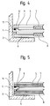
- a cover plate 12 projects into the light curtain 9 and is dimensioned such that a light beam strikes the cover plate 12 instead of the receiver bar 11.
- the cover plate 12 is arranged on a pivotable bolt 13.
- the cover plate 12 projects into the light curtain 9 and covers a light beam.
- the one-story door 8 meets a flag 14 arranged on the bolt 13 and swivels the cover plate 12 out of the light curtain 9.
- the bolt 13 rotates into the starting position under the force of a spring 15 back so that the cover plate 12 protrudes again into the light curtain 9 of the elevator car 1 standing on the floor 2.
- pivotable cover plate 12 lies in the unimpaired function of the light barrier as a safety element when the car door 7 is open and as a position element when the door is closed. Instead of the spring 15, a drive can also take over the pivoting movement of the bolt 13.
- a fixed cover plate 12 is provided.
- a light beam is interrupted when the doors 7, 8 are open. The control must then be able to distinguish whether it is an object or the cover plate 12 itself that interrupts the light beam.
- FIG. 6 shows an elevator installation with several floors 2.1, 2.2, 2.3, several cover plates 12.1, 12.2, 12.3, several floor sleepers 6.1, 6.2, 6.3, a motor 16 which drives a traction sheave 17 by means of which the elevator car 1 and a counterweight 18 is moved in the elevator shaft 4.
- An elevator controller 19 is connected and exchanges data and control commands with a cabin controller 20 and a motor controller 21.
- the light beams from the light curtain 9 strike the light receivers, for example photodiodes D1 ... D16 of the receiver strip 11.
- the incident light beams are converted by the photodiodes D1 ... D16 into electrical signals, which are evaluated by the cabin controller 20. If one or more photodiodes D1 ... D16 do not emit a corresponding signal, the car controller 20 forwards a signal to the elevator controller 19, which blocks the elevator car 1 until all driving conditions, including intact light curtain 9, are met.
- the elevator car 1 In order to determine the exact position of the elevator car 1 in the elevator shaft 4, also called the car position, the elevator car 1 carries out a learning trip in which each floor 12.1, 12.2, 12.3 is approached. In the example shown in FIG. 6, the approached position on the floor 2.2 of the elevator car 1 is such that the cover plate 12.2 covers, for example, the second photodiode D2. This rough position is stored by the elevator control 19. The exact position is approached manually in a second trip and stored as setpoint SD8, for example the position of the eighth diode D8. The elevator car 1 now receives its travel command, for example the second floor 2.2.
- the elevator car 1 moves to the rough position of the photodiode D2 determined in the learning run and lands, for example at the position of the photodiode D3, which is detected by the car control unit 20 due to the light beam interrupted by the cover plate 12.2 and is forwarded as an actual value to the elevator control unit 19.
- a correction value is generated from the setpoint and actual value, with which the elevator car 1 is moved until the elevator car 1 has reached the setpoint position SD8 of the manual learning run.
- the positioning device shown in FIGS. 1 to 6 has been supplemented with a special cover plate and a second transmitter strip.
- the cover plate 12 On the transmitter strip side, the cover plate 12 has been supplemented with a light receiver, for example a first receiver diode EDA1. It takes over the function of the respective diode D1 ... D16 of the receiver strip 11 covered by the cover plate 12.
- the cover plate 12 On the receiver strip side, the cover plate 12 has been supplemented with a light transmitter, for example a transmitter diode SDA1 and a second receiver diode EDA2.
- a second transmitter strip 22 has been arranged on the cabin sill 5 next to the receiver strip 11.
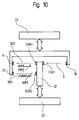
- the data transmission shown in FIG. 10 now exists between the covered diode of the receiver strip 11 and the transmitter diode SDA1 of the cover plate 12 and between the second transmitter strip 22 and the second receiver diode EDA2. Data is only transferred between the diodes, which are covered by the cover plate 12.
- Each diode EDA1, EDA2, SDA1 of the cover plate 12 faces a diode on the transmitter strips 10, 22 or the receiver strip 11.
- the data transmission always takes place in one direction DR1, DR2, it being possible to send and receive data simultaneously.
- the data are converted by a floor computer 23 or by a cabin computer 24 into pulses IMP1, IMP2 and transmitted optoelectronically by means of the diodes.
Landscapes
- Engineering & Computer Science (AREA)
- Automation & Control Theory (AREA)
- Computer Networks & Wireless Communication (AREA)
- Elevator Control (AREA)
- Indicating And Signalling Devices For Elevators (AREA)
- Elevator Door Apparatuses (AREA)
- Window Of Vehicle (AREA)
- Power-Operated Mechanisms For Wings (AREA)
- Liquid Crystal Substances (AREA)
- Golf Clubs (AREA)
Abstract
Description
- Die Erfindung betrifft eine Einrichtung zur Erzeugung von Schachtinformation bestehend aus im Türbereich einer Aufzugskabine angeordneten Informationsgebern und aus im Türbereich einer Stockwerktür angeordneten Betätigungselementen, die die Informationsgeber je nach Lage der Aufzugskabine in einem Aufzugsschacht betätigen.
- Aus der Offenlegungsschrift DE 2 262 396 ist ein Schachtinformationsgeber bekannt geworden, der aus an der Türseite der Kabine übereinander angeordnete Schalter und aus am Türpfosten der Stockwerktür angeordneter Kontaktfahne bzw. Umschaltmagnete besteht. Beim Einfahren der Kabine auf das Stockwerk werden die an der Kabine angeordneten Schalter mittels der Kontaktfahne bzw. Umschaltmagnete des Stockwerkes nacheinander betätigt. Die Schaltersignale werden von der Aufzugsteuerung für Schaltfunktionen wie Geschwindigkeitsumschaltung, Feinabstellung, Bremseinsatz, Weiterschaltung des Schrittschaltwerkes etc. verwendet.
- Ein Nachteil der bekannten Einrichtung liegt darin, dass Schalter im Kabinentürbereich und Kontaktfahne bzw. Umschaltmagnete im Stockwerktürbereich viel Platz beanspruchen und konstruktiv schwer unterzubringen sind. Zudem wirkt sich die Hysterese der Schalter nachteilig auf die Genauigkeit der Schaltersignale aus.
- Hier will die Erfindung Abhilfe schaffen. Die Erfindung, wie sie in den Ansprüchen gekennzeichnet ist, löst die Aufgabe, die Nachteile der bekannten Einrichtung zu vermeiden und einen auch bei knapp bemessenen Schachtquerschnitten bzw. Eingangsbereichen leicht unterzubringenden an einer Aufzugskabine angeordneten Schachtinformationsgeber zu schaffen, mit dessen Signalen die Aufzugskabine auf dem Stockwerk sehr präzise positioniert werden kann.
- Die durch die Erfindung erreichten Vorteile sind im wesentlichen darin zu sehen, dass bestehende Sicherheitssysteme des Kabinentürbereiches zur Erzeugung von Schachtinformation genutzt werden können, dass der Schachtinformationsgeber Wegsignale für die Steuerung des Aufzugsantriebes erzeugt und dass mit dem Schachtinformationsgeber Daten zwischen Kabine und Stockwerktüre übertragen werden können.
- Im folgenden wird die Erfindung anhand von lediglich einen Ausführungsweg darstellenden Zeichnungen näher erläutert. Es zeigen:
- Fig. 1
- einen Grundriss eines Ein-/Ausganges eines Aufzuges mit einem Lichtvorhang,
- Fig. 2
- einen Grundriss einer an einer Stockwerktürschwelle schwenkbar angeordneten Abdeckplatte,
- Fig. 3
- einen Seitenriss der Abdeckplatte gemäss Fig. 2,
- Fig. 4
- die Abdeckplatte in Ruheposition bei geschlossener Stockwerktür,
- Fig. 5
- die durch die offene Stockwerktür betätigte Abdeckplatte,
- Fig. 6
- eine schematische Darstellung eines Schachtinformationsgebers zur Positionierung einer Aufzugskabine,
- Fig. 7
- einen Grundriss der schwenkbar an der Stockwerktürschwelle angeordneten Abdeckplatte mit Sender und Empfängerdioden,
- Fig. 8
- einen Seitenriss der Abdeckplatte gemäss Fig. 7,
- Fig. 9
- eine Einrichtung zur Datenübertragung zwischen der Aufzugskabine und dem Stockwerk und
- Fig. 10
- ein Blockschaltbild zur Datenübertragung zwischen einem Kabinenrechner und einem Stockwerkrechner.
- In den Fig. 1 bis 10 ist mit 1 eine Aufzugskabine bezeichnet, die auf einem Stockwerk 2 steht. Die Aufzugskabine 1 wird in einem durch Schachtwände 3 gebildeten Aufzugsschacht 4 verfahren. In den Figuren steht die Aufzugskabine 1 auf dem Stockwerk 2. Beim Stockwerkhalt wird die Position der Aufzugskabine 1 soweit ausgeregelt, bis eine Kabinenschwelle 5 bündig mit einer Stockwerkschwelle 6 steht. Entlang der Kabinenschwelle 5 wird eine Kabinentür 7 und entlang der Stockwerkschwelle 6 eine Stockwerktür 8 verfahren. Die Kabinentür 7 wird von einem nicht dargestellten Türantrieb geöffnet und geschlossen, dabei wird die Stockwerktür 8 von an der Kabinentür 7 angeordneten nicht dargestellten Mitnehmern geöffnet und geschlossen.
- Ein sich über die Länge der Kabinenschwelle 5 und Kabinentürhöhe erstreckender Lichtvorhang 9 einer Lichtschranke bestehend aus erster Senderleiste 10 und Empfängerleiste 11 blockiert die Aufzugskabine 1 falls Personen oder Gegenstände im Bereich der Kabinentüren 7 oder Stockwerktüren 8 sind. Die sich über die Kabinentürhöhe erstreckende am einen Ende der Kabinenschwelle 5 angeordnete erste Senderleiste 10 mit beispielsweise im Infrarotbereich arbeitenden Lichtquellen erzeugt beispielsweise 16 horizontale Lichtstrahlen, die von der am anderen Ende der Kabinenschwelle 7 angeordneten Empfängerleiste 11 mit Lichtempfängern detektiert werden.
- Je ein Lichtempfänger liegt je einem Lichtsender gegenüber, sodass der Lichtstrahl des einen Lichtsenders auf den einen Lichtempfänger auftrifft, in dem beispielsweise eine Photodiode den Lichtstrahl in ein elektrisches Signal umwandelt. Falls mindestens ein Lichtstrahl von Personen oder Gegenständen unterbrochen wird, bleibt die Aufzugskabine 1 blockiert.
- Am empfängerleistenseitigen Ende der Stockwerkschwelle 6 ragt eine Abdeckplatte 12 in den Lichtvorhang 9 und ist so bemessen, dass ein Lichtstrahl anstatt auf die Empfängerleiste 11 auf die Abdeckplatte 12 trifft. Im vorliegenden Ausführungsbeispiel ist die Abdeckplatte 12 an einem schwenkbaren Bolzen 13 angeordnet. Bei geschlossenen Kabinentüren 7 und Stockwerktüren 8 ragt die Abdeckplatte 12 in den Lichtvorhang 9 und deckt einen Lichtstrahl ab. Beim Öffnungsvorgang der Türen 7, 8 trifft die eine Stockwerktür 8 auf eine am Bolzen 13 angeordnete Fahne 14 und schwenkt die Abdeckplatte 12 aus dem Lichtvorhang 9. Beim Schliessvorgang der Türen 7, 8 dreht der Bolzen 13 unter der Krafteinwirkung einer Feder 15 in die Ausgangslage zurück, sodass die Abdeckplatte 12 wieder in den Lichtvorhang 9 der auf dem Stockwerk 2 stehenden Aufzugskabine 1 ragt.
- Der Vorteil einer schwenkbaren Abdeckplatte 12 liegt in der unbeeinträchtigten Funktion der Lichtschranke als Sicherheitselement bei offener Kabinentür 7 und als Positionselement bei geschlossener Tür. Anstelle der Feder 15 kann auch ein Antrieb die Schwenkbewegung des Bolzens 13 übernehmen.
- In einer weiteren Ausführungsvariante ist eine feste Abdeckplatte 12 vorgesehen. In diesem Fall ist ein Lichtstrahl bei offenen Türen 7, 8 unterbrochen. Die Steuerung muss dann unterscheiden können, ob es sich um einen Gegenstand oder um die Abdeckplatte 12 selbst handelt, der oder die den Lichtstrahl unterbricht.
- Fig. 6 zeigt eine Aufzugsanlage mit mehreren Stockwerken 2.1, 2.2, 2.3, mehreren Abdeckplatten 12.1, 12.2, 12.3, mehreren Stockwerkschwellen 6.1, 6.2, 6.3, einem Motor 16, der eine Treibscheibe 17 antreibt, mittels der die Aufzugskabine 1 und ein Gegengewicht 18 im Aufzugsschacht 4 verfahren wird. Eine Aufzugssteuerung 19 steht in Verbindung und tauscht Daten und Steuerbefehle aus mit einer Kabinensteuerung 20 und einer Motorsteuerung 21. Die Lichtstrahlen des Lichtvorhanges 9 treffen auf die Lichtempfänger, beispielsweise Photodioden D1 ... D16 der Empfängerleiste 11 auf. Die auftreffenden Lichtstrahlen werden von den Photodioden D1 ... D16 in elektrische Signale umgewandelt, die von der Kabinensteuerung 20 ausgewertet werden. Falls eine oder mehrere Photodioden D1 ... D16 kein entsprechendes Signal abgeben, leitet die Kabinensteuerung 20 ein Signal an die Aufzugssteuerung 19 weiter, die die Aufzugskabine 1 solange blockiert, bis sämtliche Fahrbedingungen einschliesslich intakter Lichtvorhang 9 erfüllt sind.
- Zur Bestimmung der genauen Lage der Aufzugskabine 1 im Aufzugsschacht 4, auch Kabinenposition genannt, führt die Aufzugskabine 1 eine Lernfahrt durch, bei der jedes Stockwerk 12.1, 12.2, 12.3 angefahren wird. Im gezeigten Beispiel der Fig. 6 ist die angefahrene Position auf dem Stockwerk 2.2 der Aufzugskabine 1 derart, dass die Abdeckplatte 12.2 beispielsweise die zweite Photodiode D2 abdeckt. Diese Grobposition wird von der Aufzugssteuerung 19 gespeichert. Die genaue Position wird in einer zweiten Fahrt manuell angefahren und als Sollwert SD8, beispielsweise die Position der achten Diode D8 abgespeichert. Die Aufzugskabine 1 erhält nun ihren Fahrbefehl, beispielsweise zweites Stockwerk 2.2. Dabei fährt die Aufzugskabine 1 die in der Lernfahrt ermittelte Grobposition der Photodiode D2 an und landet beispielsweise auf der Position der Photodiode D3, was aufgrund des durch die Abdeckplatte 12.2 unterbrochenen Lichtstrahles von der Kabinensteuerung 20 detektiert wird und als Istwert an die Aufzugssteuerung 19 weitergeleitet wird. Aus Sollwert und Istwert entsteht eine Korrekturgrösse, mit der die Aufzugskabine 1 solange bewegt wird, bis die Aufzugskabine 1 die Sollposition SD8 der manuellen Lernfahrt erreicht hat.
- In den Fig. 7 bis 10 ist die in den Fig. 1 bis 6 gezeigte Positioniereinrichtung mit einer besonderen Abdeckplatte und einer zweiten Senderleiste ergänzt worden. Damit können Daten im Türbereich übertragen werden und die Funktion des Lichtvorhanges 9 als Sicherheitselement in jedem Fall gewährleistet werden. Senderleistenseitig ist die Abdeckplatte 12 mit einem Lichtempfänger, beispielsweise einer ersten Empfängerdiode EDA1 ergänzt worden. Sie übernimmt die Funktion der jeweils durch die Abdeckplatte 12 abgedeckten Diode D1 ... D16 der Empfängerleiste 11. Empfängerleistenseitig ist die Abdeckplatte 12 mit einem Lichtsender, beispielsweise einer Senderdiode SDA1 und einer zweiten Empfängerdiode EDA2 ergänzt worden. An der Kabinenschwelle 5 ist neben der Empfängerleiste 11 eine zweite Senderleiste 22 angeordnet worden. Zwischen der abgedeckten Diode der Empfängerleiste 11 und der Senderdiode SDA1 der Abdeckplatte 12 sowie zwischen der zweiten Senderleiste 22 und der zweiten Empfängerdiode EDA2 besteht nun die Möglichkeit der in Fig. 10 dargestellten Datenübertragung. Die Datenübertragung erfolgt nur zwischen den Dioden, die von der Abdeckplatte 12 abgedeckt werden. Jeder Diode EDA1, EDA2, SDA1 der Abdeckplatte 12 steht eine Diode auf den Senderleisten 10, 22 bzw. der Empfängerleiste 11 gegenüber. Die Datenübertragung erfolgt stets in einer Richtung DR1, DR2, wobei die Möglichkeit besteht, Daten gleichzeitig zu senden und zu empfangen. Die Daten werden von einem Stockwerkrechner 23 bzw. von einem Kabinenrechner 24 in Impulse IMP1, IMP2 umgewandelt und mittels der Dioden optoelektronisch übertragen.
Claims (6)
- Einrichtung zur Erzeugung von Schachtinformation bestehend aus im Türbereich einer Aufzugskabine (1) angeordneten Informationsgebern (10,11) und aus im Türbereich einer Stockwerktür (8) angeordneten Betätigungselementen (12), die die Informationsgeber (10,11) je nach Lage der Aufzugskabine (1) in einem Aufzugsschacht (4) betätigen,
dadurch gekennzeichnet,
dass optoelektronische Informationsgeber (10,11) vorgesehen sind. - Einrichtung nach Anspruch 1,
dadurch gekennzeichnet,
dass eine erste sich im wesentlichen über die Kabinentürhöhe erstreckende einen Lichtvorhang (9) erzeugende Senderleiste (10) mit übereinander angeordneten Lichtsendern und eine sich im wesentlichen über die Kabinentürhöhe erstreckende Empfängerleiste (11) mit übereinander angeordneten Lichtempfängern (D1 ... D16) vorgesehen sind, die die Lichtstrahlen der Lichtsender in elektrische Signale umwandeln, wobei einzelne Lichtstrahlen von einer im Türbereich der Stockwerktür (8) angeordneten in den Lichtvorhang (9) ragenden Abdeckplatte (12) unterbrochen werden. - Einrichtung nach Anspruch 2,
dadurch gekennzeichnet,
dass die erste Senderleiste (10) und die Empfängerleiste (11) an einer Kabinenschwelle (5) und die Abdeckplatte (12) an einer Stockwerkschwelle (6) angeordnet sind. - Einrichtung nach Anspruch 3,
dadurch gekennzeichnet,
dass die Abdeckplatte (12) schwenkbar an einem an der Stockwerkschwelle (6) angeordneten Bolzen (13) mit einer mittels der Stockwerktür (8) betätigbaren Fahne (14) angeordnet ist. - Einrichtung nach einem der vorhergehenden Ansprüche,
dadurch gekennzeichnet,
dass mit einer Lernfahrt der Aufzugskabine (1) je Stockwerk (2.1, 2.2, 2.3) eine Grobposition und mit einer manuellen Lernfahrt die genaue Sollposition aufgrund der unterbrochenen Lichtstrahlen bestimmt wird und
dass aus dem Istwert eines Fahrbefehls und dem Sollwert der manuellen Lernfahrt eine Korrekturgrösse bestimmt wird, mit der die Aufzugskabine (1) solange bewegt wird, bis sie die Sollposition erreicht hat. - Einrichtung nach den Ansprüchen 1 bis 4,
dadurch gekennzeichnet,
dass neben der Empfängerleiste (11) eine zweite Senderleiste (22) angeordnet ist und
dass an der Abdeckplatte (12) eine erste Empfängerdiode (EDA1), eine zweite Empfängerdiode (EDA2) und eine Senderdiode (SDA1) angeordnet sind, wobei die erste Empfängerdiode (EDA1) die Funktion der jeweils durch die Abdeckplatte (12) abgedeckten Diode (D1 ... D16) der Empfängerleiste (11) übernimmt und die zweite Senderleiste (22) zusammen mit der zweiten Empfängerdiode (EDA2) die Datenübertragung in der einen Richtung (DR1) und die Senderdiode (SDA1) zusammen mit der Empfängerleiste (11) die Datenübertragung in der anderen Richtung (DR2) zwischen einem Stockwerkrechner (23) und einem Kabinenrechner (24) ermöglicht.
Applications Claiming Priority (3)
| Application Number | Priority Date | Filing Date | Title |
|---|---|---|---|
| CH192395 | 1995-06-30 | ||
| CH192395 | 1995-06-30 | ||
| CH1923/95 | 1995-06-30 |
Publications (2)
| Publication Number | Publication Date |
|---|---|
| EP0751088A1 true EP0751088A1 (de) | 1997-01-02 |
| EP0751088B1 EP0751088B1 (de) | 2001-02-28 |
Family
ID=4221761
Family Applications (1)
| Application Number | Title | Priority Date | Filing Date |
|---|---|---|---|
| EP96109400A Expired - Lifetime EP0751088B1 (de) | 1995-06-30 | 1996-06-12 | Einrichtung zur Erzeugung von Schachtinformation |
Country Status (6)
| Country | Link |
|---|---|
| US (1) | US5844180A (de) |
| EP (1) | EP0751088B1 (de) |
| JP (2) | JP3953125B2 (de) |
| AT (1) | ATE199362T1 (de) |
| CA (1) | CA2180090A1 (de) |
| DE (1) | DE59606480D1 (de) |
Cited By (3)
| Publication number | Priority date | Publication date | Assignee | Title |
|---|---|---|---|---|
| EP0982258A1 (de) * | 1998-08-21 | 2000-03-01 | Inventio Ag | Einrichtung zur Erzeugung von Schachtinformation einer Aufzugsanlage |
| EP0985622A3 (de) * | 1998-09-07 | 2002-07-31 | Kabushiki Kaisha Toshiba | Anhaltvorrichtung für Aufzug |
| EP3556700A1 (de) | 2018-04-20 | 2019-10-23 | Inventio AG | Aufzuganlage mit einer positionsmesseinrichtung sowie verfahren zum ermitteln einer position einer aufzugkabine in einem aufzugschacht |
Families Citing this family (9)
| Publication number | Priority date | Publication date | Assignee | Title |
|---|---|---|---|---|
| CN1189379C (zh) * | 1998-06-16 | 2005-02-16 | 三菱电机株式会社 | 电梯装置 |
| US6491632B1 (en) * | 2001-06-26 | 2002-12-10 | Geoffrey L. Taylor | Method and apparatus for photogrammetric orientation of ultrasound images |
| JP4372397B2 (ja) * | 2001-08-27 | 2009-11-25 | インベンテイオ・アクテイエンゲゼルシヤフト | レールストレッチの状態を測定する方法および装置 |
| CA2540431C (en) * | 2004-05-31 | 2009-12-22 | Mitsubishi Denki Kabushiki Kaisha | Elevator apparatus |
| FI118382B (fi) * | 2006-06-13 | 2007-10-31 | Kone Corp | Hissijärjestelmä |
| EP2322463A1 (de) * | 2009-11-12 | 2011-05-18 | Inventio AG | Aufzuganlage |
| EP2610205A4 (de) * | 2010-08-24 | 2017-08-23 | Mitsubishi Electric Corporation | Aufzugsvorrichtung |
| CN113697649B (zh) * | 2021-08-25 | 2023-09-29 | 上海森尼电梯成套有限公司 | 一种可防玻璃侵入的电梯门保护装置 |
| GB2633103A (en) * | 2023-09-01 | 2025-03-05 | Avire Ltd | Elevator safety system |
Citations (2)
| Publication number | Priority date | Publication date | Assignee | Title |
|---|---|---|---|---|
| DE2262396A1 (de) * | 1972-12-15 | 1974-06-20 | Klaus Boniek | Schachtinformationsgeber fuer aufzugssteuerungen |
| FR2409543A1 (fr) * | 1977-11-18 | 1979-06-15 | Autinor Sa | Dispositif de captage d'informations pour un selecteur de commande des automatismes d'un mobile |
Family Cites Families (6)
| Publication number | Priority date | Publication date | Assignee | Title |
|---|---|---|---|---|
| US3743056A (en) * | 1971-05-19 | 1973-07-03 | Westinghouse Electric Corp | Fail-safe detector |
| US4134476A (en) * | 1977-10-26 | 1979-01-16 | Westinghouse Electric Corp. | Elevator system |
| US4245721A (en) * | 1978-12-18 | 1981-01-20 | Otis Elevator Company | Floor distance sensor for an elevator car |
| USRE33668E (en) * | 1981-02-10 | 1991-08-20 | Otis Elevator Company | Detection device having energy transmitters located at vertically spaced apart points along movable doors |
| JPS58197168A (ja) * | 1982-05-11 | 1983-11-16 | 三菱電機株式会社 | エレベ−タの制御装置 |
| US5659159A (en) * | 1994-12-16 | 1997-08-19 | Otis Elevator Company | Elevator level control system using elevator/landing gap as a reflection duct |
-
1996
- 1996-06-12 DE DE59606480T patent/DE59606480D1/de not_active Expired - Lifetime
- 1996-06-12 EP EP96109400A patent/EP0751088B1/de not_active Expired - Lifetime
- 1996-06-12 AT AT96109400T patent/ATE199362T1/de active
- 1996-06-27 CA CA002180090A patent/CA2180090A1/en not_active Abandoned
- 1996-06-28 US US08/672,336 patent/US5844180A/en not_active Expired - Lifetime
- 1996-06-28 JP JP16995596A patent/JP3953125B2/ja not_active Expired - Fee Related
-
2007
- 2007-01-10 JP JP2007002031A patent/JP4072188B2/ja not_active Expired - Fee Related
Patent Citations (2)
| Publication number | Priority date | Publication date | Assignee | Title |
|---|---|---|---|---|
| DE2262396A1 (de) * | 1972-12-15 | 1974-06-20 | Klaus Boniek | Schachtinformationsgeber fuer aufzugssteuerungen |
| FR2409543A1 (fr) * | 1977-11-18 | 1979-06-15 | Autinor Sa | Dispositif de captage d'informations pour un selecteur de commande des automatismes d'un mobile |
Cited By (3)
| Publication number | Priority date | Publication date | Assignee | Title |
|---|---|---|---|---|
| EP0982258A1 (de) * | 1998-08-21 | 2000-03-01 | Inventio Ag | Einrichtung zur Erzeugung von Schachtinformation einer Aufzugsanlage |
| EP0985622A3 (de) * | 1998-09-07 | 2002-07-31 | Kabushiki Kaisha Toshiba | Anhaltvorrichtung für Aufzug |
| EP3556700A1 (de) | 2018-04-20 | 2019-10-23 | Inventio AG | Aufzuganlage mit einer positionsmesseinrichtung sowie verfahren zum ermitteln einer position einer aufzugkabine in einem aufzugschacht |
Also Published As
| Publication number | Publication date |
|---|---|
| US5844180A (en) | 1998-12-01 |
| EP0751088B1 (de) | 2001-02-28 |
| JP3953125B2 (ja) | 2007-08-08 |
| DE59606480D1 (de) | 2001-04-05 |
| JP2007091477A (ja) | 2007-04-12 |
| CA2180090A1 (en) | 1996-12-31 |
| JPH0920471A (ja) | 1997-01-21 |
| JP4072188B2 (ja) | 2008-04-09 |
| ATE199362T1 (de) | 2001-03-15 |
Similar Documents
| Publication | Publication Date | Title |
|---|---|---|
| EP1246770B1 (de) | Inspektionsöffnung in einer aufzugskabine | |
| EP0751088B1 (de) | Einrichtung zur Erzeugung von Schachtinformation | |
| EP1404603B1 (de) | Aufzuganlage mit virtueller schutzzone am schachtfuss und/oder am schachtkopf und verfahren zum ansteuern derselben | |
| EP1618059B1 (de) | Aufzuganlage sowie verfahren zum steuern einer aufzuganlage | |
| EP0902158A2 (de) | Sicherheitseinrichtung für motorisch angetriebene systeme | |
| EP3398899B1 (de) | Aufzuganlage mit bidirektionaler kommunikation zwischen kabine und haltestation | |
| EP1289870A1 (de) | Sicherheitseinrichtung für aufzugstüren | |
| EP1371596A1 (de) | Sicherheitseinrichtung für eine Aufzugsgruppe | |
| DE112009004592T5 (de) | Aufzugvorrichtung und Verfahren zum Überprüfen derselben | |
| EP1119512B1 (de) | Aufzugsanlage mit einer vorrichtung zum sonderbetrieb | |
| DE2459674A1 (de) | Ueberwachungsvorrichtung fuer automatisch schliessende aufzugtueren | |
| EP0743273A1 (de) | Stopeinrichtung zum Verhindern von Drift einer Aufzugskabine | |
| EP3319855B1 (de) | Anordnung und verfahren zur erzeugung eines türfreigabesignals für bahnsteigtüren | |
| EP2456705B2 (de) | Aufzugkabine | |
| DE10348917B4 (de) | Türstoppsystem mit Hinderniserkennung | |
| DE60308684T2 (de) | Aufzugssystem | |
| EP1118574B1 (de) | Aufzuganlage mit verringerter Schachtgrubentiefe | |
| EP1466853A1 (de) | Verfahren zur Wartung eines Aufzuges | |
| DE2459641A1 (de) | Lichtschranke fuer automatische tueren | |
| EP0499884B1 (de) | Verfahren und Einrichtung zur Betriebssteuerung einer automatischen Tür | |
| DE202022100142U1 (de) | Bedienanordnung eines Aufzuges und Aufzug | |
| EP3556700A1 (de) | Aufzuganlage mit einer positionsmesseinrichtung sowie verfahren zum ermitteln einer position einer aufzugkabine in einem aufzugschacht | |
| EP1894876A1 (de) | Disposition einer Kabine und einem Gegengewicht in Aufzugsschacht | |
| EP3577000B1 (de) | Spaltüberbrückung und verfahren zum betrieb einer spaltüberbrückung | |
| WO1998023525A1 (de) | Evakuierungssystem für aufzüge |
Legal Events
| Date | Code | Title | Description |
|---|---|---|---|
| PUAI | Public reference made under article 153(3) epc to a published international application that has entered the european phase |
Free format text: ORIGINAL CODE: 0009012 |
|
| AK | Designated contracting states |
Kind code of ref document: A1 Designated state(s): AT CH DE FR GB LI |
|
| 17P | Request for examination filed |
Effective date: 19970617 |
|
| 17Q | First examination report despatched |
Effective date: 19990920 |
|
| GRAG | Despatch of communication of intention to grant |
Free format text: ORIGINAL CODE: EPIDOS AGRA |
|
| GRAG | Despatch of communication of intention to grant |
Free format text: ORIGINAL CODE: EPIDOS AGRA |
|
| GRAH | Despatch of communication of intention to grant a patent |
Free format text: ORIGINAL CODE: EPIDOS IGRA |
|
| GRAH | Despatch of communication of intention to grant a patent |
Free format text: ORIGINAL CODE: EPIDOS IGRA |
|
| GRAA | (expected) grant |
Free format text: ORIGINAL CODE: 0009210 |
|
| AK | Designated contracting states |
Kind code of ref document: B1 Designated state(s): AT CH DE FR GB LI |
|
| REF | Corresponds to: |
Ref document number: 199362 Country of ref document: AT Date of ref document: 20010315 Kind code of ref document: T |
|
| REG | Reference to a national code |
Ref country code: CH Ref legal event code: EP |
|
| REF | Corresponds to: |
Ref document number: 59606480 Country of ref document: DE Date of ref document: 20010405 |
|
| ET | Fr: translation filed | ||
| GBT | Gb: translation of ep patent filed (gb section 77(6)(a)/1977) |
Effective date: 20010327 |
|
| REG | Reference to a national code |
Ref country code: GB Ref legal event code: IF02 |
|
| PLBE | No opposition filed within time limit |
Free format text: ORIGINAL CODE: 0009261 |
|
| STAA | Information on the status of an ep patent application or granted ep patent |
Free format text: STATUS: NO OPPOSITION FILED WITHIN TIME LIMIT |
|
| 26N | No opposition filed | ||
| PGFP | Annual fee paid to national office [announced via postgrant information from national office to epo] |
Ref country code: DE Payment date: 20120622 Year of fee payment: 17 Ref country code: CH Payment date: 20120628 Year of fee payment: 17 |
|
| PGFP | Annual fee paid to national office [announced via postgrant information from national office to epo] |
Ref country code: FR Payment date: 20120705 Year of fee payment: 17 Ref country code: GB Payment date: 20120622 Year of fee payment: 17 |
|
| PGFP | Annual fee paid to national office [announced via postgrant information from national office to epo] |
Ref country code: AT Payment date: 20120613 Year of fee payment: 17 |
|
| REG | Reference to a national code |
Ref country code: CH Ref legal event code: PL |
|
| REG | Reference to a national code |
Ref country code: AT Ref legal event code: MM01 Ref document number: 199362 Country of ref document: AT Kind code of ref document: T Effective date: 20130612 |
|
| GBPC | Gb: european patent ceased through non-payment of renewal fee |
Effective date: 20130612 |
|
| REG | Reference to a national code |
Ref country code: FR Ref legal event code: ST Effective date: 20140228 |
|
| REG | Reference to a national code |
Ref country code: DE Ref legal event code: R119 Ref document number: 59606480 Country of ref document: DE Effective date: 20140101 |
|
| PG25 | Lapsed in a contracting state [announced via postgrant information from national office to epo] |
Ref country code: DE Free format text: LAPSE BECAUSE OF NON-PAYMENT OF DUE FEES Effective date: 20140101 Ref country code: CH Free format text: LAPSE BECAUSE OF NON-PAYMENT OF DUE FEES Effective date: 20130630 Ref country code: LI Free format text: LAPSE BECAUSE OF NON-PAYMENT OF DUE FEES Effective date: 20130630 Ref country code: GB Free format text: LAPSE BECAUSE OF NON-PAYMENT OF DUE FEES Effective date: 20130612 |
|
| PG25 | Lapsed in a contracting state [announced via postgrant information from national office to epo] |
Ref country code: FR Free format text: LAPSE BECAUSE OF NON-PAYMENT OF DUE FEES Effective date: 20130701 Ref country code: AT Free format text: LAPSE BECAUSE OF NON-PAYMENT OF DUE FEES Effective date: 20130612 |