EP0749916B1 - Lageranlage mit einer Anzahl von geführten, durch eine Antriebsvorrichtung verfahrbaren Lagereinheiten - Google Patents
Lageranlage mit einer Anzahl von geführten, durch eine Antriebsvorrichtung verfahrbaren Lagereinheiten Download PDFInfo
- Publication number
- EP0749916B1 EP0749916B1 EP96109929A EP96109929A EP0749916B1 EP 0749916 B1 EP0749916 B1 EP 0749916B1 EP 96109929 A EP96109929 A EP 96109929A EP 96109929 A EP96109929 A EP 96109929A EP 0749916 B1 EP0749916 B1 EP 0749916B1
- Authority
- EP
- European Patent Office
- Prior art keywords
- storage
- storage units
- units
- moving gear
- movable
- Prior art date
- Legal status (The legal status is an assumption and is not a legal conclusion. Google has not performed a legal analysis and makes no representation as to the accuracy of the status listed.)
- Expired - Lifetime
Links
- 230000008878 coupling Effects 0.000 claims abstract description 16
- 238000010168 coupling process Methods 0.000 claims abstract description 16
- 238000005859 coupling reaction Methods 0.000 claims abstract description 16
- 230000005484 gravity Effects 0.000 claims 1
- 230000001960 triggered effect Effects 0.000 claims 1
- 239000011521 glass Substances 0.000 abstract description 12
- 230000000284 resting effect Effects 0.000 abstract 1
- 238000000034 method Methods 0.000 description 3
- 230000015572 biosynthetic process Effects 0.000 description 2
- 238000010276 construction Methods 0.000 description 2
- 241000196324 Embryophyta Species 0.000 description 1
- 229920002292 Nylon 6 Polymers 0.000 description 1
- 235000004443 Ricinus communis Nutrition 0.000 description 1
- 240000000528 Ricinus communis Species 0.000 description 1
- 238000011161 development Methods 0.000 description 1
- 230000018109 developmental process Effects 0.000 description 1
- 238000006073 displacement reaction Methods 0.000 description 1
- UQDJGEHQDNVPGU-UHFFFAOYSA-N serine phosphoethanolamine Chemical compound [NH3+]CCOP([O-])(=O)OCC([NH3+])C([O-])=O UQDJGEHQDNVPGU-UHFFFAOYSA-N 0.000 description 1
- 239000000725 suspension Substances 0.000 description 1
Images





Classifications
-
- B—PERFORMING OPERATIONS; TRANSPORTING
- B65—CONVEYING; PACKING; STORING; HANDLING THIN OR FILAMENTARY MATERIAL
- B65G—TRANSPORT OR STORAGE DEVICES, e.g. CONVEYORS FOR LOADING OR TIPPING, SHOP CONVEYOR SYSTEMS OR PNEUMATIC TUBE CONVEYORS
- B65G1/00—Storing articles, individually or in orderly arrangement, in warehouses or magazines
- B65G1/02—Storage devices
- B65G1/04—Storage devices mechanical
- B65G1/10—Storage devices mechanical with relatively movable racks to facilitate insertion or removal of articles
-
- B—PERFORMING OPERATIONS; TRANSPORTING
- B65—CONVEYING; PACKING; STORING; HANDLING THIN OR FILAMENTARY MATERIAL
- B65G—TRANSPORT OR STORAGE DEVICES, e.g. CONVEYORS FOR LOADING OR TIPPING, SHOP CONVEYOR SYSTEMS OR PNEUMATIC TUBE CONVEYORS
- B65G49/00—Conveying systems characterised by their application for specified purposes not otherwise provided for
- B65G49/05—Conveying systems characterised by their application for specified purposes not otherwise provided for for fragile or damageable materials or articles
- B65G49/06—Conveying systems characterised by their application for specified purposes not otherwise provided for for fragile or damageable materials or articles for fragile sheets, e.g. glass
- B65G49/062—Easels, stands or shelves, e.g. castor-shelves, supporting means on vehicles
-
- B—PERFORMING OPERATIONS; TRANSPORTING
- B65—CONVEYING; PACKING; STORING; HANDLING THIN OR FILAMENTARY MATERIAL
- B65G—TRANSPORT OR STORAGE DEVICES, e.g. CONVEYORS FOR LOADING OR TIPPING, SHOP CONVEYOR SYSTEMS OR PNEUMATIC TUBE CONVEYORS
- B65G49/00—Conveying systems characterised by their application for specified purposes not otherwise provided for
- B65G49/05—Conveying systems characterised by their application for specified purposes not otherwise provided for for fragile or damageable materials or articles
- B65G49/06—Conveying systems characterised by their application for specified purposes not otherwise provided for for fragile or damageable materials or articles for fragile sheets, e.g. glass
- B65G49/068—Stacking or destacking devices; Means for preventing damage to stacked sheets, e.g. spaces
Definitions
- the invention relates to a storage facility with a number of guided, movable by a drive device Storage units according to the preamble of claim 1.
- Storage facilities are used for a wide variety of purposes, e.g. for the storage of individual and spare parts or of Documents. As a rule, the individual storage units be moved by hand. But if the weight of the too stored items is too high, is a shift without mechanical help or without your own drive device possible.
- a manual drive which has a gear and a chain as well as a chain drive wheel a displacement single or multiple storage units.
- a Motor provided as a drive device, which in the movable storage units or in a fixed Storage unit of the system is housed.
- This engine continues an endless perlon rope in motion, in that in the movable Bearing units of the storage system engage built-in couplings.
- the rope is in the for guiding the movable Storage units provided rails that are in the floor are let in. It is controlled by a hand lever on everyone the storage units, in the handle of which a switch is installed via which the respective clutch is actuated and a circuit for the engine is turned on. Depending on the direction in which the If the hand lever is turned, the storage unit moves to the left or right.
- the invention has for its object a storage facility type mentioned above for heavy, towering loads too create a simple, low-cost design safe and reliable handling both when opening and Closing the passageways as well as loading and unloading the Storage units guaranteed.
- the required standard values of the ratio of body height to Axis spacing can be optimally used Comply with storage space.
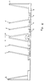
- the storage facility shown in Figure 1 has several movable storage units 1 and fixed at their ends Storage units 2.
- Storage units 1 and 2 are Glass plates 3 set.
- the Storage units 1 and 2 horizontal support surfaces 4 and one relative to the vertical slightly inclined contact surface 5.
- Undercarriage 6 or 8 The undercarriages 6 are in two parallel Rails 7 larger track width used and the trolleys 8th are in two parallel tracks with a smaller track width used.
- the trolleys 8 are accordingly narrower trained so that they in the trolleys 6 larger track width can intervene. The principle of Nesting of the trolleys using FIGS. 7 and 8 are explained.
- Those at the right and left ends of the storage facility fixed bearing units 2 also have a contact surface 4 and a vertical inclined contact surface 5 are leaned against the glass plates 3 to be stored.
- the Inclination direction of the contact surface 5 of the right fixed Bearing unit 2 is opposite to the direction of inclination Contact surface 5 of the movable storage units 1.
- a motor 18 is provided, with the help of which adjacent movable storage unit 1 on the rails of the fixed storage unit 2 pushed away or to this can be brought up.
- the movable bearing units 1 are by means of couplings 10 interconnectable, which can be seen in Figure 2, because there the undercarriages are omitted.
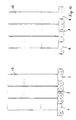
- Figure 2 are the same Parts of the storage facility, which are also shown in Figure 1 are provided with the same reference numerals. As above mentioned, the trolleys of the storage racks 1 are not shown, so that the couplings 10 and their suspensions are recognizable.
- the storage units 1 to Storage of glass plates can be designed in different ways can, as is the case, for example, in FIGS. 3 and 4 is shown.
- FIGS. 3 and 4 With a construction of the storage units 1 after Figure 3 with A-shaped contact surfaces Glass plates from opposite sides to the storage unit 1 ajar.
- the storage unit Contact surface in the direction of travel such a dimension that an extension of the chassis to increase the center distance is not required.
- this setup there is one Tipping safety also because of the A-shaped leaning against each other Glass plates given from the outset.
- the movable storage units 1 for glass storage can in further variants in the most varied of forms, both regarding the contact surfaces as well as the width and Length of the contact surfaces for the glass.
- the moveable 4 can so in a rack system be arranged that on the left side of a plant - In a view according to FIGS. 1 and 2 - located Storage units 1 can be loaded from the right, while on storage units located on the right side can be loaded from the left are. Other variations are possible.
- FIG. 5 Another embodiment of the storage facility, in which a movable driven storage unit 1 in the middle between other movable storage units 1 on their right side and its left side is shown in Fig. 5.
- the movable driven bearing unit is A-shaped trained contact surfaces 5, while the right or moveable storage units 1 on the left Have an L-shaped formation, referring to their horizontal Support surface 4 an inclined to the vertical Contact surface 5 connects.
- the inclination of the contact surface 5 is in the left storage units 1 opposite to that of right storage units 1.
- On the right and left side fixed bearing units 2 are provided. In the 5, the storage units 1 are in a position that on the left between the fixed storage unit 2 and the adjacent one sliding bearing unit 1 a passage is formed.
- FIG. 6 and 7 An embodiment of the couplings 10 is in Figures 6 and 7 shown.
- the couplings 10 have a snap-in Bolt 11, which engages in a locking rod 12, as in Figure 6 is shown.
- the bars 11 have at their free Ends a run-up surface 13, through which they run up the locking rod 12 when pushing the movable Storage units can be lifted up to a push block finally their groove 14 snaps into the locking rod 12, like this is shown in Figure 6.
- the unlocking devices within the floor area under the storage units are preferably at fixed positions at a distance of the couplings that couple the bearing units together.
- a such an arrangement of the unlocking device 14 is shown in FIG. 7 shown, but there are also such unlocking devices in Fig. 2 under the rightmost and leftmost Coupling 10 shown. With such an arrangement it is not necessary for the individual movable storage units to conduct electrical or pneumatic control lines; much more become the electrical or pneumatic control lines in the floor area to those in fixed positions Unlocking devices performed.
- the storage facility shown in Figures 1 and 2 is in the Operated in such a way that in Figure 1 on the right side located storage units 1 first in the direction of the Storage units located on the left side of the storage facility 1 be moved until they couple to it.
- the state at with all the storage units shifted to the left is in figure 2 shown.
- the clutch 10 between them Storage units e.g. pneumatically released and then it becomes uncoupled block of storage units 1 with the help of the drive 18 pulled to the right.
- the left block of the Storage units 1 remain on the left fixed storage unit 2 coupled. Due to the newly formed passage, the can be free accessible storage unit 1 can now be unloaded and loaded.
- the drive device is located on a movable Storage unit in the middle of the storage system as shown in Fig. 5, so when closing a passage at the same time Passage on the other side of the driven bearing unit be opened. This reduces the access time to that goods in stock by half. However, there is a passage on the Side of the driven storage unit 1 to open on the already If there is a passage, the existing passage is first close and then by moving in reverse Direction to open a new passage.
- FIGS. 1, 2 and 4 With storage racks 1, as shown in FIGS. 1, 2 and 4 are shown, in which the contact surface 5 with respect to the Vertical is slightly inclined, the tilting of the Avoid storage racks in that the trolleys 6 and 7 in Travel direction have a dimension so that the wheels 15th or 16 of the chassis 6 or 8 outside the focus of the Storage unit 1 lie.
- Such trolleys are shown in FIGS. 8 and 9.
- the extension of the wheelbase of the Trolleys 6 and 8 can also be seen in FIG. 1. So that movable bearing units 1 despite the extension of the trolleys nevertheless, as close as possible to the Contact surfaces 5 can be pushed together, the trolleys 6 are made smaller than that Trolleys 8 and also run on rails of a smaller number Track width. This can be clearly seen from FIG. 9.
- the Bearing units 1 are alternately with a chassis narrower track width and a chassis wider track width equipped.
- the trolleys can then, as in FIG. 9 is shown, nested together be, with two trolleys when pushed together border the same track width. That way the number of storage units per unit length in Double travel direction.
- the chassis with an extended wheelbase and two different ones Leave widths for two rails of different track width is also advantageous for storage units with a vertical structure Insert 17 as shown in Figure 10. Also in in this case there is a risk of the storage units tipping over significantly reduced.
- the storage units can be superstructures within the allowable limits of the height ratio of the bearing units to the distance of the axes from each other. You can also because of the design of the chassis are pushed together that the superstructures immediately adjoin one another, as can be seen in FIG. 10.
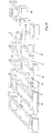
- Fig. 11 is shown in perspective in principle how the Chassis 6 larger track width and the chassis 8 smaller Interlocking track width.
- the contact surfaces 4 have this embodiment for all trolleys the same Width.
- a motor 18 is provided which is the most right drives lying movable storage unit.
- Fig. 12 shows a spindle parallel drive, as in the 11 on the right side between the motor 18 and chassis 8 of the adjacent storage unit is provided.
- the motor 18 drives a spindle 19, either in one or in the other direction.
- a pulley 20 At the end of the spindle is a pulley 20, which also has a belt 21 in one or the other direction.
- the belt 21 engages in two on two undercarriage drive spindles 22, 23 seated pulleys 24, 25 a.
- the threaded landing gear drive spindles move the undercarriage as it rotates.
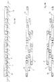
- the interlocking trolleys according to FIG. 13 have three different ones Track widths and allow despite a greatly elongated Center distance for safe guidance of the bearing units Push together to a very short distance.
- the three different track widths of the undercarriage are well based 14 can be seen.
- the running gear of different track widths run on rails of three different track widths. Im pushed together Condition limit two chassis of the same Track width to each other.
- the number of storage units can be varied in different track widths Triple the length of the rail or the length the chassis can with the same storage density on the Extend 1.5 times.
Landscapes
- Engineering & Computer Science (AREA)
- Mechanical Engineering (AREA)
- Warehouses Or Storage Devices (AREA)
- Platform Screen Doors And Railroad Systems (AREA)
Description
Claims (7)
- Lageranlage mit einer Anzahl von geführten, durch eine Antriebsvorrichtung verfahrbaren Lagereinheiten, bei der durch Verfahren von Lagereinheiten ein Durchgang zwischen jeweils zwei Lagereinheiten zum Be- und Entladen einstellbar ist, wobei die Antriebsvorrichtung nur eine der verfahrbaren Lagereinheiten antreibt, und mit jeweils einer zwischen benachbarten Lagereinheiten vorhandenen lösbaren Kupplungsvorrichtung,
dadurch gekennzeichnet,
daß die Lagereinheiten (1) Fahrwerke (6 bzw. 8) aufweisen, deren Achsen in Verfahrrichtung außerhalb der zur Lagerung vorgesehenen Grundfläche liegen und daß die Fahrwerke (6 bzw. 8) nebeneinanderliegender Lagereinheiten zwei verschiedene Spurbreiten aufweisen, wobei das Fahrwerk (8) kleinerer Spurbreite zwischen die Räder des Fahrwerkes (6) größerer Spurbreite verfahrbar ist. - Lageranlage nach Anspruch 1,
dadurch gekennzeichnet,
daß die Lagereinheiten (1) eine gegenüber der Senkrechten geneigte Anlegewand (5) aufweisen, die auf einem Fahrwerk (6 bzw. 8) befestigt ist, dessen Radachsen sich außerhalb der Außenabmessungen der Anlegewand befinden. - Lageranlage nach Anspruch 1 oder 2,
dadurch gekennzeichnet,
daß die Fahrwerke (6,8,26) mit drei verschiedenen Spurbreiten versehen sind, und daß die Fahrwerke auf Schienen dreier verschiedener Spurbreiten laufen und ineinander verschachtelbar sind. - Lageranlage nach Anspruch 1, 2 oder 3,
dadurch gekennzeichnet,
daß die Radachsen der Fahrwerke außerhalb des Schwerpunktes der Lagereinheiten (1) liegen. - Lageranlage nach einem der vorhergehenden Ansprüche,
dadurch gekennzeichnet,
daß lösbare Kupplungsvorrichtungen (10) auf jeder Seite der Fahrwerke (6,8; 6,8,26) derart ausgebildet sind, daß beim Verschieben einer verfahrbaren Lagereinheit (1), die auf der jeweils anderen Seite der Lagereinheit (1 oder 9) vorhandene Kupplung einrastbar ist. - Lageranlage nach Anspruch 5,
dadurch gekennzeichnet,
daß jeder Kupplungsvorrichtung (10) im Ruhezustand der Lagereinheiten an einer festen Position im Boden der Lageranlage eine Entriegelungsvorrichtung (14) gegenüberliegt, die wahlweise zur Entriegelung ansteuerbar ist. - Lageranlage nach Anspruch 11,
dadurch gekennzeichnet,
daß jede Kupplung (10) zwischen den Lagereinheiten (1) eine Hebevorrichtung (14) zur wahlweisen Entriegelung der einrastbaren Riegel (11) aufweist.
Applications Claiming Priority (2)
| Application Number | Priority Date | Filing Date | Title |
|---|---|---|---|
| DE19522528 | 1995-06-23 | ||
| DE19522528A DE19522528C2 (de) | 1995-06-23 | 1995-06-23 | Lageranlage mit einer Anzahl von geführten, durch eine Antriebsvorrichtung verfahrbaren Lagereinheiten |
Publications (3)
| Publication Number | Publication Date |
|---|---|
| EP0749916A2 EP0749916A2 (de) | 1996-12-27 |
| EP0749916A3 EP0749916A3 (de) | 1997-04-09 |
| EP0749916B1 true EP0749916B1 (de) | 2000-01-19 |
Family
ID=7764887
Family Applications (1)
| Application Number | Title | Priority Date | Filing Date |
|---|---|---|---|
| EP96109929A Expired - Lifetime EP0749916B1 (de) | 1995-06-23 | 1996-06-20 | Lageranlage mit einer Anzahl von geführten, durch eine Antriebsvorrichtung verfahrbaren Lagereinheiten |
Country Status (3)
| Country | Link |
|---|---|
| EP (1) | EP0749916B1 (de) |
| AT (1) | ATE188942T1 (de) |
| DE (2) | DE19522528C2 (de) |
Cited By (1)
| Publication number | Priority date | Publication date | Assignee | Title |
|---|---|---|---|---|
| CN108516210A (zh) * | 2018-03-16 | 2018-09-11 | 合肥普发谐利信息科技有限公司 | 一种玻璃包装机构 |
Families Citing this family (14)
| Publication number | Priority date | Publication date | Assignee | Title |
|---|---|---|---|---|
| FR2778897B1 (fr) * | 1998-05-19 | 2000-08-11 | Sigma | Stockeur dynamique, en particulier pour plaques de verre |
| IT1315001B1 (it) * | 2000-05-12 | 2003-01-21 | Antonio Piazza | Magazzino a telai inclinati estraibili per lo stoccaggio e lamovimentazione di prodotti lastriformi. |
| ES2190710B1 (es) * | 2000-10-19 | 2004-11-01 | Tecnocat 21, S.L. | Clasificador automatico para placas de vidrio. |
| CA2460859A1 (en) | 2003-03-13 | 2004-09-13 | Bromer Inc. | Storage system for glass offcuts |
| CA2421121A1 (fr) | 2003-03-13 | 2004-09-13 | Roger Mercure | Dispositif et methode pour la valorisation et l'optimisation de panneaux a decouper |
| ES2255781B1 (es) * | 2003-05-28 | 2007-06-16 | Tecnocat 21, S.L. | Clasificador-almacenador de placas de vidrio, asi como el procedimiento para clasificar y almacenar placas de vidrio. |
| EP1593615A1 (de) | 2004-05-06 | 2005-11-09 | Bystronic Maschinen AG | Lagervorrichtung |
| IT1398455B1 (it) | 2010-02-22 | 2013-02-22 | M B S R L | Magazzino per prodotti laminari. |
| KR20140020869A (ko) * | 2011-01-25 | 2014-02-19 | 웽 성 찬 | 처리 및 운송 시스템 |
| GB2554421A (en) * | 2016-09-27 | 2018-04-04 | Elliott James | A frame for storing and transporting slab materials |
| NO344656B1 (no) * | 2018-08-21 | 2020-03-02 | Espen Wathne | Lagringssystem |
| CN111908128A (zh) * | 2020-08-18 | 2020-11-10 | 衡山兄弟金属制品有限公司 | 一种玻璃加工过程中的转运装置 |
| CN111908129B (zh) * | 2020-08-18 | 2022-04-08 | 衡山兄弟金属制品有限公司 | 一种组装简单的玻璃转运装置 |
| CN113149408A (zh) * | 2021-04-19 | 2021-07-23 | 信义节能玻璃(芜湖)有限公司 | 一种玻璃加工锡退系统 |
Family Cites Families (9)
| Publication number | Priority date | Publication date | Assignee | Title |
|---|---|---|---|---|
| DE7048256U (de) * | 1971-04-29 | Knoebel F & Soehne Kg | Auf Schienen fahrbarer Lagerwagen | |
| AT211228B (de) * | 1958-01-24 | 1960-09-26 | Hans Ingold | Einrichtung zum Lagern von Gegenständen |
| FR2086066B1 (de) * | 1970-04-14 | 1976-12-03 | Brownbuilt Ltd | |
| SU742278A1 (ru) * | 1976-08-01 | 1980-06-25 | Предприятие П/Я В-2620 | Устройство дл хранени длинномерных грузов на складе |
| SU745795A1 (ru) * | 1977-05-19 | 1980-07-07 | Ленинградский Государственный Проектный Институт | Склад дл хранени штучных грузов |
| SE8602154D0 (sv) * | 1986-05-13 | 1986-05-13 | Electrolux Const Ab | Forvaringssystem |
| SU1449482A1 (ru) * | 1987-02-27 | 1989-01-07 | Предприятие П/Я М-5835 | Устройство дл хранени и выдачи грузов |
| DE3831772A1 (de) * | 1987-09-25 | 1989-07-20 | Werner Dipl Ing Roth | Rollregalanlage |
| IT1258617B (it) * | 1992-09-18 | 1996-02-27 | Magazzino a telai mobili a traslazione ortogonale per prodotti di forma piana |
-
1995
- 1995-06-23 DE DE19522528A patent/DE19522528C2/de not_active Expired - Fee Related
-
1996
- 1996-06-20 DE DE59604208T patent/DE59604208D1/de not_active Expired - Lifetime
- 1996-06-20 EP EP96109929A patent/EP0749916B1/de not_active Expired - Lifetime
- 1996-06-20 AT AT96109929T patent/ATE188942T1/de not_active IP Right Cessation
Cited By (2)
| Publication number | Priority date | Publication date | Assignee | Title |
|---|---|---|---|---|
| CN108516210A (zh) * | 2018-03-16 | 2018-09-11 | 合肥普发谐利信息科技有限公司 | 一种玻璃包装机构 |
| CN108516210B (zh) * | 2018-03-16 | 2019-07-19 | 常德中利玻璃门窗有限公司 | 一种玻璃包装机构 |
Also Published As
| Publication number | Publication date |
|---|---|
| DE19522528C2 (de) | 1999-02-18 |
| ATE188942T1 (de) | 2000-02-15 |
| EP0749916A2 (de) | 1996-12-27 |
| DE19522528A1 (de) | 1997-01-09 |
| DE59604208D1 (de) | 2000-02-24 |
| EP0749916A3 (de) | 1997-04-09 |
Similar Documents
| Publication | Publication Date | Title |
|---|---|---|
| DE3213983C2 (de) | Vorrichtung zum Handhaben von Transport- bzw. Lagereinheiten, insbesondere in Hochregal-Blocklagersystemen | |
| DE69127100T2 (de) | Automatische mechanische anlage zum abstellen von objekten, insbesondere von kraftfahrzeugen | |
| EP0458021B1 (de) | Regallager für in selbsttragenden Kassetten aufgenommenes Material | |
| EP0656980B1 (de) | Vorrichtung zum raumsparenden abstellen von kraftfahrzeugen | |
| DE19522528C2 (de) | Lageranlage mit einer Anzahl von geführten, durch eine Antriebsvorrichtung verfahrbaren Lagereinheiten | |
| DE69516697T2 (de) | Eine vorrichtung zum automatischen transport eines fahrzeuges von einem einfahrtbereich zu einem abstellplatz in einer parkgarage | |
| DE3943039A1 (de) | Parkeinrichtung | |
| DE2117922B2 (de) | Lagereinrichtung | |
| DE3535682C2 (de) | Parkvorrichtung für Kraftfahrzeuge | |
| EP0090996B1 (de) | Parkvorrichtung für Kraftfahrzeuge | |
| EP0298341A1 (de) | Regalfördersystem | |
| DE3707395C1 (en) | Return system for rail-bound transport trucks without self-propulsion | |
| EP0583633B1 (de) | Vorrichtung zum Verladen von Kraftfahrzeugen auf Eisenbahnzüge und von Eisenbahnzügen | |
| DE29522338U1 (de) | Lageranlage mit einer Anzahl von geführten, durch eine Antriebsvorrichtung verfahrbaren Lagereinheiten | |
| DE29605501U1 (de) | Lagersystem für Langgutpaletten | |
| DD262221A5 (de) | Kassettenbewegungswerk, insb. zum bewegen von in kassetten untergebrachten stabstahlguetern | |
| DE20008073U1 (de) | Anlage zum Fördern und Lagern von Paletten in einem Gestell | |
| DE3115479A1 (de) | Umsetzvorrichtung fuer ein regalfoerderzeug | |
| DE8210739U1 (de) | Vorrichtung zum Handhaben von Transport- bzw. Lagereinheiten, insbesondere in Hochregal-Blocklagersystemen | |
| DE19613817A1 (de) | Förderwagen für Rollpaletten in einem Blocklager | |
| EP0461735A1 (de) | Regalanlage | |
| DD281212A5 (de) | Vorrichtung zur zentrierung eines bewegbaren laufschienenabschnittes von elektrohaengebahnen | |
| DE3007515A1 (de) | Antriebsvorrichtung, insbesondere fuer parkplatten | |
| DE3800118A1 (de) | Speichereinrichtung insbesondere fuer kraftfahrzeuge | |
| DE4225527C2 (de) | Vorrichtung zum Parken von Kraftfahrzeugen auf Paletten |
Legal Events
| Date | Code | Title | Description |
|---|---|---|---|
| PUAI | Public reference made under article 153(3) epc to a published international application that has entered the european phase |
Free format text: ORIGINAL CODE: 0009012 |
|
| AK | Designated contracting states |
Kind code of ref document: A2 Designated state(s): AT BE CH DE FR GB LI LU NL |
|
| PUAL | Search report despatched |
Free format text: ORIGINAL CODE: 0009013 |
|
| AK | Designated contracting states |
Kind code of ref document: A3 Designated state(s): AT BE CH DE FR GB LI LU NL |
|
| 17P | Request for examination filed |
Effective date: 19970910 |
|
| GRAG | Despatch of communication of intention to grant |
Free format text: ORIGINAL CODE: EPIDOS AGRA |
|
| 17Q | First examination report despatched |
Effective date: 19990319 |
|
| GRAG | Despatch of communication of intention to grant |
Free format text: ORIGINAL CODE: EPIDOS AGRA |
|
| GRAH | Despatch of communication of intention to grant a patent |
Free format text: ORIGINAL CODE: EPIDOS IGRA |
|
| GRAH | Despatch of communication of intention to grant a patent |
Free format text: ORIGINAL CODE: EPIDOS IGRA |
|
| GRAA | (expected) grant |
Free format text: ORIGINAL CODE: 0009210 |
|
| AK | Designated contracting states |
Kind code of ref document: B1 Designated state(s): AT BE CH DE FR GB LI LU NL |
|
| REF | Corresponds to: |
Ref document number: 188942 Country of ref document: AT Date of ref document: 20000215 Kind code of ref document: T |
|
| REG | Reference to a national code |
Ref country code: CH Ref legal event code: NV Representative=s name: E. BLUM & CO. PATENTANWAELTE Ref country code: CH Ref legal event code: EP |
|
| REF | Corresponds to: |
Ref document number: 59604208 Country of ref document: DE Date of ref document: 20000224 |
|
| GBT | Gb: translation of ep patent filed (gb section 77(6)(a)/1977) |
Effective date: 20000322 |
|
| ET | Fr: translation filed | ||
| PLBQ | Unpublished change to opponent data |
Free format text: ORIGINAL CODE: EPIDOS OPPO |
|
| PLBI | Opposition filed |
Free format text: ORIGINAL CODE: 0009260 |
|
| PLBF | Reply of patent proprietor to notice(s) of opposition |
Free format text: ORIGINAL CODE: EPIDOS OBSO |
|
| 26 | Opposition filed |
Opponent name: APB ANTONIO PIAZZA BREVETTI SRL Effective date: 20001016 |
|
| NLR1 | Nl: opposition has been filed with the epo |
Opponent name: APB ANTONIO PIAZZA BREVETTI SRL |
|
| PLBF | Reply of patent proprietor to notice(s) of opposition |
Free format text: ORIGINAL CODE: EPIDOS OBSO |
|
| PLBF | Reply of patent proprietor to notice(s) of opposition |
Free format text: ORIGINAL CODE: EPIDOS OBSO |
|
| PLBF | Reply of patent proprietor to notice(s) of opposition |
Free format text: ORIGINAL CODE: EPIDOS OBSO |
|
| REG | Reference to a national code |
Ref country code: GB Ref legal event code: IF02 |
|
| PLBL | Opposition procedure terminated |
Free format text: ORIGINAL CODE: EPIDOS OPPC |
|
| PLBM | Termination of opposition procedure: date of legal effect published |
Free format text: ORIGINAL CODE: 0009276 |
|
| STAA | Information on the status of an ep patent application or granted ep patent |
Free format text: STATUS: OPPOSITION PROCEDURE CLOSED |
|
| 27C | Opposition proceedings terminated |
Effective date: 20021124 |
|
| NLR2 | Nl: decision of opposition |
Effective date: 20021124 |
|
| PGFP | Annual fee paid to national office [announced via postgrant information from national office to epo] |
Ref country code: LU Payment date: 20040616 Year of fee payment: 9 |
|
| PGFP | Annual fee paid to national office [announced via postgrant information from national office to epo] |
Ref country code: CH Payment date: 20050523 Year of fee payment: 10 |
|
| PG25 | Lapsed in a contracting state [announced via postgrant information from national office to epo] |
Ref country code: LU Free format text: LAPSE BECAUSE OF NON-PAYMENT OF DUE FEES Effective date: 20050620 |
|
| PGFP | Annual fee paid to national office [announced via postgrant information from national office to epo] |
Ref country code: BE Payment date: 20060607 Year of fee payment: 11 |
|
| PG25 | Lapsed in a contracting state [announced via postgrant information from national office to epo] |
Ref country code: LI Free format text: LAPSE BECAUSE OF NON-PAYMENT OF DUE FEES Effective date: 20060630 Ref country code: CH Free format text: LAPSE BECAUSE OF NON-PAYMENT OF DUE FEES Effective date: 20060630 |
|
| REG | Reference to a national code |
Ref country code: CH Ref legal event code: PL |
|
| BERE | Be: lapsed |
Owner name: *HEGLA FAHRZEUG- U. MASCHINENBAU G.M.B.H. & CO. K. Effective date: 20070630 |
|
| PG25 | Lapsed in a contracting state [announced via postgrant information from national office to epo] |
Ref country code: BE Free format text: LAPSE BECAUSE OF NON-PAYMENT OF DUE FEES Effective date: 20070630 |
|
| PGFP | Annual fee paid to national office [announced via postgrant information from national office to epo] |
Ref country code: AT Payment date: 20080624 Year of fee payment: 13 |
|
| PGFP | Annual fee paid to national office [announced via postgrant information from national office to epo] |
Ref country code: NL Payment date: 20080624 Year of fee payment: 13 |
|
| PGFP | Annual fee paid to national office [announced via postgrant information from national office to epo] |
Ref country code: FR Payment date: 20080625 Year of fee payment: 13 |
|
| PGFP | Annual fee paid to national office [announced via postgrant information from national office to epo] |
Ref country code: GB Payment date: 20080625 Year of fee payment: 13 |
|
| GBPC | Gb: european patent ceased through non-payment of renewal fee |
Effective date: 20090620 |
|
| NLV4 | Nl: lapsed or anulled due to non-payment of the annual fee |
Effective date: 20100101 |
|
| REG | Reference to a national code |
Ref country code: FR Ref legal event code: ST Effective date: 20100226 |
|
| PG25 | Lapsed in a contracting state [announced via postgrant information from national office to epo] |
Ref country code: FR Free format text: LAPSE BECAUSE OF NON-PAYMENT OF DUE FEES Effective date: 20090630 |
|
| PG25 | Lapsed in a contracting state [announced via postgrant information from national office to epo] |
Ref country code: GB Free format text: LAPSE BECAUSE OF NON-PAYMENT OF DUE FEES Effective date: 20090620 |
|
| PG25 | Lapsed in a contracting state [announced via postgrant information from national office to epo] |
Ref country code: AT Free format text: LAPSE BECAUSE OF NON-PAYMENT OF DUE FEES Effective date: 20090620 |
|
| PG25 | Lapsed in a contracting state [announced via postgrant information from national office to epo] |
Ref country code: NL Free format text: LAPSE BECAUSE OF NON-PAYMENT OF DUE FEES Effective date: 20100101 |
|
| PGFP | Annual fee paid to national office [announced via postgrant information from national office to epo] |
Ref country code: DE Payment date: 20130814 Year of fee payment: 18 |
|
| REG | Reference to a national code |
Ref country code: DE Ref legal event code: R119 Ref document number: 59604208 Country of ref document: DE |
|
| REG | Reference to a national code |
Ref country code: DE Ref legal event code: R119 Ref document number: 59604208 Country of ref document: DE Effective date: 20150101 |
|
| PG25 | Lapsed in a contracting state [announced via postgrant information from national office to epo] |
Ref country code: DE Free format text: LAPSE BECAUSE OF NON-PAYMENT OF DUE FEES Effective date: 20150101 |