EP0746005A2 - Appareil de commutation électrique - Google Patents
Appareil de commutation électrique Download PDFInfo
- Publication number
- EP0746005A2 EP0746005A2 EP96108421A EP96108421A EP0746005A2 EP 0746005 A2 EP0746005 A2 EP 0746005A2 EP 96108421 A EP96108421 A EP 96108421A EP 96108421 A EP96108421 A EP 96108421A EP 0746005 A2 EP0746005 A2 EP 0746005A2
- Authority
- EP
- European Patent Office
- Prior art keywords
- pendulum
- slide
- switching device
- switching
- articulated
- Prior art date
- Legal status (The legal status is an assumption and is not a legal conclusion. Google has not performed a legal analysis and makes no representation as to the accuracy of the status listed.)
- Granted
Links
Images
Classifications
-
- H—ELECTRICITY
- H01—ELECTRIC ELEMENTS
- H01H—ELECTRIC SWITCHES; RELAYS; SELECTORS; EMERGENCY PROTECTIVE DEVICES
- H01H21/00—Switches operated by an operating part in the form of a pivotable member acted upon directly by a solid body, e.g. by a hand
- H01H21/02—Details
- H01H21/18—Movable parts; Contacts mounted thereon
- H01H21/22—Operating parts, e.g. handle
- H01H21/24—Operating parts, e.g. handle biased to return to normal position upon removal of operating force
- H01H21/245—Operating parts, e.g. handle biased to return to normal position upon removal of operating force the contact returning to its original state upon the next application of operating force
-
- H—ELECTRICITY
- H01—ELECTRIC ELEMENTS
- H01H—ELECTRIC SWITCHES; RELAYS; SELECTORS; EMERGENCY PROTECTIVE DEVICES
- H01H13/00—Switches having rectilinearly-movable operating part or parts adapted for pushing or pulling in one direction only, e.g. push-button switch
- H01H13/50—Switches having rectilinearly-movable operating part or parts adapted for pushing or pulling in one direction only, e.g. push-button switch having a single operating member
- H01H13/56—Switches having rectilinearly-movable operating part or parts adapted for pushing or pulling in one direction only, e.g. push-button switch having a single operating member the contact returning to its original state upon the next application of operating force
Definitions
- the invention relates to an electrical switching device, in particular push button switch, with an actuating element, for. B. rocker switch, which returns to its initial position after actuation, with a slider actuated by it with at least one pendulum articulated thereon and with a switching element which cooperates with the slider and with the pendulum and serves to actuate at least one contact arrangement.
- an electrical switching device in particular push button switch
- an actuating element for. B. rocker switch
- Electrical switching devices are known whose actuating elements, for example rockers, always return to their starting position after a switching operation.
- the switching components acted upon by the actuating element in the relevant switching device retain the respective switching position unchanged until the next actuation.
- the advantage of such an embodiment of an electrical switching device lies in the fact that the overall aesthetic impression of the switching device is not impaired by different inclinations of the actuating element, because this always assumes the same position in the rest position.
- an electrical switching device with a switching mechanism which has an actuating element designed as a rocker, a slide part and a pivotably mounted rocker switch for loading a contact arrangement arranged in a housing base.
- an actuating element designed as a rocker, a slide part and a pivotably mounted rocker switch for loading a contact arrangement arranged in a housing base.
- the slide part with a nose, which rests on a slope formed on the slide part, whereby a force deflection is achieved and the slide part is displaced against the force of a return spring transversely to the direction of actuation of the rocker.
- a swivel part is rotatably supported, the two bearing pins of which each have a flattened portion, against which spring bars resembling leaf springs bear and apply the swivel part to a central position. Furthermore, the swivel part is provided with two pressure pieces arranged symmetrically to one another, which cooperate with the rocker switch, in that it is acted upon by a contact surface formed on each corner of the swivel part facing away from the swivel axis.
- a similar switching device in which the movement of the actuating element of a slide with a beveled pressure surface and at least one pendulum arranged thereon also carries out a transverse movement and thereby also acts on a pivoting switching element, is known on the market as a pushbutton.
- the at least one pivotable pendulum arranged on the slide is designed in the form of an isosceles triangle, whose pivot axis, designed as a plug-in axis, intersects the axis of symmetry of the pendulum near the corner point and is guided in lateral bearing points in the slide.
- the switching element which is also pivotably mounted.
- the switching element takes an inclined position in relation to the pendulum, so that depending on the respective switching position, the pendulum when pressed with one of the two other corner points against the Slides butts, experiences a certain deflection and brings the slider into its other position.
- a compression spring supported on the slide ensures that the pendulum always takes a central position between the two deflection positions at rest.
- a disadvantage of this design has been shown to be a certain susceptibility to contamination, for example due to dust, and the resulting stiffness of this switching system.
- the penetration of dust can never be completely ruled out, which settles at the bearing points and can sometimes lead to incorrect actuation due to insufficient pivoting of the pendulum due to excessive bearing friction.
- the assembly of the known switching device is time-consuming and part-related in terms of storage and adjustment of the pendulum.
- the pendulum automatically returns to its rest position after each actuation.
- the rest position is a middle position between two opposing deflections.
- a preferred development of the invention provides that the pendulum and the slide are made of plastic. This enables cost-effective series production while at the same time taking advantage of weight advantages compared to manufacturing from metal.
- a preferred embodiment provides is characterized in that the articulated connection of the pendulum with the slide is web-like and has a connection cross-section which is dimensioned such that, using the elasticity of the material used, the restoring force required to reset the pendulum when the pendulum is deflected results. In other words, depending on the restoring force determined or determined as necessary, this can be varied between strong and weak restoring simply by changing the connection cross section of the pendulum to the slide.
- a special embodiment is characterized in that a film hinge is provided as the articulated connection of the pendulum with the slide.
- two pendulums can be provided, which are arranged symmetrically to one another at a distance from the longitudinal axis of the slide.
- the pendulum is expediently embodied as a flat part, on the end of which, remote from the articulated connection, there are formed or molded parts which cooperate with the switching element in order to act on it.
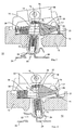
- Fig. 1 is a partial longitudinal section through a switching device 10 according to the invention with a base upper part 12, in which a switching element 14 is pivotally mounted and cooperates with a slide 16, which is operatively connected to an actuating element 18 via a nose 19 molded thereon with a on the slide 16 molded switch bevel 17 is operatively connected.
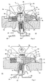
- a triangular swivel part generally referred to as a pendulum 20, which transmits the movement of the slider 16 to the switching element 14, which in turn actuates a contact arrangement 22 which has a fixed contact piece 24 and a movable contact piece 26 which is on a Contact carrier 28 is pivotally supported and can be pivoted from the closed position shown in FIG. 1 to the open position shown in FIG. 2.
- the switching element 14 whose known pivot bearing is not shown in detail here and which acts on the movable contact piece 26 with a spring sleeve against the contact carrier 28, has at its end facing away from the contact arrangement 22 a transverse to its longitudinal axis, the switching element penetrating recess 15 , which is penetrated by the slide 16, which in turn acts on a return spring 30, which assumes the rest position shown in Fig. 1.
- the pendulum 20 which is similar to an isosceles triangle, is connected in one piece to the slide 16 via a small connecting web 21.
- This web-like connection 21 of the pendulum 20 with the slider 16 serves simultaneously as a swivel joint for the pendulum, the swivel path of the pendulum 20 on the one hand and, on the other hand, the restoring force resulting from its deflection is determined both by the elasticity of the material used and by the cross section of the connecting web 21 that is provided in the design.
- the horizontally oriented pendulum 20 engages with its upper symmetry half 32 in engagement with a switching web 34 formed on the switching element 14, which forms the upper limit of the recess 15, and thus transmits the displacement of the slide 16 to the switching element 14, the then pivots counterclockwise about its axis of rotation intersecting with the central axis of the slide 16.
- the switching element 14 After reaching the end position of the slide 16 shown in FIG. 2, the switching element 14 assumes the switching position according to FIG. 2, in which the contact arrangement 22 is opened due to the action that is thereby taken.
- the main advantage of the present invention results from the fact that, on the one hand, the manufacture of the switching device according to the invention is considerably simplified, since fewer parts are to be assembled, and, secondly, what is even more significant, interferences due to excessive friction due to dust contamination, the pivoting mobility of the pendulum 20 do not affect, since the pendulum is integrally molded onto the slide 16.
- the connection cross section in the form of a web 21 it is also possible to adjust the restoring force of the pendulum 20.
- connection cross section is either above or below the end section of the web 16, which is designed as a flat web, to which the pendulum 20 then adjoins at an angle, or else the spring action results from a torsion of the connecting web connecting the end face of the end section of the pendulum 16 shown here here .
- the angle between the direction of movement of the slide 16 and the central position of the switching element 14 is 90 ° in the example shown.
- this angle can be between 0 ° and ⁇ 90 °, that is to say that the contact point 22 to be actuated is arranged between the slide 16 and the actuating element 18, so that the switching element is directed quasi upwards, that is to say Actuation side.
Landscapes
- Slide Switches (AREA)
- Mechanisms For Operating Contacts (AREA)
- Control Of Throttle Valves Provided In The Intake System Or In The Exhaust System (AREA)
- Lock And Its Accessories (AREA)
- Valve Device For Special Equipments (AREA)
- Tumbler Switches (AREA)
- Electrical Discharge Machining, Electrochemical Machining, And Combined Machining (AREA)
- Control Of Electric Motors In General (AREA)
- Control Of Motors That Do Not Use Commutators (AREA)
- Push-Button Switches (AREA)
Applications Claiming Priority (2)
| Application Number | Priority Date | Filing Date | Title |
|---|---|---|---|
| DE19520239 | 1995-06-02 | ||
| DE19520239A DE19520239A1 (de) | 1995-06-02 | 1995-06-02 | Elektrisches Schaltgerät |
Publications (3)
| Publication Number | Publication Date |
|---|---|
| EP0746005A2 true EP0746005A2 (fr) | 1996-12-04 |
| EP0746005A3 EP0746005A3 (fr) | 1998-05-06 |
| EP0746005B1 EP0746005B1 (fr) | 2002-03-06 |
Family
ID=7763493
Family Applications (1)
| Application Number | Title | Priority Date | Filing Date |
|---|---|---|---|
| EP96108421A Expired - Lifetime EP0746005B1 (fr) | 1995-06-02 | 1996-05-28 | Appareil de commutation électrique |
Country Status (3)
| Country | Link |
|---|---|
| EP (1) | EP0746005B1 (fr) |
| AT (1) | ATE214197T1 (fr) |
| DE (2) | DE19520239A1 (fr) |
Cited By (1)
| Publication number | Priority date | Publication date | Assignee | Title |
|---|---|---|---|---|
| CN101840807A (zh) * | 2009-03-12 | 2010-09-22 | Abb股份公司 | 电气安装设备的开关模块 |
Families Citing this family (1)
| Publication number | Priority date | Publication date | Assignee | Title |
|---|---|---|---|---|
| DE19817097B4 (de) * | 1998-04-17 | 2005-06-02 | Abb Patent Gmbh | Monostabiles elektrisches Installationsschaltgerät |
Family Cites Families (5)
| Publication number | Priority date | Publication date | Assignee | Title |
|---|---|---|---|---|
| DE2548674C3 (de) * | 1975-10-30 | 1982-11-11 | Paul Hochköpper & Co, 5880 Lüdenscheid | Elektrischer Tastschalter |
| US5047598A (en) * | 1987-10-28 | 1991-09-10 | Mcgill Manufacturing Company, Inc. | Safety rocker with improved actuator mounting |
| DE3912798A1 (de) * | 1989-04-19 | 1990-10-25 | Jung Gmbh Albrecht | Schaltmechanik fuer einen tastschalter |
| DE4042219C1 (fr) * | 1990-12-29 | 1992-04-23 | Abb Patent Gmbh, 6800 Mannheim, De | |
| DE4124594A1 (de) * | 1991-07-25 | 1993-01-28 | Kostal Leopold Gmbh & Co Kg | Elektrischer schalter |
-
1995
- 1995-06-02 DE DE19520239A patent/DE19520239A1/de not_active Withdrawn
-
1996
- 1996-05-28 DE DE59608820T patent/DE59608820D1/de not_active Expired - Fee Related
- 1996-05-28 EP EP96108421A patent/EP0746005B1/fr not_active Expired - Lifetime
- 1996-05-28 AT AT96108421T patent/ATE214197T1/de not_active IP Right Cessation
Cited By (4)
| Publication number | Priority date | Publication date | Assignee | Title |
|---|---|---|---|---|
| CN101840807A (zh) * | 2009-03-12 | 2010-09-22 | Abb股份公司 | 电气安装设备的开关模块 |
| EP2228811A3 (fr) * | 2009-03-12 | 2013-01-09 | Abb Ag | Insert de commutateur d'un appareil d'installation électrique |
| CN101840807B (zh) * | 2009-03-12 | 2014-03-26 | Abb股份公司 | 电气安装设备的开关模块 |
| RU2513860C2 (ru) * | 2009-03-12 | 2014-04-20 | Абб Аг | Переключающая вставка электрического инсталляционного прибора |
Also Published As
| Publication number | Publication date |
|---|---|
| EP0746005B1 (fr) | 2002-03-06 |
| DE59608820D1 (de) | 2002-04-11 |
| DE19520239A1 (de) | 1996-12-05 |
| EP0746005A3 (fr) | 1998-05-06 |
| ATE214197T1 (de) | 2002-03-15 |
Similar Documents
| Publication | Publication Date | Title |
|---|---|---|
| DE69314768T2 (de) | Öffnungsvorrichtung einer kappe | |
| DE2356024A1 (de) | Tastenbrett | |
| DE2510902C3 (de) | Elektrischer Schalter | |
| DE3405654A1 (de) | Betaetigungsvorrichtung fuer schalteinrichtungen | |
| EP0743664B1 (fr) | Appareil de commutation électrique | |
| DE3336877A1 (de) | Elektrischer schnappschalter | |
| DE2815888C2 (de) | Druckabhängiger Schalter | |
| DE3912798C2 (fr) | ||
| DE2904899C2 (de) | Elektrischer Schalter | |
| DE3604014C2 (fr) | ||
| DE2612160A1 (de) | Staubsaugermundstueck mit zwei alternativ verwendbaren werkzeugen | |
| EP0746005B1 (fr) | Appareil de commutation électrique | |
| DE3126816C2 (fr) | ||
| DE4326312A1 (de) | Kippschalter mit Anschlag zur Geräuschdämpfung | |
| DE2732723C2 (de) | Elektrische Schaltvorrichtung | |
| DE2853810B1 (de) | Druckknopftaster | |
| DE19629006A1 (de) | Schnappschalter mit verstärktem Druckpunkt | |
| DE3402082A1 (de) | Elektrischer schnappschalter | |
| DE2940174C2 (de) | Elektrischer Schalter, insbesondere für Kraftfahrzeuge | |
| DE3638834A1 (de) | Drueckverriegelungsvorrichtung | |
| DE29802820U1 (de) | Vorrichtung für das Ein- und Ausschalten eines Elektromotors, insbesondere eines Elektrowerkzeugs | |
| DE3412377C2 (fr) | ||
| DE2911252C2 (de) | Schnappschalter mit Kontaktbrücken | |
| DE4239965C2 (de) | Elektrische Schaltvorrichtung | |
| DE4220134A1 (de) | Großflächige Kurzhubtaste |
Legal Events
| Date | Code | Title | Description |
|---|---|---|---|
| PUAI | Public reference made under article 153(3) epc to a published international application that has entered the european phase |
Free format text: ORIGINAL CODE: 0009012 |
|
| AK | Designated contracting states |
Kind code of ref document: A2 Designated state(s): AT DE ES FI GR NL SE |
|
| PUAL | Search report despatched |
Free format text: ORIGINAL CODE: 0009013 |
|
| AK | Designated contracting states |
Kind code of ref document: A3 Designated state(s): AT DE ES FI GR NL SE |
|
| 17P | Request for examination filed |
Effective date: 19980522 |
|
| 17Q | First examination report despatched |
Effective date: 20010116 |
|
| GRAG | Despatch of communication of intention to grant |
Free format text: ORIGINAL CODE: EPIDOS AGRA |
|
| GRAG | Despatch of communication of intention to grant |
Free format text: ORIGINAL CODE: EPIDOS AGRA |
|
| GRAH | Despatch of communication of intention to grant a patent |
Free format text: ORIGINAL CODE: EPIDOS IGRA |
|
| GRAH | Despatch of communication of intention to grant a patent |
Free format text: ORIGINAL CODE: EPIDOS IGRA |
|
| RAP1 | Party data changed (applicant data changed or rights of an application transferred) |
Owner name: ABB PATENT GMBH |
|
| GRAA | (expected) grant |
Free format text: ORIGINAL CODE: 0009210 |
|
| AK | Designated contracting states |
Kind code of ref document: B1 Designated state(s): AT DE ES FI GR NL SE |
|
| PG25 | Lapsed in a contracting state [announced via postgrant information from national office to epo] |
Ref country code: NL Free format text: LAPSE BECAUSE OF FAILURE TO SUBMIT A TRANSLATION OF THE DESCRIPTION OR TO PAY THE FEE WITHIN THE PRESCRIBED TIME-LIMIT Effective date: 20020306 Ref country code: GR Free format text: LAPSE BECAUSE OF FAILURE TO SUBMIT A TRANSLATION OF THE DESCRIPTION OR TO PAY THE FEE WITHIN THE PRESCRIBED TIME-LIMIT Effective date: 20020306 Ref country code: FI Free format text: LAPSE BECAUSE OF FAILURE TO SUBMIT A TRANSLATION OF THE DESCRIPTION OR TO PAY THE FEE WITHIN THE PRESCRIBED TIME-LIMIT Effective date: 20020306 |
|
| REF | Corresponds to: |
Ref document number: 214197 Country of ref document: AT Date of ref document: 20020315 Kind code of ref document: T |
|
| REF | Corresponds to: |
Ref document number: 59608820 Country of ref document: DE Date of ref document: 20020411 |
|
| PG25 | Lapsed in a contracting state [announced via postgrant information from national office to epo] |
Ref country code: AT Free format text: LAPSE BECAUSE OF NON-PAYMENT OF DUE FEES Effective date: 20020528 |
|
| PG25 | Lapsed in a contracting state [announced via postgrant information from national office to epo] |
Ref country code: SE Free format text: LAPSE BECAUSE OF FAILURE TO SUBMIT A TRANSLATION OF THE DESCRIPTION OR TO PAY THE FEE WITHIN THE PRESCRIBED TIME-LIMIT Effective date: 20020606 |
|
| NLV1 | Nl: lapsed or annulled due to failure to fulfill the requirements of art. 29p and 29m of the patents act | ||
| PG25 | Lapsed in a contracting state [announced via postgrant information from national office to epo] |
Ref country code: ES Free format text: LAPSE BECAUSE OF FAILURE TO SUBMIT A TRANSLATION OF THE DESCRIPTION OR TO PAY THE FEE WITHIN THE PRESCRIBED TIME-LIMIT Effective date: 20020925 |
|
| PGFP | Annual fee paid to national office [announced via postgrant information from national office to epo] |
Ref country code: DE Payment date: 20021227 Year of fee payment: 8 |
|
| PLBE | No opposition filed within time limit |
Free format text: ORIGINAL CODE: 0009261 |
|
| STAA | Information on the status of an ep patent application or granted ep patent |
Free format text: STATUS: NO OPPOSITION FILED WITHIN TIME LIMIT |
|
| 26N | No opposition filed |
Effective date: 20021209 |
|
| PG25 | Lapsed in a contracting state [announced via postgrant information from national office to epo] |
Ref country code: DE Free format text: LAPSE BECAUSE OF NON-PAYMENT OF DUE FEES Effective date: 20041201 |