EP0745878A2 - Varioobjektiv mit Fokussierung durch das hintere Linsenglied - Google Patents
Varioobjektiv mit Fokussierung durch das hintere Linsenglied Download PDFInfo
- Publication number
- EP0745878A2 EP0745878A2 EP96108501A EP96108501A EP0745878A2 EP 0745878 A2 EP0745878 A2 EP 0745878A2 EP 96108501 A EP96108501 A EP 96108501A EP 96108501 A EP96108501 A EP 96108501A EP 0745878 A2 EP0745878 A2 EP 0745878A2
- Authority
- EP
- European Patent Office
- Prior art keywords
- lens unit
- lens
- refractive power
- zoom lens
- zoom
- Prior art date
- Legal status (The legal status is an assumption and is not a legal conclusion. Google has not performed a legal analysis and makes no representation as to the accuracy of the status listed.)
- Granted
Links
Images


Classifications
-
- G—PHYSICS
- G02—OPTICS
- G02B—OPTICAL ELEMENTS, SYSTEMS OR APPARATUS
- G02B15/00—Optical objectives with means for varying the magnification
- G02B15/14—Optical objectives with means for varying the magnification by axial movement of one or more lenses or groups of lenses relative to the image plane for continuously varying the equivalent focal length of the objective
- G02B15/16—Optical objectives with means for varying the magnification by axial movement of one or more lenses or groups of lenses relative to the image plane for continuously varying the equivalent focal length of the objective with interdependent non-linearly related movements between one lens or lens group, and another lens or lens group
- G02B15/163—Optical objectives with means for varying the magnification by axial movement of one or more lenses or groups of lenses relative to the image plane for continuously varying the equivalent focal length of the objective with interdependent non-linearly related movements between one lens or lens group, and another lens or lens group having a first movable lens or lens group and a second movable lens or lens group, both in front of a fixed lens or lens group
- G02B15/167—Optical objectives with means for varying the magnification by axial movement of one or more lenses or groups of lenses relative to the image plane for continuously varying the equivalent focal length of the objective with interdependent non-linearly related movements between one lens or lens group, and another lens or lens group having a first movable lens or lens group and a second movable lens or lens group, both in front of a fixed lens or lens group having an additional fixed front lens or group of lenses
- G02B15/173—Optical objectives with means for varying the magnification by axial movement of one or more lenses or groups of lenses relative to the image plane for continuously varying the equivalent focal length of the objective with interdependent non-linearly related movements between one lens or lens group, and another lens or lens group having a first movable lens or lens group and a second movable lens or lens group, both in front of a fixed lens or lens group having an additional fixed front lens or group of lenses arranged +-+
-
- G—PHYSICS
- G02—OPTICS
- G02B—OPTICAL ELEMENTS, SYSTEMS OR APPARATUS
- G02B15/00—Optical objectives with means for varying the magnification
- G02B15/14—Optical objectives with means for varying the magnification by axial movement of one or more lenses or groups of lenses relative to the image plane for continuously varying the equivalent focal length of the objective
- G02B15/145—Optical objectives with means for varying the magnification by axial movement of one or more lenses or groups of lenses relative to the image plane for continuously varying the equivalent focal length of the objective having five groups only
- G02B15/1451—Optical objectives with means for varying the magnification by axial movement of one or more lenses or groups of lenses relative to the image plane for continuously varying the equivalent focal length of the objective having five groups only the first group being positive
- G02B15/145113—Optical objectives with means for varying the magnification by axial movement of one or more lenses or groups of lenses relative to the image plane for continuously varying the equivalent focal length of the objective having five groups only the first group being positive arranged +-++-
Definitions
- This invention relates to zoom lenses of the rear focus type and, more particularly, to a high-range, large relative aperture zoom lens of the rear focus type whose variable magnification ratio is about 10 and whose F-number is about 1.8 at the wide-angle end, which is adapted for use in photographic cameras, video cameras or broadcasting cameras.
- zoom lenses of a type in which a lens unit other than the front or first lens unit is made movable to effect focusing i.e., of the so-called "rear focus" type.
- a zoom lens of the rear focus type has such advantages that the effective diameter of the first lens unit becomes smaller so as to easily improve the compact form of the entire lens system, that a close-up photography, particularly, a supershort focusing, can be performed with ease, and further that, since a lens unit to be used for focusing is smaller in size and lighter in weight, a weaker driving torque suffices for moving the lens unit and a rapid focus adjustment, therefore, can be performed.
- Such a zoom lens of the rear focus type is disclosed in, for example, Japanese Laid-Open Patent Applications Nos. Sho 62-24213 and Sho 63-247316, in which the zoom lens comprises, in order from an object side, a first lens unit of positive refractive power, a second lens unit of negative refractive power, a third lens unit of positive refractive power and a fourth lens unit of positive refractive power, totalling four lens units, the second lens unit is moved to vary magnification, and the fourth lens unit is moved to compensate for the image shift caused by the variation of magnification and to effect focusing.
- a zoom lens comprises, in order from an object side, a first lens unit of positive refractive power, a second lens unit of negative refractive power, a third lens unit of positive refractive power and a fourth lens unit of positive refractive power, wherein the third lens unit is constructed with a positive lens and a negative lens in the form of the telephoto type, thus shortening the overall length of the third and fourth lens units.
- a zoom lens comprises, in order from an object side, a first lens unit of positive refractive power, a second lens unit of negative refractive power, a third lens unit of positive refractive power, a fourth lens unit of positive refractive power and a fifth lens unit of negative refractive power, the second and fourth lens units being moved to vary magnification and the fourth lens unit being moved to effect focusing, wherein the overall length of the third, fourth and fifth lens units is shortened owing to the use of the negative fifth lens unit.
- the use of the rear focus type in the zoom lens produces the outstanding advantages described before. That is, the entirety of the lens system is minimized in bulk and size. Rapid focusing becomes possible. Further, a close-up photography becomes easier to do.
- a zoom lens comprising, in order from an object side, a first lens unit of positive refractive power, a second lens unit of negative refractive power, a third lens unit of positive refractive power and a fourth lens unit of positive refractive power, if it is attempted to shorten the overall length of the third and fourth lens units by increasing a refractive power of the third lens unit, the amount of movement of the fourth lens unit during focusing or during variation of magnification becomes too large. For an object at the minimum distance, therefore, a problem arose in that, as zooming to the intermediate region of focal lengths, the third and fourth lens units mechanically interfere with each other. Thus, the air separation between the third and fourth lens units has to be widened greatly, and the total length is caused to become rather longer.
- the zoom lens disclosed in Japanese Laid-Open Patent Application No. Hei 4-301612 is a 5-unit one in which a stationary negative lens is additionally provided on the image side of the four lens units.
- the third to fourth lens units are formed to the telephoto type, thereby shortening the total length of the entire lens system.
- an aperture stop is located in between the second and third lens units, it is necessary to excessively widen the space where a light beam strongly diverges behind the second lens unit.
- this arrangement leads to an increase in the variation of aberrations during variation of magnification or during focusing. It is, therefore, very difficult to simultaneously fulfill the requirements of achieving improvements of the compact form and of maintaining a good stability of high optical performance throughout.
- the invention employs the rear focusing method and is to greatly increase the relative aperture and the zooming range at once.
- An object of the invention is, therefore, to provide a zoom lens of the rear focus type with the total length of the entire system shortened to improve the compact form, while still permitting a good stability of optical performance to be maintained at a high level throughout the entire zooming range and throughout the entire focusing range.
- a zoom lens according to the invention comprises, in order from an object side to an image side, a first lens unit having a positive refractive power, a second lens unit having a negative refractive power, a third lens unit having a positive refractive power, a fourth lens unit having a positive refractive power and a fifth lens unit having a negative refractive power, wherein at least the second and fourth lens units are moved to vary magnification and the fourth lens unit is moved to effect focusing, and wherein an aperture stop is located in a space between the third and fourth lens units.
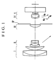
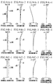
- Fig. 1 is a lens block diagram of numerical examples 1 and 2 of the invention.
- Fig. 2 is a lens block diagram of a numerical example 3 of the invention.
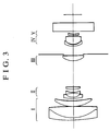
- Fig. 3 is a lens block diagram of a numerical example 4 of the invention.
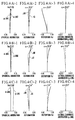
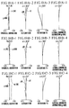
- Figs. 4(A)-1 to 4(A)-4, Figs. 4(B)-1 to 4(B)-4 and Figs. 4(C)-1 to 4(C)-4 are graphic representations of the aberrations of the zoom lens of the numerical example 1.
- Figs. 5(A)-1 to 5(A)-4, Figs. 5(B)-1 to 5(B)-4 and Figs. 5(C)-1 to 5(C)-4 are graphic representations of the aberrations of the zoom lens of the numerical example 2.
- Figs. 6(A)-1 to 6(A)-4, Figs. 6(B)-1 to 6(B)-4 and Figs. 6(C)-1 to 6(C)-4 are graphic representations of the aberrations of the zoom lens of the numerical example 3.
- Figs. 7(A)-1 to 7(A)-4, Figs. 7(B)-1 to 7(B)-4 and Figs. 7(C)-1 to 7(C)-4 are graphic representations of the aberrations of the zoom lens of the numerical example 4.
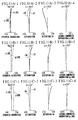
- Fig. 8 is a lens block diagram of numerical examples 5 to 7 of the invention.
- Figs. 9(A)-1 to 9(A)-4, Figs. 9(B)-1 to 9(B)-4 and Figs. 9(C)-1 to 9(C)-4 are graphic representations of the aberrations of the zoom lens of the numerical example 5.
- Figs. 10(A)-1 to 10(A)-4, Figs. 10(B)-1 to 10(B)-4 and Figs. 10(C)-1 to 10(C)-4 are graphic representations of the aberrations of the zoom lens of the numerical example 6.
- Figs. 11(A)-1 to 11(A)-4, Figs. 11(B)-1 to 11(B)-4 and Figs. 11(C)-1 to 11(C)-4 are graphic representations of the aberrations of the zoom lens of the numerical example 7.
- I denotes the first lens unit, II the second lens unit, III the third lens unit, IV the fourth lens unit and V the fifth lens unit.
- ⁇ M stands for the meridional image focus
- ⁇ S for the sagittal image focus
- d for the spectral d-line
- g for the spectral g-line.
- Fig. 1 is a longitudinal section view showing the numerical examples 1 and 2 of zoom lenses of the invention, in which roman numeral I denotes the first lens unit of positive refractive power, roman numeral II denotes the second lens unit of negative refractive power, roman numeral III denotes the third lens unit of positive refractive power, roman numeral IV denotes the fourth lens unit of positive refractive power and roman numeral V denotes the fifth lens unit of negative refractive power.
- the ones of each figure number with suffix (A), (B) or (C) show the aberrations in the wide-angle end, an intermediate focal length position, or the telephoto end, respectively.
- At least the second lens unit is moved toward the image side as shown by the arrow, while the fourth lens unit is simultaneously moved to compensate for the shift of an image plane caused by the variation of magnification.
- the fourth lens unit is moved along an optical axis to effect focusing, as the rear focus type is employed.
- the fourth lens unit is moved to compensate for the image shift along a locus shown by a solid line curve 4a, or a dashed line curve 4b, respectively, in Fig. 1.
- first, third and fifth lens units remain stationary during variation of magnification and during focusing.
- At least the first lens unit may be also moved in order to lessen the duty of varying magnification that the second lens unit bears.
- the fourth lens unit that is given not only the function of compensating for the image shift with zooming but also the focusing function.
- the loci of motion of the fourth lens unit are made convex toward the object side during variation of magnification from the wide-angle end to the telephoto end. This assures efficient utilization of the air space between the third lens unit and the fourth lens unit, thus achieving a shortening of the total length of the entire lens system advantageously.
- the fourth lens unit is moved forward as shown by a straight line 4c in Fig. 1.
- an aperture stop SP for determining the F-number which would be located in the space between the second and third lens units according to the prior art, is located in the space between the third and fourth lens units according to the invention. This leads to efficient utilization of the space, thus reducing the curvature of field from that which would be otherwise produced due to the increase of the Petzval sum when the overall length of the third to fifth lens units is shortened.
- the aperture stop is positioned in the space between the third and fourth lens units, to allow for reduction of the separation between the second and third lens units.
- the space between the third and fourth lens units is widened to lessen the negative increase of the Petzval sum resulting from the decrease of the distance from the third lens unit to the image plane. The field curvature is thus corrected well when the total length of the entire lens system is shortened.
- the following condition is satisfied as to a relationship between an air separation D 23 between a lens surface nearest to the image side of the second lens unit and a lens surface nearest to the object side of the third lens unit for an infinitely distant object in the telephoto end and a focal length f W of the entire zoom lens: 0.04 ⁇ D 23 /f W ⁇ 0.21
- This condition gives an appropriate range for the separation between the second and third lens units to facilitate the shortening of the total length of the complete zoom lens.
- the distance D S between a lens surface nearest to the image side of the third lens unit and the aperture stop in the wide-angle end falls in the following range: 0.11 ⁇ D S /f W ⁇ 0.45
- the shortening of the total length of the complete zoom lens is thus effectively performed without affecting the operation of the diaphragm blades of the aperture stop.
- the lens surface and the aperture stop become so close to each other as to produce a possibility of occurrence of the mechanical interference of the aperture stop with the lens surface when the diaphragm blades are taken out of flatness, or like accident occurs. So, it should be avoided.
- a magnification ⁇ 5 for an infinitely distant object of the fifth lens unit is determined so as to satisfy the following condition: 1.2 ⁇ ⁇ 5 ⁇ 2.0 The optical performance is thus preserved while shortening the total length of the complete zoom lens.
- f 3 is a focal length of the third lens unit
- f W is a focal length in the wide-angle end of the entire zoom lens.
- condition (4) give a proper range for the focal length of the third lens unit.
- the lower limit is exceeded, as this means that the refractive power of the third lens unit is too strong, it is in some cases that insufficient correction of spherical aberration and coma results. In other cases, it becomes difficult to secure the back focal distance.
- the shortening of the overall length of the third to fifth lens units is relied on the minimization of the movement of the fourth lens unit.
- condition (5) give a proper range for the focal length of the fourth lens unit.
- the lower limit is exceeded, as this means that the refractive power of the fourth lens unit is too strong, a large variation of spherical aberration during variation of magnification results.
- the upper limit is exceeded, the movement of the fourth lens unit becomes so much longer that a sufficient effect of shortening the total length of the complete zoom lens is not produced due to the necessity for widening the air separation between the third and fourth lens units.
- the shortening of the lens length of a zoom section contributes to a further shortening of the total length of the complete zoom lens.
- the inequalities of condition (6) are concerned with the refractive power of the second lens unit and have an aim to obtain a predetermined variable magnification ratio advantageously in such a manner that the aberrations are maintained stable against zooming.
- the number of lens elements is reduced.
- aspheric surfaces are preferably introduced to some of the lens units, particularly, the third and fourth lens units.
- the third lens unit is constructed in the form of a single lens having at least one aspheric surface and the fourth lens unit is constructed with a negative meniscus lens and a positive lens, totaling two lenses.
- a negative lens of the first lens unit is made up by using a glass material whose Abbe number ⁇ 1N lies within the following range: ⁇ 1N ⁇ 23
- the first lens unit is, as a rule, constructed with a plus-minus cemented lens and a positive meniscus lens. As shown in the numerical example 3, however, the cemented lens may be made up in broken contact. The resulting air space between its positive and negative lenses shifts the rear principal point of the first lens unit toward the second lens unit, thereby reducing the interval between the first and second lens units. Even with this, when to increase the maximum field angle, it is also possible to suppress the resultant increase of the diameter of the front lens members to a minimum, provided that the real separation between the first and second lens unit is kept to be the same.
- the negative cemented lens of the second lens unit may be divided into two lenses or negative and positive lenses to increase the degree of freedom on the aberration correction.
- Ri is the radius of curvature of the i-th lens surface, when counted from the object side
- Di is the i-th axial thickness or air separation, when counted from the object side
- Ni and ⁇ i are respectively the refractive index and Abbe number of the glass of the i-th lens element when counted from the object side.
- the last two surfaces define a face plate or like glass material.
- the notation "e-0X" means 10 -x .
- a zoom lens comprises, in order from an object side, a first lens unit L1 of positive refractive power, a second lens unit L2 of negative refractive power, a third lens unit L3 of positive refractive power, a fourth lens unit L4 of positive refractive power and a fifth lens unit L5 of negative refractive power.
- An aperture stop SP is located in the space between the third lens unit L3 and the fourth lens unit L4.
- FP stands for the Focal Plane.
- the second lens unit is axially moved toward the image side as shown by the arrow, while the fourth lens unit is moved to compensate for the image shift caused by the variation of magnification. Focusing is performed by axially moving the fourth lens unit. That is, the rear focus type is employed.
- a solid line curve 4a and a dashed line curve 4b for the fourth lens unit in Fig. 8 show the loci of motion required to compensate for the image shift during zooming with an object at infinity and the minimum distance, respectively. It is to be noted that the first, third and fifth lens units remain stationary during variation of magnification and during focusing.
- the fourth lens unit for compensating for the image shift with zooming is given also the focusing function, its zooming movement from the wide-angle end to the telephoto end is made, in particular, to depict a locus convex toward the object side as shown by the curves 4a and 4b in Fig. 8.
- the space between the third and fourth lens units is thus efficiently used to achieve a shortening of the total length of the complete zoom lens advantageously.
- the fourth lens unit is moved forward as shown by a straight line 4c in Fig. 8.
- the first lens unit may be made to move forward as zooming goes from the wide-angle end to the telephoto end. If so, the contribution of the second lens unit to the variation of the focal length is diminished to effect a favorable result on the aberration correction.
- a condition is set forth for the distance TD from the first lens surface nearest to the object side to a paraxial image plane, as follows: 0.8 ⁇ TD/f T ⁇ 1.0 where f T is a focal length in the telephoto end of the entire zoom lens.
- the aperture stop SP is located in the space between the third lens unit L3 and the fourth lens unit L4.
- Such an efficient utilization of the space permits minimization of the produced amount of field curvature which would otherwise increase due to the increase of the Petzval sum when the overall length of the third to fifth lens units is shortened.
- the negative refractive power of the negative fifth lens unit has to be so much increased to increase the telephoto ratio to even higher a value.
- the Petzval sum of the entire lens system which has increased due to the strengthening of the refractive power of the second lens unit is then further increased in the negative sense. As a result, it becomes difficult to correct field curvature, particularly, the sagittal one.
- the aperture stop SP is located in the space between the third and fourth lens units to allow for reduction of the separation between the second and third lens units.
- the space between the third and fourth lens units is widened to lessen the negative increase of the Petzval sum resulting from the decrease of the distance from the third lens unit to the image plane. The field curvature is thus corrected well when the total length of the complete zoom lens is shortened.
- the invention has set forth the rules of design for the various parameters as described above to simultaneously fulfill the requirements of improving the compact form of the entire lens system and of correcting all aberrations well. To secure an even better optical performance, it is preferred to satisfy at least one of the following conditions:
- Ri is the radius of curvature of the i-th lens surface, when counted from the object side
- Di is the i-th axial thickness or air separation, when counted from the object side
- Ni and ⁇ i are respectively the refractive index and Abbe number of the glass of the i-th lens element, when counted from the object side.
- R19 and R20 show an optical filter, face plate or the like, which may be omitted as necessity arises.
- the notation "e-0X" means 10 -x .
- the relative aperture and the variable magnification ratio are greatly increased, it is made possible to achieve a zoom lens of the rear focus type in a simple form, which is prevented from increasing in bulk and size, while still permitting a good stability of optical performance to be maintained throughout the entire zooming range and throughout the entire focusing range, and which keeps the predetermined back focal distance.
- a zoom lens of the rear focus type comprising, in order from an object side, a first lens unit of positive refractive power, a second lens unit of negative refractive power, a third lens unit of positive refractive power, a fourth lens unit of positive refractive power and a fifth lens unit of negative refractive power, wherein at least the second lens unit and the fourth lens unit are moved to vary magnification and the fourth lens unit is moved to effect focusing, and wherein an aperture stop is located in a space between the third lens unit and the fourth lens unit.
Landscapes
- Physics & Mathematics (AREA)
- General Physics & Mathematics (AREA)
- Optics & Photonics (AREA)
- Nonlinear Science (AREA)
- Lenses (AREA)
Applications Claiming Priority (6)
| Application Number | Priority Date | Filing Date | Title |
|---|---|---|---|
| JP13182295 | 1995-05-30 | ||
| JP13182295A JP3513265B2 (ja) | 1995-05-30 | 1995-05-30 | 小型のズームレンズ |
| JP131822/95 | 1995-05-30 | ||
| JP10336896 | 1996-03-29 | ||
| JP103368/96 | 1996-03-29 | ||
| JP8103368A JPH09269452A (ja) | 1996-03-29 | 1996-03-29 | リヤーフォーカス式のズームレンズ |
Publications (3)
| Publication Number | Publication Date |
|---|---|
| EP0745878A2 true EP0745878A2 (de) | 1996-12-04 |
| EP0745878A3 EP0745878A3 (de) | 1997-10-29 |
| EP0745878B1 EP0745878B1 (de) | 2003-11-26 |
Family
ID=26444016
Family Applications (1)
| Application Number | Title | Priority Date | Filing Date |
|---|---|---|---|
| EP96108501A Expired - Lifetime EP0745878B1 (de) | 1995-05-30 | 1996-05-29 | Varioobjektiv mit Fokussierung durch das hintere Linsenglied |
Country Status (3)
| Country | Link |
|---|---|
| US (1) | US5818646A (de) |
| EP (1) | EP0745878B1 (de) |
| DE (1) | DE69630833T2 (de) |
Cited By (1)
| Publication number | Priority date | Publication date | Assignee | Title |
|---|---|---|---|---|
| CN109844603A (zh) * | 2016-10-18 | 2019-06-04 | 株式会社尼康 | 变倍光学系统、光学装置以及变倍光学系统的制造方法 |
Families Citing this family (16)
| Publication number | Priority date | Publication date | Assignee | Title |
|---|---|---|---|---|
| US6606200B1 (en) | 1996-09-19 | 2003-08-12 | Canon Kabushiki Kaisha | Zoom lens device and optical apparatus provided with the same |
| US6084722A (en) * | 1997-07-02 | 2000-07-04 | Canon Kabushiki Kaisha | Zoom lens of rear focus type and image pickup apparatus |
| JP3773155B2 (ja) * | 1998-06-26 | 2006-05-10 | 富士写真フイルム株式会社 | ズームレンズ |
| JP2000089112A (ja) * | 1998-09-10 | 2000-03-31 | Sharp Corp | ズームレンズ及びそれを用いた撮像装置 |
| US6414800B1 (en) | 1999-05-10 | 2002-07-02 | Canon Kabushiki Kaisha | Variable magnification optical system and camera having the same |
| US6545819B1 (en) * | 1999-08-31 | 2003-04-08 | Canon Kabushiki Kaisha | Zoom lens and optical apparatus having the same |
| US6498687B1 (en) | 1999-10-06 | 2002-12-24 | Canon Kabushiki Kaisha | Zoom lens and optical apparatus having the same |
| JP4447704B2 (ja) | 1999-10-20 | 2010-04-07 | キヤノン株式会社 | 変倍光学系及びそれを有するカメラ |
| JP3391342B2 (ja) | 1999-10-29 | 2003-03-31 | ミノルタ株式会社 | 撮像レンズ装置 |
| US6392816B1 (en) | 1999-10-29 | 2002-05-21 | Canon Kabushiki Kaisha | Variable magnification optical system and optical apparatus having the same |
| JP4221670B2 (ja) * | 2004-09-30 | 2009-02-12 | ソニー株式会社 | ズームレンズ及び撮像装置 |
| JP2006317478A (ja) * | 2005-05-10 | 2006-11-24 | Konica Minolta Photo Imaging Inc | 変倍光学系 |
| JP4794912B2 (ja) * | 2005-06-02 | 2011-10-19 | キヤノン株式会社 | ズームレンズ及びそれを有する撮像装置 |
| JP2007322804A (ja) * | 2006-06-01 | 2007-12-13 | Sony Corp | ズームレンズ及び撮像装置 |
| US20090147374A1 (en) * | 2007-12-07 | 2009-06-11 | Shuichi Mogi | Rear focusing zoom lens |
| CN102455491A (zh) * | 2010-10-22 | 2012-05-16 | 鸿富锦精密工业(深圳)有限公司 | 变焦镜头系统 |
Family Cites Families (15)
| Publication number | Priority date | Publication date | Assignee | Title |
|---|---|---|---|---|
| JPS594685B2 (ja) * | 1975-11-05 | 1984-01-31 | キヤノン株式会社 | コンパクトナズ−ムレンズ |
| US4702567A (en) * | 1982-04-24 | 1987-10-27 | Canon Kabushiki Kaisha | Zoom lens |
| JPS6224213A (ja) * | 1985-07-25 | 1987-02-02 | Canon Inc | ズ−ムレンズ |
| JP2561637B2 (ja) * | 1986-04-21 | 1996-12-11 | キヤノン株式会社 | 2つの合焦用レンズ群を有したズ−ムレンズ |
| JP2512992B2 (ja) * | 1988-05-31 | 1996-07-03 | キヤノン株式会社 | ズ―ムレンズ |
| US5050972A (en) * | 1989-02-08 | 1991-09-24 | Canon Kabushiki Kaisha | Zoom lens |
| US5134524A (en) * | 1989-06-09 | 1992-07-28 | Canon Kabushiki Kaisha | Rear focus type zoom lens |
| JPH03136014A (ja) * | 1989-10-23 | 1991-06-10 | Nikon Corp | 望遠ズームレンズ |
| JP3147167B2 (ja) * | 1990-06-11 | 2001-03-19 | オリンパス光学工業株式会社 | ズームレンズ |
| US5138492A (en) * | 1990-07-20 | 1992-08-11 | Canon Kabushiki Kaisha | Rear-focus type zoom lens suppressing fluctuation of aberration |
| JP2832092B2 (ja) * | 1991-03-29 | 1998-12-02 | キヤノン株式会社 | リヤーフォーカス式のズームレンズ |
| DE69223268T2 (de) * | 1991-03-29 | 1998-04-16 | Canon Kk | Zoomlinse mit Fokussierung durch die hinteren Linsengruppen |
| JP2984469B2 (ja) * | 1992-06-30 | 1999-11-29 | キヤノン株式会社 | リヤーフォーカス式のズームレンズ |
| JPH06175024A (ja) * | 1992-12-02 | 1994-06-24 | Canon Inc | リヤーフォーカス式のズームレンズ |
| JP3395169B2 (ja) * | 1993-05-31 | 2003-04-07 | 株式会社ニコン | 防振機能を備えたズームレンズ |
-
1996
- 1996-05-29 DE DE69630833T patent/DE69630833T2/de not_active Expired - Lifetime
- 1996-05-29 EP EP96108501A patent/EP0745878B1/de not_active Expired - Lifetime
-
1997
- 1997-11-07 US US08/962,883 patent/US5818646A/en not_active Expired - Lifetime
Cited By (1)
| Publication number | Priority date | Publication date | Assignee | Title |
|---|---|---|---|---|
| CN109844603A (zh) * | 2016-10-18 | 2019-06-04 | 株式会社尼康 | 变倍光学系统、光学装置以及变倍光学系统的制造方法 |
Also Published As
| Publication number | Publication date |
|---|---|
| EP0745878A3 (de) | 1997-10-29 |
| DE69630833T2 (de) | 2004-09-23 |
| EP0745878B1 (de) | 2003-11-26 |
| US5818646A (en) | 1998-10-06 |
| DE69630833D1 (de) | 2004-01-08 |
Similar Documents
| Publication | Publication Date | Title |
|---|---|---|
| US5751496A (en) | Zoom lens of rear focus type | |
| EP0506108B1 (de) | Zoomlinse mit Fokussierung durch die hinteren Linsengruppen | |
| JP3109342B2 (ja) | リヤーフォーカス式のズームレンズ | |
| US5430576A (en) | Rear focus type zoom lens | |
| US4934796A (en) | Zoom lens | |
| US4802747A (en) | Compact zoom lens | |
| US5087988A (en) | Zoom lens | |
| JP3352240B2 (ja) | 高変倍比のズームレンズ | |
| US5341243A (en) | Zoom lens of rear focus type | |
| JP2988164B2 (ja) | リヤーフォーカス式のズームレンズ | |
| EP0745878A2 (de) | Varioobjektiv mit Fokussierung durch das hintere Linsenglied | |
| US6178049B1 (en) | Zoom lens | |
| US6236516B1 (en) | Zoom lens and optical apparatus having the same | |
| JP2876823B2 (ja) | リヤーフォーカス式のズームレンズ | |
| US5353157A (en) | Rear focusing zoom lens | |
| JP4313864B2 (ja) | ズームレンズ | |
| JPH08201695A (ja) | リヤーフォーカス式のズームレンズ | |
| US4770510A (en) | Zoom lens | |
| US5379154A (en) | High variable power ratio zoom lens | |
| US5933283A (en) | Zoom lens | |
| JP3363688B2 (ja) | ズームレンズ | |
| US5583699A (en) | Rear-focus zoom lens system | |
| US5739960A (en) | Zoom lens device with five lens units | |
| JP3039044B2 (ja) | リヤーフォーカス式のズームレンズ | |
| JP2917567B2 (ja) | リヤーフォーカス式のズームレンズ |
Legal Events
| Date | Code | Title | Description |
|---|---|---|---|
| PUAI | Public reference made under article 153(3) epc to a published international application that has entered the european phase |
Free format text: ORIGINAL CODE: 0009012 |
|
| AK | Designated contracting states |
Kind code of ref document: A2 Designated state(s): DE FR GB |
|
| PUAL | Search report despatched |
Free format text: ORIGINAL CODE: 0009013 |
|
| AK | Designated contracting states |
Kind code of ref document: A3 Designated state(s): DE FR GB |
|
| 17P | Request for examination filed |
Effective date: 19980317 |
|
| 17Q | First examination report despatched |
Effective date: 20020510 |
|
| GRAH | Despatch of communication of intention to grant a patent |
Free format text: ORIGINAL CODE: EPIDOS IGRA |
|
| GRAS | Grant fee paid |
Free format text: ORIGINAL CODE: EPIDOSNIGR3 |
|
| GRAA | (expected) grant |
Free format text: ORIGINAL CODE: 0009210 |
|
| AK | Designated contracting states |
Kind code of ref document: B1 Designated state(s): DE FR GB |
|
| PG25 | Lapsed in a contracting state [announced via postgrant information from national office to epo] |
Ref country code: FR Free format text: LAPSE BECAUSE OF FAILURE TO SUBMIT A TRANSLATION OF THE DESCRIPTION OR TO PAY THE FEE WITHIN THE PRESCRIBED TIME-LIMIT Effective date: 20031126 |
|
| REG | Reference to a national code |
Ref country code: GB Ref legal event code: FG4D |
|
| REF | Corresponds to: |
Ref document number: 69630833 Country of ref document: DE Date of ref document: 20040108 Kind code of ref document: P |
|
| PLBE | No opposition filed within time limit |
Free format text: ORIGINAL CODE: 0009261 |
|
| STAA | Information on the status of an ep patent application or granted ep patent |
Free format text: STATUS: NO OPPOSITION FILED WITHIN TIME LIMIT |
|
| 26N | No opposition filed |
Effective date: 20040827 |
|
| EN | Fr: translation not filed | ||
| PGFP | Annual fee paid to national office [announced via postgrant information from national office to epo] |
Ref country code: GB Payment date: 20140523 Year of fee payment: 19 |
|
| PGFP | Annual fee paid to national office [announced via postgrant information from national office to epo] |
Ref country code: DE Payment date: 20140531 Year of fee payment: 19 |
|
| REG | Reference to a national code |
Ref country code: DE Ref legal event code: R119 Ref document number: 69630833 Country of ref document: DE |
|
| GBPC | Gb: european patent ceased through non-payment of renewal fee |
Effective date: 20150529 |
|
| PG25 | Lapsed in a contracting state [announced via postgrant information from national office to epo] |
Ref country code: GB Free format text: LAPSE BECAUSE OF NON-PAYMENT OF DUE FEES Effective date: 20150529 Ref country code: DE Free format text: LAPSE BECAUSE OF NON-PAYMENT OF DUE FEES Effective date: 20151201 |