EP0745520B1 - Aufprallenergieabsorbierende Struktur in einer Fahrzeug-Sicherheitsgurtvorrichtung - Google Patents
Aufprallenergieabsorbierende Struktur in einer Fahrzeug-Sicherheitsgurtvorrichtung Download PDFInfo
- Publication number
- EP0745520B1 EP0745520B1 EP96302817A EP96302817A EP0745520B1 EP 0745520 B1 EP0745520 B1 EP 0745520B1 EP 96302817 A EP96302817 A EP 96302817A EP 96302817 A EP96302817 A EP 96302817A EP 0745520 B1 EP0745520 B1 EP 0745520B1
- Authority
- EP
- European Patent Office
- Prior art keywords
- guide rail
- slider
- seat belt
- passenger compartment
- collision energy
- Prior art date
- Legal status (The legal status is an assumption and is not a legal conclusion. Google has not performed a legal analysis and makes no representation as to the accuracy of the status listed.)
- Expired - Lifetime
Links
- 239000000463 material Substances 0.000 claims description 2
- 238000003780 insertion Methods 0.000 description 7
- 230000037431 insertion Effects 0.000 description 7
- 238000006073 displacement reaction Methods 0.000 description 3
- 230000000452 restraining effect Effects 0.000 description 2
- 229910000831 Steel Inorganic materials 0.000 description 1
- 238000010521 absorption reaction Methods 0.000 description 1
- 238000013459 approach Methods 0.000 description 1
- 238000005452 bending Methods 0.000 description 1
- 238000010276 construction Methods 0.000 description 1
- 238000010586 diagram Methods 0.000 description 1
- 230000000694 effects Effects 0.000 description 1
- 238000000465 moulding Methods 0.000 description 1
- 125000006850 spacer group Chemical group 0.000 description 1
- 239000010959 steel Substances 0.000 description 1
Images


Classifications
-
- B—PERFORMING OPERATIONS; TRANSPORTING
- B60—VEHICLES IN GENERAL
- B60R—VEHICLES, VEHICLE FITTINGS, OR VEHICLE PARTS, NOT OTHERWISE PROVIDED FOR
- B60R21/00—Arrangements or fittings on vehicles for protecting or preventing injuries to occupants or pedestrians in case of accidents or other traffic risks
- B60R21/02—Occupant safety arrangements or fittings, e.g. crash pads
- B60R21/055—Padded or energy-absorbing fittings, e.g. seat belt anchors
-
- B—PERFORMING OPERATIONS; TRANSPORTING
- B60—VEHICLES IN GENERAL
- B60R—VEHICLES, VEHICLE FITTINGS, OR VEHICLE PARTS, NOT OTHERWISE PROVIDED FOR
- B60R22/00—Safety belts or body harnesses in vehicles
- B60R22/18—Anchoring devices
- B60R22/20—Anchoring devices adjustable in position, e.g. in height
- B60R22/201—Anchoring devices adjustable in position, e.g. in height with the belt anchor connected to a slider movable in a vehicle-mounted track
-
- B—PERFORMING OPERATIONS; TRANSPORTING
- B60—VEHICLES IN GENERAL
- B60R—VEHICLES, VEHICLE FITTINGS, OR VEHICLE PARTS, NOT OTHERWISE PROVIDED FOR
- B60R22/00—Safety belts or body harnesses in vehicles
- B60R22/18—Anchoring devices
- B60R22/20—Anchoring devices adjustable in position, e.g. in height
- B60R22/201—Anchoring devices adjustable in position, e.g. in height with the belt anchor connected to a slider movable in a vehicle-mounted track
- B60R22/202—Anchoring devices adjustable in position, e.g. in height with the belt anchor connected to a slider movable in a vehicle-mounted track the slider comprising spring-actuated locking means
- B60R22/203—Anchoring devices adjustable in position, e.g. in height with the belt anchor connected to a slider movable in a vehicle-mounted track the slider comprising spring-actuated locking means the locking means being movably mounted on the slider
Definitions
- This invention relates to a collision energy absorbing structure of a vehicle seat belt device, and more particularly to a structure for absorbing collision energy applied on a slider in a vehicle seat belt device which includes a guide rail disposed in a vehicle pillar in the inward direction of a passenger compartment and the slider movable along the guide rail and which is capable of adjusting the height for supporting the seat belt.
- a vehicle pillar formed by an inner panel and an outer panel such that its section cut on a horizontal imaginary plane shows a closed construction, has a good rigidity. Therefore, in view of a fear that a great impact might be exerted from the pillar when a vehicle collision occurs, a structure was proposed (JP Patent Application No.
- the guide rail when an outward collision energy is exerted on the guide rail, the guide rail is deformed in the outward direction of a passenger compartment to absorb a collision energy.
- it is not meant for particularly providing means to prevent the guide rail from being deformed in the inward direction of the passenger compartment. Therefore, when an inward collision energy is exerted from the seat belt on the guide rail, the guide rail tends to be deformed in the inward direction of the passenger compartment, so that an initial restraining performance of the seat belt might be influenced to some extent.
- DE-A-4,405,106 discloses a collision energy absorbing structure of a vehicle seat belt device having the features of the preamble of Claim 1.
- An object of the present invention is to provide a collision absorbing structure of a vehicle seat belt device which has a good rigidity against an inward collision energy exerted from the seat belt on the guide rail and which can absorb an outward collision energy.
- the present invention provides a collision energy absorbing structure of a vehicle seat belt device according to Claim 1.
- the guide rail has a plurality of lock holes provided along the slit
- the slip joint has an operating button for moving the slider.
- the slider has a lock plate supported swingably by the slider, the lock plate having a pusher portion which can be pushed in the outward direction of the passenger compartment by operating the operating button and lock portions which can be fitted into the lock holes of the guide rail and can be pulled out of the lock holes when the pusher portion is pushed in the outward direction of the passenger compartment, and a spring functioning to maintain the lock portions of the lock plate to be fitted into the lock holes of the guide rail.
- the rib of the guide rail protruding in the inward direction of the passenger compartment, consists of a pair of flanges positioned, interposing the slit. These flanges are inclined to the inner side surface of the guide rail and deformable when the slip joint is displaced in the outward direction of the passenger compartment due to a load larger than a predetermined one.
- the collision energy can be absorbed by deformation of the nails of the slider, and besides, the amount of the collision energy to be absorbed can be adjusted by changing the size of the nails. Also, since the deformation of the guide rail in the inward direction of the passenger compartment is stopped by the rib, the initial restraining performance of the seat belt device is not only uninfluenced but also can be enhanced by the good rigidity due to the rib.
- the lock portions of the slider is pulled out of the lock holes of the guide rail, so that the slider can move vertically along the guide rail.
- the number of parts can be greatly reduced to realize a low cost and improvement in operability for assembling.
- the nails of the slider are deformed to absorb a collision energy. Thereafter, the pair of flanges of the guide rail are deformed by the slip joint, thereby absorbing the collision energy.
- the collision energy is absorbed in two stages to reduce a peak load, so that a nearly ideal energy absorption characteristic can be achieved.
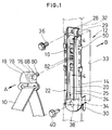
- the collision energy absorbing structure absorbs a collision energy of the vehicle seat belt device 12 capable of adjusting a position for supporting the seat belt 10.
- the seat belt device 12 includes a guide rail 14, a slider 16 and a slip joint 18.
- a guide rail 14 includes a vertically extending slit 20 and a rib 22 extending along the slit 20, the rib 22 becoming a resistance against deformation of the guide rail 14 in the inward direction A of the passenger compartment.
- the guide rail 14 is made by press-molding a steel plate, and the rib 22 consists of a pair of flanges 24, 25.
- the flanges 24, 25 are protruded in the inward direction A of the passenger compartment and has the same vertical length as the slit 20.
- fitting means mentioned later is inserted.
- the pair of flanges may be shaped to protrude in the outward direction B of the passenger compartment, contrary to the embodiment.
- the guide rail 14 is further provided with a fitting hole 28 at its upper portion and a pair of insertions 30 at its lower portion.
- a concave portion 33 is provided in the vehicle body, for example, in a center pillar 32, and in the lower end of the concave portion 33 a hole 34 is opened for inserting each of the pair of insertions 30.
- the guide rail 14 is erected after each insertion 30 is inserted into the hole 34 at an angle, and the circumferential portion of the fitting hole 28 is applied to the center pillar 32. Then, a bolt 36 is passed through the fitting hole 28 to be screwed into a nut (not shown) in the center pillar 32.
- the insertion 30 and the hole 34 are preferably formed to fit each other, thereby to prevent the attached guide rail 14 from getting loose and rattling.
- the connection of the insertion 30 and the hole 34 can make the attachment of the guide rail 14 to the center pillar 32 firm. Instead of providing the insertion 30, however, it is possible to open a fitting hole 38 at the lower end portion of the guide rail 14 in advance and screw into a nut a bolt 40 to be passed through the fitting hole 38.
- both side portions 42, 43 of the circumferential portion 29 of the fitting hole 28 in the guide rail 14 are bent in the same direction as the flanges 24, 25, and furthermore, the rigidity of the circumferential portion 29 is enhanced in a predetermined bending range such that these side portions 42, 43 are overlapped with the flanges 24, 25 over a length L.
- the rigidity is enhanced at the upper portion of the guide rail 14 by the side portions 42, 43, and at the intermediate portion by the flanges 24, 25, and at the lower portion by the pair of insertions 30, so that the guide rail 14 has a great resistance against the deformation in the inward direction A of the passenger compartment.
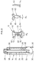
- the slider 16 is, as fully shown in Fig. 2, attached to the guide rail 14 with nails 50 which are deformable under a load over a predetermined one in the outward direction B of the passenger compartment and are disposed in the guide rail 14 outward thereof.
- nails 50 which are deformable under a load over a predetermined one in the outward direction B of the passenger compartment and are disposed in the guide rail 14 outward thereof.
- four nails 50 are provided at the four corners of a rectangular slider body 51.
- the nails 50 are bent in such a manner as to embrace the side portions 54, 55 of the guide rail 14 from the backward.
- the required number of the nails 50 can be determined by the size of a set load and the thickness of the slider 16.
- the slider 16, when mounted on the guide rail 14, can move along the guide rail 14 and can be fixed to the guide rail 14.
- the guide rail 14 has a plurality of lock holes 58 provided along the slit 20 at vertical intervals in the side portions 54, 55.
- the slider 16 has a lock plate 60 supported swingably by the slider 16 and a spring 62.
- the lock plate 60 has a fulcrum portion 64, a pusher portion 65 which can be pushed in the outward direction B of the passenger compartment by an operation of an operation button 68 (Fig. 1) of the slip joint 18, and two lock portions 66 which can be fitted into the lock holes 58 of the guide rail and can be pulled out of the lock holes 58 when the pusher portion 65 is pushed in the outward direction B of the passenger compartment.
- the two lock portions 66 are preferably fitted into the lock holes 58 provided in two rows.
- the illustrated embodiment can stabilize the locked state.
- the spring 62 functions to maintain the lock portions 66 of the lock plate 60 to be fitted into the lock holes 58 of the guide rail 14.
- the slider body 51 has two holes 70, 72.
- the lock plate 60 has a T-shaped configuration as a whole, the width W 1 of the fulcrum portion 64 being greater than the width W 2 of the hole 70 at the lower portion of the slider body 51 and smaller than the vertical length D of the hole 70. Therefore, by inclining the lock plate 60 approximately 90° from the illustrated position with the width of the fulcrum portion 64 positioned vertically, the fulcrum portion 64 is inserted into the hole 70 of the slider body 51, and the lock plate 60 is twisted to be approximately horizontal. Thereby, the fulcrum 64 is hooked on the slider body 51.
- the spring 62 is a leaf spring and has a fulcrum portion 74 with a structure similar to the fulcrum portion 64 of the lock plate 60.
- the slip joint 18 includes, as shown in Fig. 1, an operating button 68 for moving the slider.
- an operating button 68 for moving the slider.
- a cam 76 moves to push out the upper end portion of an L-shaped operating rod 78, which is swingable at the lower end portion as its fulcrum, in the outward direction B of the passenger compartment.
- This operating rod 78 abuts on the pusher portion 65 as shown in Fig. 4(b) and pushes the pusher portion 65 in the outward direction B of the passenger compartment.
- the lock portions 66 of the lock plate are pulled out of the lock holes of the guide rail 14, thereby enabling the slider 16 to move vertically.
- the number of parts can be greatly reduced if moving and fixing of the slider 16 is performed by the lock plate 60 and the spring 62.
- the slip joint 18 is attached to the slider 16 by fitting means 80 and disposed in the guide rail 14 inward of the passenger compartment.
- the fitting means 80 is a bolt. With the bolt 80 screwed into a nut 82 which is fixed at the center of the slider 16, the slip joint 18 is attached to the slider 16 to support a seat belt 10.
- a long bolt 80 is formed so as to be screwed into the nut 82, or the nut 82 is formed so as to be inserted into the slit 20, interposing a cylindrical spacer (not shown) of a suitable size to be inserted into a slit 20, and the nut 82 is axially elongated.
- a space is required between the slider 16 and the bottom surface of the concave portion 33 of the front pillar 32.
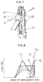
- the rib 96 of the guide rail 94 is projected in the inward direction A of the passenger compartment and consists of a pair of flanges 100, 101 positioned with a slit 98 interposed. These flanges 100, 101 are inclined relative to the inner side surface of the guide rail 94 and are deformable when the slip joint 102 is displaced in the outward direction B of the passenger compartment under a load larger than a predetermined one. Otherwise, the constitution of this embodiment is substantially the same as that of the aforementioned embodiment.
- the energy characteristic D reaches the first peak value C 1 due to the deformation of the flanges 100, 101 and then reaches the second peak value D 2 .
- the second peak value D 2 is of about the same value as the first peak value C 1 but lower than the peak value C 2 at the time of touching the bottom. Also, the entire energy characteristic D approaches the ideal shadowed portion.
Landscapes
- Engineering & Computer Science (AREA)
- Mechanical Engineering (AREA)
- Automotive Seat Belt Assembly (AREA)
Claims (5)
- Aufprallenergieabsorbierende Struktur in einer Fahrzeug-Sicherheitsgurtvorrichtung (12), bei der eine Position nach oben und unten oder vertikal eingestellt kann, um einen Sicherheitsgurt (10) zu halten, mit:einer Führungsschiene (14, 94), die einen sich nach oben und unten oder vertikal erstreckenden Schlitz (20, 98) und eine Rippe (22, 96) aufweist, die sich entlang des Schlitzes (20, 98) erstreckt, so daß einer Verformung der Führungsschiene (14, 94) in die einwärtige Richtung einer Fahrgastzelle ein Widerstand entgegengebracht wird, wobei die Führungsschiene (14, 94) an einem Fahrzeugkörper angebracht ist;einer Gleiteinrichtung (16), die zu der Führungsschiene (14, 94) gehört, sich entlang der Führungsschiene (14, 94) bewegt und an der Führungsschiene (14, 94) feststehend angeordnet werden kann; undeinem Schiebegelenk (18, 102) zum Halten des Sicherheitsgurtes (10), wobei das Schiebegelenk an der Gleiteinrichtung (16) mittels einer Anschlußeinrichtung (80) angebracht ist, die durch den Schlitz (20, 98) der Führungsschiene (14, 94) hindurchgeht und einwärts von der Führungsschiene (14, 94) angeordnet ist;
dadurch gekennzeichnet, daßdie Gleiteinrichtung (16) auswärts von der Führungsschiene (14, 94) angeordnet und an dieser mittels Nägel (50) angebracht ist, die unter einer Last, die von der Fahrgastzelle auswärts gerichtet und größer als ein vorbestimmter Wert ist, verformt werden können. - Aufprallenergieabsorbierende Struktur in einer Fahrgast-Sicherheitsgurtvorrichtung nach Anspruch 1, worin die Rippe (22, 96) der Führungsschiene (14, 94) aus einem Paar von Flanschen (24, 25; 100, 101) besteht, die dadurch hergestellt werden, daß der Schlitz (20, 98) ausgestanzt und das Material dort wie eine Faltflügeltüre erhöht wird, wobei die Flansche (24, 25; 100, 101) derart angeordnet sind, daß der Schlitz zwischen ihnen angeordnet ist.
- Aufprallenergieabsorbierende Struktur in einer Fahrzeug-Sicherheitsgurtvorrichtung nach Anspruch 2, worin die Führungsschiene (14) an ihrem oberen Endabschnitt (28) mit einem Anschlußloch versehen ist und beide Seitenabschnitte (42, 43) der Umfangsabschnitte (29) des Anschlußlochs (28) in die gleiche Richtung wie die Flansche (24, 25) gebogen sind, wobei die Seitenabschnitte (42, 43) über einer bestimmten Länge die Flansche (24, 25) überlappen.
- Aufprallenergieabsorbierende Struktur in einer Fahrzeug-Sicherheitsgurtvorrichtung nach Anspruch 1, worin: die Führungsschiene (14) eine Vielzahl von Arretierlöchern (58) hat, die entlang des Schlitzes (20) vorgesehen sind; das Schiebegelenk (18) einen Betätigungsknopf (68) zum Verschieben der Gleiteinrichtung (16) hat; die Gleiteinrichtung (16) eine Arretierplatte (60) hat, die durch die Gleiteinrichtung (16) schwenkbar gehalten wird, wobei die Arretierplatte (60) einen Schubabschnitt (65), der durch Betätigen des Betätigungsknopfes (68) in die auswärtige Richtung der Fahrgastzelle verschoben werden kann, und Arretierabschnitte (66), die in die Arretierlöcher (58) der Führungsschiene (14) eingefügt und aus den Arretierlöchern (58) herausgezogen werden können, wenn der Schubabschnitt (65) in die auswärtige Richtung der Fahrgastzelle verschoben wird, und eine Feder (62), deren Funktionsweise so ist, daß die Arretierabschnitte (66) der Arretierplatte (60) in den Arretierlöchern (58) der Führungsschiene (14) eingefügt bleiben, aufweist.
- Aufprallenergieabsorbierende Struktur in einer Fahrzeug-Sicherheitsgurtvorrichtung nach Anspruch 1, worin die Rippe (96) der Führungsschiene (94) aus einem Paar von Flanschen (100, 101) besteht, die in die einwärtige Richtung der Fahrgastzelle hervorstehen und derart angeordnet sind, daß der Schlitz (98) zwischen ihnen angeordnet ist, wobei diese Flansche (100, 101) gegen die innere Seitenfläche der Führungsschiene (94) geneigt sind und verformt werden können, wenn das Schiebegelenk (102) unter einer Last, die größer ist als eine vorbestimmte Last, in die auswärtige Richtung der Fahrgastzelle verschoben wird.
Applications Claiming Priority (3)
| Application Number | Priority Date | Filing Date | Title |
|---|---|---|---|
| JP15272295 | 1995-05-29 | ||
| JP7152722A JP2940434B2 (ja) | 1995-05-29 | 1995-05-29 | 車両用シートベルト装置の衝突エネルギ吸収構造 |
| JP152722/95 | 1995-05-29 |
Publications (2)
| Publication Number | Publication Date |
|---|---|
| EP0745520A1 EP0745520A1 (de) | 1996-12-04 |
| EP0745520B1 true EP0745520B1 (de) | 1999-11-17 |
Family
ID=15546729
Family Applications (1)
| Application Number | Title | Priority Date | Filing Date |
|---|---|---|---|
| EP96302817A Expired - Lifetime EP0745520B1 (de) | 1995-05-29 | 1996-04-22 | Aufprallenergieabsorbierende Struktur in einer Fahrzeug-Sicherheitsgurtvorrichtung |
Country Status (4)
| Country | Link |
|---|---|
| US (1) | US5692780A (de) |
| EP (1) | EP0745520B1 (de) |
| JP (1) | JP2940434B2 (de) |
| DE (1) | DE69605148T2 (de) |
Families Citing this family (27)
| Publication number | Priority date | Publication date | Assignee | Title |
|---|---|---|---|---|
| JP3498879B2 (ja) * | 1995-12-27 | 2004-02-23 | 本田技研工業株式会社 | 車両用シートベルト装置 |
| DE19745016C2 (de) * | 1997-10-11 | 2000-07-13 | Porsche Ag | Umlenkbeschlag für Sicherheitsgurte von Fahrzeugen, insbesondere Kraftfahrzeugen |
| GB9809248D0 (en) * | 1998-05-01 | 1998-07-01 | Rover Group | An absorption arrangement |
| DE29912874U1 (de) * | 1999-07-23 | 1999-12-09 | TRW Occupant Restraint Systems GmbH & Co. KG, 73553 Alfdorf | Höhenversteller für Fahrzeugsicherheitsgurt |
| GB2357030B (en) * | 1999-12-09 | 2004-01-07 | Autoliv Dev | Anti-submarining seat |
| US6354628B1 (en) * | 2000-01-13 | 2002-03-12 | Ford-Global Technologies, Inc. | Seat belt anchor assembly |
| DE10011902C1 (de) * | 2000-03-11 | 2001-08-09 | Porsche Ag | Vorrichtung für einen Gurthöhenversteller eines Sicherheitsgurtsystems |
| DE10011906C1 (de) * | 2000-03-11 | 2001-08-09 | Porsche Ag | Vorrichtung für einen Gurthöhenversteller eines Sicherheitsgurtsystems |
| US6749224B1 (en) * | 2002-06-11 | 2004-06-15 | Stojan Stojanovski | Energy absorbing seat belt anchor |
| US6902227B2 (en) * | 2003-03-17 | 2005-06-07 | Autoliv Asp, Inc. | Extrudable energy absorber |
| US7021662B2 (en) * | 2003-07-31 | 2006-04-04 | Daimlerchrysler Corporation | Shoulder belt height adjuster assembly and method |
| US6935701B1 (en) * | 2004-03-05 | 2005-08-30 | Key Safety Systems, Inc. | Articulating lock adjustable turning loop |
| US7198300B2 (en) * | 2004-04-30 | 2007-04-03 | Honda Motor Co., Ltd. | Actuator for an adjustable seat belt D-ring anchor |
| JP3845425B2 (ja) * | 2004-05-12 | 2006-11-15 | 本田技研工業株式会社 | 車両におけるシートベルト装置の調整構造 |
| JP4771211B2 (ja) * | 2005-08-05 | 2011-09-14 | スズキ株式会社 | プリテンショナ機構を備えたシートベルト装置の取付け構造 |
| US7513531B2 (en) * | 2005-10-04 | 2009-04-07 | Takata Seat Belts, Inc. | Simplified height adjuster for D-ring |
| US20070241549A1 (en) * | 2006-04-12 | 2007-10-18 | Key Safety Systems, Inc. | Height Adjuster with Motion Clutch |
| DE102007032547B4 (de) * | 2007-07-12 | 2020-09-10 | Zf Automotive Germany Gmbh | Schlitten für einen Höhenversteller eines Sicherheitsgurtsystems |
| DE202010016105U1 (de) * | 2010-12-01 | 2011-02-17 | Key Plastics Germany Gmbh | Höhenversteller für Fahrzeugsicherheitsgurt |
| KR20140131824A (ko) * | 2013-05-06 | 2014-11-14 | 아우토리브 디벨롭먼트 아베 | 차량용 벨트 백의 디링 조립체 |
| WO2015119014A1 (ja) * | 2014-02-06 | 2015-08-13 | オートリブ ディベロップメント エービー | ハイトアジャスタ装置、ハイトアジャスタ装置を含んだシートベルト装置、およびハイトアジャスタ装置の製造方法 |
| JP2016030536A (ja) * | 2014-07-29 | 2016-03-07 | タカタ株式会社 | シートベルト装置 |
| US9499121B2 (en) | 2014-11-17 | 2016-11-22 | Indiana Mills & Manufacutring, Inc. | Web position adjustment and attenuation apparatus |
| DE202017106964U1 (de) | 2017-11-16 | 2019-02-20 | Sodecia Automotive Europe Gmbh | Führungsschiene für einen Gurthöhenversteller |
| CN108045341A (zh) * | 2017-11-17 | 2018-05-18 | 浙江零跑科技有限公司 | 一种安全带高度调节装置 |
| US11014528B2 (en) * | 2019-04-19 | 2021-05-25 | Toyota Motor Engineering & Manufacturing North America, Inc. | Energy absorption for D-ring attachment bracket |
| US20250049201A1 (en) * | 2023-08-11 | 2025-02-13 | Daniel Wilczek | M.A.S. (Micropals Adapter System) |
Family Cites Families (19)
| Publication number | Priority date | Publication date | Assignee | Title |
|---|---|---|---|---|
| JPS5025690B2 (de) * | 1971-10-23 | 1975-08-26 | ||
| JPS598351U (ja) * | 1982-07-09 | 1984-01-19 | エヌエスケ−・ワ−ナ−株式会社 | アンカ−取付装置 |
| GB8313622D0 (en) * | 1983-05-17 | 1983-06-22 | Britax Wingard Ltd | Anchorage means |
| US4547018A (en) * | 1983-11-30 | 1985-10-15 | Britax (Wingard) Limited | Clamping means for a strap |
| DE3514980A1 (de) * | 1984-05-28 | 1985-11-28 | TRW Repa GmbH, 7071 Alfdorf | Beschlag fuer einen sicherheitsgurt fuer kraftfahrzeuge |
| JPS61196156A (ja) * | 1985-02-27 | 1986-08-30 | Nec Kyushu Ltd | メツキ試験装置 |
| FR2590215B1 (fr) * | 1985-11-19 | 1989-10-13 | Peugeot | Dispositif de renvoi lateral reglable en hauteur pour ceinture de securite de vehicule |
| ES2014005B3 (es) * | 1986-06-05 | 1990-06-16 | Gudrun Schmidt | Herraje desviable muy ajustable para cinturones de seguridad para colocacion en vehiculos |
| JP2661159B2 (ja) * | 1988-07-26 | 1997-10-08 | ブラザー工業株式会社 | 画像記録装置 |
| JP2765011B2 (ja) * | 1989-03-10 | 1998-06-11 | 三菱自動車工業株式会社 | 車体ピラー構造 |
| JPH0413453A (ja) * | 1990-05-08 | 1992-01-17 | Kawasaki Steel Corp | 鋳造用フラックスとそのフラックスを用いたLa含有鋼の鋳造方法 |
| JP2913801B2 (ja) * | 1990-09-05 | 1999-06-28 | タカタ株式会社 | ショルダーアジャスタ |
| JPH04130568A (ja) * | 1990-09-20 | 1992-05-01 | Fujitsu Ltd | 構造活性相関シミュレーション装置 |
| JPH04283149A (ja) * | 1991-03-08 | 1992-10-08 | Takata Kk | ショルダーアジャスタ |
| US5163730A (en) * | 1991-09-03 | 1992-11-17 | General Motors Corporation | Energy absorbing molding attachment bracket |
| DE9113579U1 (de) * | 1991-10-31 | 1992-01-30 | Autoliv GmbH, 2200 Elmshorn | Gurthöhenversteller |
| JPH06239199A (ja) * | 1993-02-17 | 1994-08-30 | Honda Motor Co Ltd | シートベルト用アンカー装置 |
| US5529344A (en) * | 1993-11-30 | 1996-06-25 | Toyota Jidosha Kabushiki Kaisha | Seat belt device for automobile |
| JP2785669B2 (ja) * | 1993-12-21 | 1998-08-13 | トヨタ自動車株式会社 | 自動車用シートベルト装置 |
-
1995
- 1995-05-29 JP JP7152722A patent/JP2940434B2/ja not_active Expired - Fee Related
-
1996
- 1996-04-22 EP EP96302817A patent/EP0745520B1/de not_active Expired - Lifetime
- 1996-04-22 DE DE69605148T patent/DE69605148T2/de not_active Expired - Lifetime
- 1996-05-28 US US08/654,276 patent/US5692780A/en not_active Expired - Lifetime
Also Published As
| Publication number | Publication date |
|---|---|
| EP0745520A1 (de) | 1996-12-04 |
| DE69605148T2 (de) | 2000-05-25 |
| JPH08318818A (ja) | 1996-12-03 |
| US5692780A (en) | 1997-12-02 |
| JP2940434B2 (ja) | 1999-08-25 |
| DE69605148D1 (de) | 1999-12-23 |
Similar Documents
| Publication | Publication Date | Title |
|---|---|---|
| EP0745520B1 (de) | Aufprallenergieabsorbierende Struktur in einer Fahrzeug-Sicherheitsgurtvorrichtung | |
| US4711494A (en) | Foldable headrest for vehicle rear seat | |
| US7731258B2 (en) | Center floor console sliding armrest | |
| US5529344A (en) | Seat belt device for automobile | |
| US7032973B2 (en) | System for locking a first element with a second element, and a seat fitted with such a locking system | |
| US9403458B2 (en) | Headrest moving device | |
| US8146878B2 (en) | Vehicle seat sliding apparatus | |
| US6106012A (en) | Deflection fitting for seat belts of vehicles | |
| US6308589B1 (en) | Locking device for vehicle seats, in particular motor vehicle seats | |
| US7093855B2 (en) | Steering column assembly having clamping mechanism | |
| JPWO2000010430A1 (ja) | ヘッドレストサポート | |
| US11975756B2 (en) | Steering column telescope assembly and energy absorption device | |
| US20030160464A1 (en) | Motor vehicle bumper and motor vehicle | |
| US7393014B2 (en) | Energy absorbing support for a vehicle steering assembly | |
| US20030155788A1 (en) | Mount for securing a part to a support and for positioning it relative to its surroundings, in particular a motor vehicle bodywork part | |
| JP3355343B2 (ja) | シートスライド装置 | |
| EP0832794B1 (de) | Einrichtung zum Befestigen einer Gassack-Abdeckung | |
| US5647628A (en) | Linear one way movement device and passenger seat assembly using the device | |
| US20050082794A1 (en) | Air bag module with adjustable cover | |
| EP1817203B1 (de) | Befestigungsklammer mit zusatzgriff für modularen dachhimmel eines fahrzeugs | |
| JPH05294176A (ja) | 自動車用シートの固定装置 | |
| US5882032A (en) | Attachment device for securing a gas bag module to a vehicle part | |
| US20220266889A1 (en) | Steering column telescope positive lock and breakaway device | |
| JP2006096281A (ja) | 自動車のフードストッパ構造 | |
| CN114401879B (zh) | 用于吸收侧向力的止挡件 |
Legal Events
| Date | Code | Title | Description |
|---|---|---|---|
| PUAI | Public reference made under article 153(3) epc to a published international application that has entered the european phase |
Free format text: ORIGINAL CODE: 0009012 |
|
| 17P | Request for examination filed |
Effective date: 19960429 |
|
| AK | Designated contracting states |
Kind code of ref document: A1 Designated state(s): DE FR GB |
|
| 17Q | First examination report despatched |
Effective date: 19980803 |
|
| GRAG | Despatch of communication of intention to grant |
Free format text: ORIGINAL CODE: EPIDOS AGRA |
|
| GRAG | Despatch of communication of intention to grant |
Free format text: ORIGINAL CODE: EPIDOS AGRA |
|
| GRAH | Despatch of communication of intention to grant a patent |
Free format text: ORIGINAL CODE: EPIDOS IGRA |
|
| GRAH | Despatch of communication of intention to grant a patent |
Free format text: ORIGINAL CODE: EPIDOS IGRA |
|
| GRAA | (expected) grant |
Free format text: ORIGINAL CODE: 0009210 |
|
| AK | Designated contracting states |
Kind code of ref document: B1 Designated state(s): DE FR GB |
|
| ET | Fr: translation filed | ||
| REF | Corresponds to: |
Ref document number: 69605148 Country of ref document: DE Date of ref document: 19991223 |
|
| PLBE | No opposition filed within time limit |
Free format text: ORIGINAL CODE: 0009261 |
|
| STAA | Information on the status of an ep patent application or granted ep patent |
Free format text: STATUS: NO OPPOSITION FILED WITHIN TIME LIMIT |
|
| 26N | No opposition filed | ||
| REG | Reference to a national code |
Ref country code: GB Ref legal event code: IF02 |
|
| REG | Reference to a national code |
Ref country code: GB Ref legal event code: 746 Effective date: 20041018 |
|
| REG | Reference to a national code |
Ref country code: FR Ref legal event code: D6 |
|
| PGFP | Annual fee paid to national office [announced via postgrant information from national office to epo] |
Ref country code: DE Payment date: 20120425 Year of fee payment: 17 |
|
| PGFP | Annual fee paid to national office [announced via postgrant information from national office to epo] |
Ref country code: FR Payment date: 20120504 Year of fee payment: 17 Ref country code: GB Payment date: 20120418 Year of fee payment: 17 |
|
| GBPC | Gb: european patent ceased through non-payment of renewal fee |
Effective date: 20130422 |
|
| PG25 | Lapsed in a contracting state [announced via postgrant information from national office to epo] |
Ref country code: GB Free format text: LAPSE BECAUSE OF NON-PAYMENT OF DUE FEES Effective date: 20130422 Ref country code: DE Free format text: LAPSE BECAUSE OF NON-PAYMENT OF DUE FEES Effective date: 20131101 |
|
| REG | Reference to a national code |
Ref country code: FR Ref legal event code: ST Effective date: 20131231 |
|
| REG | Reference to a national code |
Ref country code: DE Ref legal event code: R119 Ref document number: 69605148 Country of ref document: DE Effective date: 20131101 |
|
| PG25 | Lapsed in a contracting state [announced via postgrant information from national office to epo] |
Ref country code: FR Free format text: LAPSE BECAUSE OF NON-PAYMENT OF DUE FEES Effective date: 20130430 |