EP0745461B1 - Rasoir à sec - Google Patents
Rasoir à sec Download PDFInfo
- Publication number
- EP0745461B1 EP0745461B1 EP96112945A EP96112945A EP0745461B1 EP 0745461 B1 EP0745461 B1 EP 0745461B1 EP 96112945 A EP96112945 A EP 96112945A EP 96112945 A EP96112945 A EP 96112945A EP 0745461 B1 EP0745461 B1 EP 0745461B1
- Authority
- EP
- European Patent Office
- Prior art keywords
- shaving
- cutter
- unit
- outer cutter
- units
- Prior art date
- Legal status (The legal status is an assumption and is not a legal conclusion. Google has not performed a legal analysis and makes no representation as to the accuracy of the status listed.)
- Expired - Lifetime
Links
- 230000008878 coupling Effects 0.000 claims description 17
- 238000010168 coupling process Methods 0.000 claims description 17
- 238000005859 coupling reaction Methods 0.000 claims description 17
- 230000000694 effects Effects 0.000 abstract description 2
- 210000004209 hair Anatomy 0.000 description 52
- 239000011888 foil Substances 0.000 description 23
- 238000010276 construction Methods 0.000 description 13
- 238000005520 cutting process Methods 0.000 description 10
- 230000007246 mechanism Effects 0.000 description 9
- 238000000034 method Methods 0.000 description 5
- 239000002184 metal Substances 0.000 description 3
- 230000003534 oscillatory effect Effects 0.000 description 3
- 230000008569 process Effects 0.000 description 3
- 229910000831 Steel Inorganic materials 0.000 description 2
- 230000009471 action Effects 0.000 description 2
- 230000000712 assembly Effects 0.000 description 2
- 238000000429 assembly Methods 0.000 description 2
- 230000008901 benefit Effects 0.000 description 2
- 238000010438 heat treatment Methods 0.000 description 2
- 238000004519 manufacturing process Methods 0.000 description 2
- 229920003023 plastic Polymers 0.000 description 2
- 239000004033 plastic Substances 0.000 description 2
- 230000004044 response Effects 0.000 description 2
- 230000000284 resting effect Effects 0.000 description 2
- 230000000717 retained effect Effects 0.000 description 2
- 239000010959 steel Substances 0.000 description 2
- 238000009966 trimming Methods 0.000 description 2
- 230000002411 adverse Effects 0.000 description 1
- 230000006835 compression Effects 0.000 description 1
- 238000007906 compression Methods 0.000 description 1
- 238000010586 diagram Methods 0.000 description 1
- 238000006073 displacement reaction Methods 0.000 description 1
- 239000000428 dust Substances 0.000 description 1
- 239000000463 material Substances 0.000 description 1
- 230000004048 modification Effects 0.000 description 1
- 238000012986 modification Methods 0.000 description 1
- 238000003825 pressing Methods 0.000 description 1
- 239000011435 rock Substances 0.000 description 1
- 230000036346 tooth eruption Effects 0.000 description 1
Images


Classifications
-
- B—PERFORMING OPERATIONS; TRANSPORTING
- B26—HAND CUTTING TOOLS; CUTTING; SEVERING
- B26B—HAND-HELD CUTTING TOOLS NOT OTHERWISE PROVIDED FOR
- B26B19/00—Clippers or shavers operating with a plurality of cutting edges, e.g. hair clippers, dry shavers
- B26B19/02—Clippers or shavers operating with a plurality of cutting edges, e.g. hair clippers, dry shavers of the reciprocating-cutter type
- B26B19/04—Cutting heads therefor; Cutters therefor; Securing equipment thereof
- B26B19/048—Complete cutting head being movable
-
- B—PERFORMING OPERATIONS; TRANSPORTING
- B26—HAND CUTTING TOOLS; CUTTING; SEVERING
- B26B—HAND-HELD CUTTING TOOLS NOT OTHERWISE PROVIDED FOR
- B26B19/00—Clippers or shavers operating with a plurality of cutting edges, e.g. hair clippers, dry shavers
- B26B19/02—Clippers or shavers operating with a plurality of cutting edges, e.g. hair clippers, dry shavers of the reciprocating-cutter type
- B26B19/04—Cutting heads therefor; Cutters therefor; Securing equipment thereof
- B26B19/044—Manufacture and assembly of cutter blocks
-
- B—PERFORMING OPERATIONS; TRANSPORTING
- B26—HAND CUTTING TOOLS; CUTTING; SEVERING
- B26B—HAND-HELD CUTTING TOOLS NOT OTHERWISE PROVIDED FOR
- B26B19/00—Clippers or shavers operating with a plurality of cutting edges, e.g. hair clippers, dry shavers
- B26B19/02—Clippers or shavers operating with a plurality of cutting edges, e.g. hair clippers, dry shavers of the reciprocating-cutter type
- B26B19/04—Cutting heads therefor; Cutters therefor; Securing equipment thereof
- B26B19/10—Cutting heads therefor; Cutters therefor; Securing equipment thereof involving two or more different types of reciprocating cutting elements, e.g. a pair of toothed shearing elements combined with a pair of perforated cutting elements or a combined toothed and perforated cutting assembly
Definitions
- the present invention relates to dry-shaving apparatus comprising at least two parallel shaving units for close shaving each consisting of a respective outer cutter, an inner cutter and at least one bias spring, and a further shaving unit for rough shaving, as per the preamble of claim 1 and disclosed in e.g. US-A-3 589 005.
- each outer cutter is secured on a shaving head frame arranged on the housing.
- the inner cutters are mounted on a common coupling element which is connected to a drive element of an electrical drive.
- Each inner cutter is pressed against the associated outer cutter by means of a respective spring element which ensures good engagement of the inner cutter with the outer cutter.
- the outer cutter is mounted on a removable frame coupled to the shaving head frame, which is pivotably mounted on the housing of the dry-shaving apparatus.
- a dry-shaving apparatus having four parallel shaving units is known from US-A-3 589 005.
- the two outer shaving units constructed as short hair cutters, each consist of an outer cutter, an inner cutter and a spring element arranged between a drive element and the inner cutter.
- Between the two outer shaving units are provided two comb-like long hair cutters, each of which consists of a toothed cutting comb and an associated toothed cutting blade, particularly for trimming.
- these toothed long hair trimmers are mounted for adjustment, both together and also independently of one another, relative to the short hair cutters.
- An object of the present invention is to provide a dry-shaving apparatus of the type initially defined in which engagement of the shaving units with the skin to be shaved is improved in a simple manner, whilst permitting combination shaving, i.e. simultaneous cutting of long and short hairs.
- dry-shaving apparatus comprising a pair of first shaving units of a first type for close shaving and a second shaving unit of a second type for rough shaving, each of said first shaving units including an outer cutter formed from a curved thin plate provided with a plurality of cutter apertures and an inner cutter reciprocatingly slidable along the inner surface of said outer cutter and a bias spring biasing the inner cutter against the outer cutter, wherein the pair of first shaving units for close shaving are held by a shaving head frame substantially parallel with and in juxtaposition to each other and between which said second shaving unit for rough shaving is disposed, characterized in that said second shaving unit for rough shaving and two first shaving units for close shaving are supported by said shaving head frame, said second shaving unit is movably supported by said frame and is upwardly biased by the biasing force of a resilient member and the biasing force of said second shaving unit for rough shaving is set to permit floating movement of the second shaving unit relative to each first shaving unit under forces applied during shaving.
- said second shaving unit for rough shaving includes an outer cutter comprising a top wall and two side walls and having a U-shaped cross-section, and an inner cutter disposed within said outer cutter and reciprocatingly slidable along the inner surface of the top wall of said outer cutter, said top wall of said outer cutter is provided with slits, and said slits also open on said side walls.
- the width of said top wall of said outer cutter of said second shaving unit for rough shaving is equal to the width of the lower portion of said outer cutter.
- said cutter unit for rough shaving comprises an assembly including an outer cutter, an inner cutter in sliding contact with the inner surface of said outer cutter, and a push-up spring disposed between a plate fixed to said outer cutter and said inner cutter for urging said inner cutter toward said outer cutter, and is attached to said shaving head frame through an attachment member and wherein a stop is provided between said cutter unit for rough shaving and said shaving head frame for controlling the upper movement thereof, so that a resilient member which is subject to positional control by said stop can be urged upward so as to deform and provide a pre-loaded floating biasing force relative to said assembly.
- Fig. 1 shows the upper part of a dry-shaver having a housing 1, an on-off switch 2, a beard trimmer 3 having cutting teeth, an upper housing surface 4, a drive pin 6 protruding from an opening 5 in the upper housing surface 4, support arms 9 and 10 extending from respective narrow housing sides 7 and 8, and a shaving head RK mounted for rocking about an axis X-X by means of bearing pins 11 receivable in bearing holes 12 in the carrier arms 9 and 10.
- the shaver head RK three mutually parallel shaving units 13, 14 and 15 are provided, of which the two outer shaving units 13 and 14 are constructed as short hair cutters and the intermediate shaving unit 15 is constructed as a long hair cutter.
- the outer cutters 16 and 17 of the short hair cutter units 13, 14 are secured on a frame 19 which is removable from the shaving head from 18.
- the outer cutter 20 of the shaving unit 15 is mounted for movement relative to the outer cutters 16 and 17 in the removable frame 19.
- Fig. 2 shows a cross-section through the upper part of housing 1 and the rockable shaving head RK.
- Two inner cutters 21 and 22 of the short hair shaving units 13 and 14 contact respective outer cutters 16 and 17 mounted in arched form in the frame 19, the outer cutters 16 and 17 preferably being constructed as shaving foils.
- the coupling element 23 consists of a base plate 24 with three integrally formed cup-shaped receptacles 25, 26 and 27 and cooperating cup-shaped covers 28, 29 and 30 as well as respective guide pins 42, 43 and 44 provided inside respective receptacles 25, 26, 27 and associated covers 28, 29 and 30, and including compression springs 31, 32, 33 surrounding respective pins.
- the coupling element 23 is coupled by means of the guide pin 44 with a drive element 40, consisting of an oscillating bridge - see Fig. 3. Facing the housing, the drive element 40 has a slot 41, in which engages the drive pin 6 to accommodate an oscillating movement and also a rocking movement of the head RK.
- the shaving unit 15 constructed as a long hair cutter and, consisting of the outer cutter 20, the inner cutter 34, a spring 45 and a coupling element 46, and is operatively coupled to the receptacle cover 30 and thus to the coupling element 23. Further details of the construction and arrangement of the shaving unit 15 are illustrated in Fig. 3 and will be described in more detail in the following, retaining the previously employed reference signs.
- the cutter On the respective ends of the outer cutter 20, the cutter is provided with guide elements 47, 48, and is movably mounted via these in guide grooves 51, 52 formed in the inner walls 49, 50 of the removable frame 19.
- On the guide elements 47, 48 are provided bearing arms 53, 54 extending towards the coupling element 46 as a counter-bearing for a spring 45, lying on the coupling element 46.
- the coupling element 46 and the spring 45 as well as the inner cutter 34 are rigidly connected together. As a consequence, the inner cutter 34 is pressed, by means of the spring 45 engaging with the bearing arms 53, 54, against the outer cutter 20.
- the spring 33 arranged in the coupling element 23 serves to accommodate the relative motion of the shaving unit 15 constructed as a long hair cutter, relative to the shaving units 13 and 14 constructed as short hair cutters - see Fig. 2 - in response to a force externally applied to the shaving units.
- the spring 33 arranged in the coupling element 23 serves to accommodate the relative motion of the shaving unit 15 constructed as a long hair cutter, relative to the shaving units 13 and 14 constructed as short hair cutters - see Fig. 2 - in response to a force externally applied to the shaving units.
- the spring 33 provided for permitting the relative motion of the shaving unit 15 can according to a further embodiment - not illustrated - be arranged to engage at both ends of the shaving head 15 between on the one hand a wall of the shaving head frame 18 and on the other hand the guide elements 47, 48.
- Fig. 4 shows a further embodiment of a dry shaver having a long hair cutter 15 movable relative to the short hair cutter shaving units 13, 14.
- a shaving head frame 60 which is removably connected to the housing 1.
- the drive pin 6 transmitting oscillatory motion is coupled via a guide pin 44 directly with the coupling element 23.
- the arrangement and construction of the inner cutters 21, 22 as well as the shaving unit 15 constructed as a long hair cutter on the coupling element 23 corresponds to the embodiment according to Figs. 2 and 3.
- the outer cutters 16 and 17 of the shaving units 13, 14 are secured on the shaving head frame 60.
- the short hair cutter shaving unit 15 corresponds in its construction to the embodiments illustrated in Fig. 3 and is coupled via the coupling element 46 to the spring assembly 30. Deviating from the embodiment according to Fig. 3, the respective ends of the shaving unit 15 are movably mounted by means of the guide elements 47, 48 in guide grooves - not illustrated - formed in the inner walls 49 of the shaving head frame 60.
- a shaver head RK not part of the claimed invention includes a first shaving unit 13 and a second shaving unit 14. Each of these units is supported at each end by a depending link, (part of the frame) and each of these four links is carried on an upper transverse rocker link 131 and a lower such link 141. In Fig. 5 the upper link 131 and lower link 141 are visible at one end of the head RK.
- Each of the rocker links is connected to respective shaving units 13 and 14 by a respective pair of living hinges 150, 151 or 152, 153.
- the housing body of the shaver provides pivot members 160, 161 on which the rocker links 131, 141 are pivotably mounted. This assembly allows the shaving units to move up and down in response to externally applied force.
- Each shaving unit of Figs. 5 and 6 which are not part of the claimed invention comprises an inner cutter, an outer cutter (preferably a foil) and at least one spring element.
- Figs. 7, 8, 9a, and 9b show how each inner cutter 21, 22 is mounted and driven.
- the inner cutter 21 is pressed against the inside of an arched shaving foil 16.
- the foil 16 is in fact carried on a structural element which includes a first end plate 210 and a second end plate 220 at opposite ends of the foil 16.
- the shaver head is completed by a common housing or shell which supports the pivotal movement of the four rocker links 131, 141 and also serves to attach the shaver head to the shaver body.
- the cutter 21 is urged into contact with the surrounding foil by first and second spring biasing elements 230, 240.
- Each of these elements has a hollow cup base 250 and slightly larger domed cap 260 which is able to move telescopically up and down on the cup 250 guided by a pin 271.
- a helical spring 270 in the hollow interior of the element 230 urges the cup 250 and cap 260 apart.
- a detent 280 around the respective lips of the cup 230 and cap 260 prevents these two components from separating, whilst an eye 290 on the top of the cap 260 receives a pin 300 by which the biasing element 230 is connected at its upper end to the cutter 21.
- each biasing element 230, 240 are provided two laterally projecting trunnion pins 311, 312 which rest on respective corresponding support surfaces 91, 92 cantilevered out from the adjacent frame.
- the cutter 21 has a multiplicity of parallel metal cutting blades 400. All of these blades extend outwardly from a backing portion 410 of the cutter.
- a slot 420 extends transversely to the length of the cutter 21 in a drive-receiving element 430 which is fastened to the backing portion 410 by a pair of rivets 440.
- a drive pin 6 which extends upwardly from the top of the shaver body (not shown) has an upper end 460 which is received within the slot 420, in order to impart oscillatory motion to cutter 21.
- each of the two biasing devices 230, 240 rocks on its pivot pin 300 and support surface 90, 91, with the spring 270 urging the cap 260 and cutter 21 upwardly, but even when the cutter is at the furthest extent of its lateral movement with the biasing devices 230, 240 fully inclined to the vertical at their maximum angle, as shown in Fig. 8, the detent surfaces 280 remain out of contact, so that the biasing force provided by the spring 270 is still effective.
- the pin and transverse slot arrangement allows the cutter 21 to move transversely, as has been described above with reference to Figs. 5 and 6, whether or not the drive pin 6 also moves sideways. In fact, there is no need for the drive pin 6 to have any capacity at all for sideways movement. Moreover, the pin 6 engages with slot 420 over sufficient length to prevent disengagement during the rocking movement of the shaving units described with reference to Figs. 5 and 6, which are not part of the claimed invention.
- cap and cup telescopic arrangement for the biasing elements 230, 240 is that their operation is less likely to be adversely affected by debris if the cap and cup are effective to prevent debris from fouling the turns of the spring 270 which provides the biasing force.
- each shaver unit 13, 14 can be made.
- the cutter 21 itself is open over its base area, as is described in more detail hereinafter, particularly with reference to Fig. 31.
- the drive pin 6 has an upper end 460 which is bifurcated, to provide a first drive peg 500 which is received within a slot 420 of the shaving unit 13 and a second drive peg 520 which is received within a corresponding slot of the shaving unit 14.
- the unit 14 is at its limit of upward movement, and so of course unit 13 is at the limit of its downward movement.
- the peg 500 is at the top of the slot 420 and the peg 520 is near the lower open end of its slot.
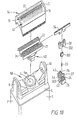
- Fig. 10 is an exploded view of a dry-shaving apparatus, not forming part of the invention, having three shaving units, including two short hair cutters 13 and 14 and a long hair cutter 15 positioned between the short hair cutters.
- the long hair cutter 15 is mounted for movement relative to short hair cutters 13 and 14 under forces applied during shaving.
- the outer cutter of the long hair cutter is in the form of a shaving foil 20 with transverse slots.
- the under cutter 34 takes the form of a comb-like bar which oscillates longitudinally beneath the foil 20.
- the undercutters 21 and 22 for the short hair cutters take the form of arcuate slotted members of the form generally as shown in Fig. 31.
- All three undercutters 21, 22 and 34 are mounted on a sub-assembly 40 acting as a drive element for the undercutters, i.e. acting to transmit the drive from the base of the rockable shaving head RK to the undercutters.
- the sub-assembly 40 consists of an upper cover member 30, which is rivetted to the central undercutter 34, a coupling element or fulcrum 301 on which the undercutter 34 pivots when assembled, a pressure spring 33 for biasing the undercutter against the outer foil 20 and a base plate 24 providing three cup-like receptacles 25, 26 and 27 carrying respective drive pins 42, 43 and 44.
- Coupling element 301 is slidably engaged with drive pin 44 and biased by the spring 33.
- Further springs 31 and 32 are provided in receptacles 25 and 26, as best shown in Fig. 11.
- Cover member 30 has two lateral apertures 302 which engage loosely over lateral lugs 303 on receptacle 27.
- pin 44 protrudes from the sub-assembly 40 and engages in and is retained by a hole 5 in the base surface of the rockable shaving head RK.
- the hole 5 is surrounded by an annular elastomeric seal member 5a to prevent the ingress of dust or shaving debris.
- Fig. 11 is a transverse exploded sectional view through the shaving head, it may be seen how the outer cup-like receptacles 25 and 26 are enclosed by respective covers 28 and 29, which also provide slide bores for receiving the drive pins 42 and 43.
- Fig. 12 shows the components of Fig. 11 in an assembled condition.
- the Figure also shows an enlarged view of the form of outer cutter for the central long hair cutter 15.
- Fig. 13 is a view similar to that of Fig. 12 but with an alternative form of inner cutter for the central long hair cutter.
- the inner cutter has a U-shaped cross-section and is similar to the undercutter described hereinafter with reference to Figs. 16, 17 and 18.
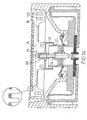
- Fig. 14 shows a longitudinal vertical section through the central long hair cutter 15 of Fig. 12.
- the Figure shows particularly the way in which the undercutter 34 to which the cap member 30 is riveted, rests on the coupling member 301 in a manner to permit rocking movement about a longitudinal or transverse axis.
- Fig. 14 also shows how the outer cutter 20 is mounted for vertical movement by means of a pin and slot arrangement 120 at each end to enable vertical floating motion of the central long hair cutter against the bias of the spring 33.
- the characteristics of spring 33 are set relative to those of springs 31 and 32 such that the vertical floating motion of the long hair cutter 15 will occur in use under the influence of normal shaving forces applied as the shaver glides over the skin.
- Fig. 15 is a longitudinal vertical section through the short hair cutter 16 of Fig. 12.
- the undercutter 21 is pivotally secured to the cover member 28 which is interengaged with the cup member 25 forming a part of the base plate 24.
- the pin 42 is mounted in a bore in the member 25 and is able to slide in a slide bore in the cover member 28, which can move against the bias of spring 31.
- the spring 31 thus functions to push the undercutter 21 into shaving contact with the outer foil 16.
- Fig. 16 shows an isometric exploded view of a further dry shaver apparatus not part of the claimed invention, in which a central long-hair cutter 15 is mounted for floating movement relative to two short hair cutters 13 and 14.
- the individual undercutters 21, 22 and 34 are individually mounted on respective spring assemblies and are separately driven by respective drive pins 6a, 6b and 6c.
- Drive pins 6b and 6c are integral parts of a drive member 66 through which the central drive pin 6a is inserted.
- the whole undercutter assembly is held together and retained in the outer cutter frame by a generally rectangular wire spring 90.
- Fig. 16 also shows the individual components supporting the undercutter 34 for the long hair trimmer 15. These components include a flat spring 341 and two inclined guide members 342 and 343 which are riveted to the undercutter 34. The characteristics of the flat spring 341 are adjusted to permit the floating movement during shaving.
- Fig. 17 shows the internal structure of the spring assemblies 40a and 40b in more detail. Fig. 17 also shows more clearly how the individual components are assembled together and held via the wire spring 90. The assembled position is shown in Fig. 18.
- Fig. 19 is a view similar to that of Fig. 18, showing an alternative construction of undercutter for the central long hair trimmer 15.
- the undercutter corresponds to the form of undercutter described and illustrated in the embodiment of Fig. 10.
- Fig. 20 is a vertical sectional view through one of the short hair cutters of Fig. 18.
- Fig. 20 shows particularly clearly the construction of the spring assembly 40a, comprising a cover member 28a, a base member 25a and two internal springs 31a and 31b for providing a biasing force, biasing the undercutter 21 into shaving contact with the outer cutter 16.
- Fig. 21 is a vertical sectional view through the long hair cutter 15 of Fig. 18.
- the Figure also shows how the drive pin 6a engages between the two guide members 342 and 343 and pushes against the flat spring 341. This provides the necessary biasing force pushing the undercutter 34 into shaving contact with the outer cutter 20.
- Fig. 22 shows a vertical sectional view through the long hair cutter 15 of the apparatus of Fig. 19.
- the inner cutter 34 is in the form of a comb-like bar similar to the form of undercutter shown in Fig. 10.
- the drive pin 6a engages between two guide members 342 and 343 riveted to the undercutter 34.
- the biasing force is provided not by a flat spring, but rather by a spring wire 341a, which has its properties selected to permit the required floating movement during shaving.
- Fig. 23 shows a shaver not part of the claimed invention having fixed geometry in which the shaving head RK rotates on the shaver body 50 through a conventional pivot (not shown) or using living hinges.
- fixed geometry is meant that the individual shaving units 13, 14 are intercoupled by being fixed relative to one another in the head RK. The head thus tilts as a whole.
- Lower curved surfaces 61 are shaped to clear counter surfaces 62 of the shaver body.
- the first shaving unit 13 in the head RK has a shaving foil 16 in the form of a relatively shallow arch, and inside this arch is an inner cutter 21.
- Surfaces of the head RK support the long edges of the foil arch 16 and the lower ends of spring biasing means (not shown) which urge the inner cutter 21 up onto the inside of the arch of the foil 16.
- the second shaving unit 14 in the head RK is identical to the first, and has a foil 17 and inner cutter 22. Between the first and second shaving units, and lying parallel to them is a long hair cutting unit 15 which also has a foil 20 and inner cutter 34, but the foil 20 has slots instead of small apertures, for improved catching of long hairs, for cutting by the inner cutter 34. As in other embodiments of the invention, the long hair cutter 15 is mounted for floating movement, against a spring, relative to short hair cutters 13 and 14.
- a transverse drive slot 62 is provided in a drive yoke 63 mounted mid-way along the length of the cutter 21, and a drive peg 64, upstanding from the body, engages with the slot 62.
- the flank pieces of the slot 62 are large enough always to flank the drive peg 64 irrespective of the rotational position of the head RK on the shaver body 7.
- the extreme positions of the drive peg 64 in the slot 62 can be seen in Fig. 23.
- the second cutter 22 is driven by a second drive peg 65 in just the same way.
- the inner cutter 34 of the trimmer unit 15 is driven in a corresponding manner.
- Figure 24 shows a perspective view of the working end of dry shaving apparatus not part of the claimed invention incorporating a rockable head RK having three shaving units 13, 14 and 15.
- a trimmer 3 is provided on the front surface of the body 1.
- Figure 24 shows the rockable head RK in its central position.
- Figure 25 corresponds to Figure 24 but shows the rockable head RK in a fully tilted position.
- Fig. 26, comprising individual Figures 26(a), 26(b) and 26(c), may be regarded as a modification of the arrangement of Fig. 23 in the sense that in both Fig. 23 and in Fig. 26 the shaver head is of "fixed geometry" (although movable relative to the shaver body), in that the individual shaving units are fixed in position relative to the shaver head. Whilst in the arrangement of Fig. 23, the pivoting or rocking movement of the shaver head is achieved by means of a conventional pivot or living hinge, in the arrangement of Fig. 26 a parallelogram linkage is employed. In Fig. 26 the shaver head RK is mounted on upper ends of two pairs of vertical side members 71 and 72.
- One pair of side members may be provided at each side of the shaver.
- the pair of vertical side members 71 and 72 constitute, in combination with transverse link members 73 and 74, a four bar mounting linkage.
- Each of links 73 and 74 constitutes a bell crank lever.
- the bell crank levers 73 and 74 are pivoted at respective pivot points 77 and 78 to fixed points of the shaver frame (not shown). These fixed points of the shaver frame are located on a central plane 75 of the shaver.
- a virtual pivot centre 76 is produced well above the points of attachment of the vertical side members 71 and 72 to the shaver head RK.
- the virtual pivot may be located on, above or below skin level in dependence upon the size of the pivoting triangles or bell crank links 73 and 74. This may be achieved without the need for a physical upper pivot location which is required in the arrangement of Fig. 23.
- Fig. 26(a) shows the linkage pivoted towards the right-hand side
- Fig. 26(b) shows the linkage in a central position
- Fig. 26(c) shows the linkage pivoted to the left.
- this method of mounting the shaver head provides a single solidly linked foil frame assembly which is capable of supporting a multiplicity of foils, for example three foils as shown in Fig. 23, 24 or 25 or more.
- the tendency of the individual foils to pivot during shaving, leading to shaving on the side of the foil can be eliminated.
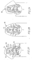
- FIG. 27 to 29 an alternative form of parallelogram linkage not forming part of the claimed invention is illustrated comprising vertical side member 71 and 72, and two rocking links 73 and 74, in the form of bell crank levers, pivoted on the body at pivot point 77 and 78. Contrary to the method employed in Fig. 26, here the upper ends of the arms 71 and 72 are secured to a link member 79 which in turn is secured to the side of the rocking head RK. Moreover, all pivot points of the mechanism are achieved by means of living hinges 150 to 155 in a similar manner to that illustrated in Figs. 5 and 6. Clearly Fig. 27 and 29 show the mechanism in the two extremes of the tilting action, whereas Fig. 23 shows the mechanism in its central position.
- Fig. 30 shows the apparatus of Figs 27 - 29 in a front elevation.
- the form of the pivot points 77 and 78 is shown more clearly in this Figure.
- the Figure also demonstrates that corresponding pivot points 77a and 78a are provided on the other side of the apparatus, together with a corresponding tilting mechanism.
- Fig. 28 may be regarded as an end view of the apparatus of Fig. 30.
- an inner cutter 21 has a multiplicity of arcuate bridge cutter elements 400, which define a part cylindrical cutting surface for cooperation with a cutting foil of the shaver on the outwardly convex outer surface of the bridge elements.
- the arc of the bridge elements is part-circular, so that the cutter is entirely open from below, to provide a high degree of debris transparency.
- All the first ends 82 of the bridge elements 400 are linked together by a first support beam 410 which extends the length of the cutter.
- a similar support beam 84 links together all the second ends of the bridge elements 400, so that the first and second beams face each other from opposite sides of the bridge of the cutter.
- each of the beams 410, 84 is mounted a yoke 430 of plastics material, mounted by means of two small plastics rivets 440 which extend through bores in the yoke 430 and through fins 86 which extend for a short distance downwardly from the remainder of the beam 410.
- Each yoke 430 defines a slot 420 for accommodating the transverse pin of a drive peg.
- the first step is to press a flat work piece of hardenable steel into the required arcuate shape, and then to form the cutter elements by transverse slitting, by grinding or cutting.
- the requisite heat treatment process is performed before or after the slitting process, but preferably before.
Landscapes
- Engineering & Computer Science (AREA)
- Forests & Forestry (AREA)
- Mechanical Engineering (AREA)
- Life Sciences & Earth Sciences (AREA)
- Manufacturing & Machinery (AREA)
- Dry Shavers And Clippers (AREA)
- Reverberation, Karaoke And Other Acoustics (AREA)
- Finish Polishing, Edge Sharpening, And Grinding By Specific Grinding Devices (AREA)
- Drying Of Solid Materials (AREA)
- Surface Acoustic Wave Elements And Circuit Networks Thereof (AREA)
- Mechanical Treatment Of Semiconductor (AREA)
- Control And Other Processes For Unpacking Of Materials (AREA)
- Auxiliary Devices For Music (AREA)
- Glass Compositions (AREA)
Claims (11)
- Appareil de rasage à sec comprenant une paire de premières unités de rasage (13, 14) d'un premier type pour le rasage de près, et une deuxième unité de rasage (15) d'un deuxième type pour le rasage grossier, chacune desdites unités de rasage (13, 14) comprenant un couteau extérieur (16, 17) formé d'une plaque mince centrée pourvue d'une pluralité d'ouvertures de coupe, et un couteau intérieur (21, 22) susceptible de coulisser en va-et-vient le long de la surface intérieure dudit couteau extérieur (16, 17) et un ressort qui repousse le couteau intérieur contre le couteau extérieur, dans lequel la paire de premières unités de rasage (13, 14) pour le rasage de près sont maintenues par un cadre de tête de rasage (18) sensiblement parallèles et juxtaposées l'une à l'autre, ladite deuxième unité de rasage (15) pour le rasage grossier étant disposée entre lesdites premières unités de rasage,
caractérisé en ce que :
ladite deuxième unité de rasage (15) pour le rasage grossier et deux premières unités de rasage (13, 14) pour le rasage de près sont supportées par ledit cadre de tête de rasage (18), ladite deuxième unité de rasage (15) étant supportée de façon mobile par ledit cadre (18) et étant repoussée vers le haut par la force de sollicitation d'un élément élastique, et la force de sollicitation de ladite deuxième unité de rasage (15) pour le rasage grossier étant fixée de façon à permettre un mouvement de flottement de la deuxième unité de rasage par rapport à chacune des premières unités de rasage sous les forces appliquées pendant le rasage. - Appareil de rasage à sec selon la revendication 1, dans lequel ladite deuxième unité de rasage (15) pour le rasage grossier inclut un couteau extérieur (20) comprenant une paroi supérieure et deux parois latérales, et présentant une section transversale en forme de U, et un couteau intérieur (34) disposé à l'intérieur dudit couteau extérieur (20) et capable de coulisser en va-et-vient le long de la surface intérieure de la paroi supérieure dudit couteau extérieur (20), ladite paroi supérieure dudit couteau extérieur (20) étant pourvue de fentes, et lesdites fentes étant également ouvertes sur lesdites parois latérales.
- Appareil de rasage à sec selon la revendication 2, dans lequel la largeur de ladite paroi supérieure dudit couteau extérieur (20) de ladite deuxième unité de rasage (15) pour le rasage grossier est égale à la largeur de la partie inférieure dudit couteau extérieur (20).
- Appareil de rasage à sec selon la revendication 1, dans lequel ladite unité de coupe (15) pour le rasage grossier comprend un ensemble qui inclut un couteau extérieur (20), un couteau intérieur (34) en contact coulissant avec la surface intérieure dudit couteau extérieur (20), et un ressort de poussée (45) disposé entre ledit couteau intérieur (34) et des bras porteurs (53, 54) fixés audit couteau extérieur (20) pour repousser ledit couteau intérieur (34) en direction du couteau extérieur (20), et attaché audit cadre de tête de rasage (18) par un engagement mobile d'éléments d'attache (47, 48) avec des parois intérieures d'un cadre amovible (19) susceptible d'être monté sur ledit cadre de tête de rasage (18) de sorte qu'un élément élastique (33) peut repousser ladite deuxième unité de rasage (15) vers le haut pour assurer une force de sollicitation en flottement prédéterminé par rapport audit ensemble.
- Appareil de rasage à sec selon la revendication 4, dans lequel ledit cadre amovible (19) est porté sur ledit cadre de tête de rasage (18) pour tenir lesdits couteaux extérieurs (16, 17), et dans lequel ledit cadre amovible (19) possède deux côtés longitudinaux, chacun pourvu d'une partie découpée.
- Appareil selon l'une quelconque des revendications 2 à 5, dans lequel ladite deuxième unité de rasage (15) est pourvue d'un premier élément de sollicitation (33) pour permettre ledit mouvement, et d'un élément de sollicitation additionnel (45) pour maintenir l'engagement entre les couteaux intérieur et extérieur de ladite unité.
- Appareil selon la revendication 6, dans lequel ladite deuxième unité de rasage (15) est montée de façon élastique dans ledit cadre de tête de rasage (18) au moyen du premier élément de sollicitation (33).
- Appareil selon l'une quelconque des revendications 2 à 7, dans lequel les couteaux extérieurs (16, 17) des premières unités de rasage, tout comme le couteau extérieur (20) et le couteau intérieur (34) de la deuxième unité de rasage (15) sont montés de façon amovible sur ledit cadre de tête de rasage (18).
- Appareil selon la revendication 8, dans lequel le couteau extérieur de chacune des premières unités de rasage (16, 17), et la deuxième unité de rasage (15), constituée par un couteau extérieur (20), un couteau intérieur (34), un élément de sollicitation (45), et par un élément d'accouplement (46), sont prévus sur ledit cadre de tête de rasage (18).
- Appareil selon l'une quelconque des revendications précédentes, dans lequel chaque couteau extérieur (16, 17, 20) est monté de manière mobile dans ledit cadre de tête de rasage (18).
- Appareil de rasage à sec selon l'une quelconque des revendications précédentes, dans lequel chacune desdites deux premières unités de rasage (13, 14) pour le rasage de près possède une surface supérieure qui est sensiblement coplanaire avec celle de ladite deuxième unité de rasage (15) pour le rasage grossier.
Applications Claiming Priority (6)
| Application Number | Priority Date | Filing Date | Title |
|---|---|---|---|
| GB919127092A GB9127092D0 (en) | 1991-12-20 | 1991-12-20 | Dry shaver linkage |
| GB919127102A GB9127102D0 (en) | 1991-12-20 | 1991-12-20 | Dry shaver |
| GB9127092 | 1991-12-20 | ||
| GB9127102 | 1991-12-20 | ||
| EP93901709A EP0618853B2 (fr) | 1991-12-20 | 1992-12-18 | Appareil de rasage a sec |
| EP95109208A EP0678362B2 (fr) | 1991-12-20 | 1992-12-18 | Appareil de rasage à sec |
Related Parent Applications (2)
| Application Number | Title | Priority Date | Filing Date |
|---|---|---|---|
| EP95109208.9 Division | 1992-12-18 | ||
| EP95109208A Division EP0678362B2 (fr) | 1991-12-20 | 1992-12-18 | Appareil de rasage à sec |
Publications (3)
| Publication Number | Publication Date |
|---|---|
| EP0745461A2 EP0745461A2 (fr) | 1996-12-04 |
| EP0745461A3 EP0745461A3 (fr) | 1997-01-22 |
| EP0745461B1 true EP0745461B1 (fr) | 2000-11-02 |
Family
ID=26300048
Family Applications (5)
| Application Number | Title | Priority Date | Filing Date |
|---|---|---|---|
| EP95114885A Expired - Lifetime EP0691187B1 (fr) | 1991-12-20 | 1992-12-18 | Rasoir à sec |
| EP96112945A Expired - Lifetime EP0745461B1 (fr) | 1991-12-20 | 1992-12-18 | Rasoir à sec |
| EP95109208A Expired - Lifetime EP0678362B2 (fr) | 1991-12-20 | 1992-12-18 | Appareil de rasage à sec |
| EP96107269A Expired - Lifetime EP0733445B2 (fr) | 1991-12-20 | 1992-12-18 | Rasoir à sec |
| EP93901709A Expired - Lifetime EP0618853B2 (fr) | 1991-12-20 | 1992-12-18 | Appareil de rasage a sec |
Family Applications Before (1)
| Application Number | Title | Priority Date | Filing Date |
|---|---|---|---|
| EP95114885A Expired - Lifetime EP0691187B1 (fr) | 1991-12-20 | 1992-12-18 | Rasoir à sec |
Family Applications After (3)
| Application Number | Title | Priority Date | Filing Date |
|---|---|---|---|
| EP95109208A Expired - Lifetime EP0678362B2 (fr) | 1991-12-20 | 1992-12-18 | Appareil de rasage à sec |
| EP96107269A Expired - Lifetime EP0733445B2 (fr) | 1991-12-20 | 1992-12-18 | Rasoir à sec |
| EP93901709A Expired - Lifetime EP0618853B2 (fr) | 1991-12-20 | 1992-12-18 | Appareil de rasage a sec |
Country Status (9)
| Country | Link |
|---|---|
| US (3) | US5611145A (fr) |
| EP (5) | EP0691187B1 (fr) |
| JP (6) | JP2547310B2 (fr) |
| AT (5) | ATE157297T1 (fr) |
| DE (5) | DE69221907T2 (fr) |
| DK (2) | DK0618853T4 (fr) |
| ES (2) | ES2114249T5 (fr) |
| HK (2) | HK42197A (fr) |
| WO (1) | WO1993012916A2 (fr) |
Cited By (1)
| Publication number | Priority date | Publication date | Assignee | Title |
|---|---|---|---|---|
| WO2010000352A2 (fr) | 2008-07-01 | 2010-01-07 | Braun Gmbh | Petit appareil électrique pour enlever les poils |
Families Citing this family (66)
| Publication number | Priority date | Publication date | Assignee | Title |
|---|---|---|---|---|
| US5611145A (en) * | 1991-12-20 | 1997-03-18 | Wetzel; Matthias | Dry-shaving apparatus |
| US5398412A (en) * | 1992-04-23 | 1995-03-21 | Matsushita Electric Works, Ltd. | Reciprocatory dry shaver |
| DE4345284C2 (de) * | 1992-04-23 | 1999-01-21 | Matsushita Electric Works Ltd | Trocken-Schwingrasierapparat |
| DE4244164C2 (de) * | 1992-12-24 | 1995-09-07 | Braun Ag | Trockenrasierapparat mit einem schwenkbar gelagerten Langhaarschneider |
| US5678313A (en) * | 1994-10-31 | 1997-10-21 | Sanyo Electric Co., Ltd. | Triple bladed shaver |
| JP2500200B2 (ja) * | 1995-01-25 | 1996-05-29 | 松下電工株式会社 | 往復式電気かみそり |
| JP2500199B2 (ja) * | 1995-01-25 | 1996-05-29 | 松下電工株式会社 | 往復式電気かみそり |
| US6295734B1 (en) * | 1995-03-23 | 2001-10-02 | The Gillette Company | Safety razors |
| JP3632240B2 (ja) * | 1995-05-26 | 2005-03-23 | 松下電工株式会社 | 往復式電気かみそり |
| KR100447912B1 (ko) * | 1996-04-26 | 2004-11-03 | 산요덴키가부시키가이샤 | 전기면도기와외부날의제조방법 |
| GB9614160D0 (en) | 1996-07-05 | 1996-09-04 | Gillette Co | Dry shaving apparatus |
| GB9614159D0 (en) | 1996-07-05 | 1996-09-04 | Gillette Co | Dry shaving apparatus |
| DE19832475C1 (de) | 1998-07-20 | 2000-03-09 | Braun Gmbh | Trockenrasierapparat |
| DE19832473C1 (de) * | 1998-07-20 | 2000-03-30 | Braun Gmbh | Trockenrasierapparat |
| US6317984B1 (en) * | 1999-09-08 | 2001-11-20 | Izumi Products Company | Inner cutter for a reciprocating electric shaver and reciprocating electric shaver |
| EP1372427A1 (fr) * | 2001-03-27 | 2004-01-02 | Koninklijke Philips Electronics N.V. | Appareil de soins personnels a jupe de protection contre le bruit |
| CN100410032C (zh) | 2001-09-10 | 2008-08-13 | 松下电工株式会社 | 干剃须刀的内刀头的制造方法 |
| JP3979052B2 (ja) | 2001-09-25 | 2007-09-19 | 松下電工株式会社 | 往復式電気かみそり |
| JP4120247B2 (ja) * | 2002-03-26 | 2008-07-16 | 松下電工株式会社 | 美容器具 |
| US6931731B2 (en) * | 2002-05-27 | 2005-08-23 | Izumi Products Company | Electric shaver |
| JP3916509B2 (ja) * | 2002-05-29 | 2007-05-16 | 株式会社泉精器製作所 | 電気かみそり |
| DE60200553T2 (de) * | 2002-09-12 | 2004-10-21 | Braun Gmbh | Untermesser für einen Rasierapparat |
| US7143515B2 (en) | 2002-09-19 | 2006-12-05 | Izumi Products Company | Electric shaver |
| US7137205B2 (en) | 2002-10-01 | 2006-11-21 | The Gillette Company | Linkage mechanism providing a virtual pivot axis for razor apparatus with pivotal head |
| GB2393679A (en) * | 2002-10-01 | 2004-04-07 | Gillette Man Inc | Linkage mechanism providing a virtual pivot axis for razor apparatus with pivotal head |
| ATE298277T1 (de) * | 2002-10-01 | 2005-07-15 | Gillette Co | Gelenkgetriebe mit virtueller schwenkachse für haarentfernungsgerät mit schwingkopf |
| DE10246519A1 (de) * | 2002-10-05 | 2004-04-15 | Braun Gmbh | Haarentfernungsgerät |
| US20070101574A1 (en) * | 2002-10-08 | 2007-05-10 | Royle Terence G | Shaving system for performing multiple shaving actions |
| ATE474696T1 (de) * | 2002-10-08 | 2010-08-15 | Gillette Co | Rasiersystem zum ausführen mehrfacher rasieraktionen |
| JP2005052466A (ja) * | 2003-08-06 | 2005-03-03 | Izumi Products Co | 電気かみそり |
| US20070056166A1 (en) * | 2003-11-11 | 2007-03-15 | Matsushita Electric Works, Ltd. | Electric shaver |
| JP4337634B2 (ja) | 2004-05-27 | 2009-09-30 | パナソニック電工株式会社 | 往復直線運動を行う被駆動部材を備えたヘッド部が本体部に対して揺動可能な電動器具 |
| DE102004028064A1 (de) * | 2004-06-09 | 2006-01-05 | Braun Gmbh | Elektrischer Rasierapparat mit einem schwenkbaren Scherkopf |
| US20080066314A1 (en) * | 2004-06-14 | 2008-03-20 | Koninklijke Philips Electronics N.V. | Clipping Device |
| JP2006042898A (ja) * | 2004-07-30 | 2006-02-16 | Matsushita Electric Works Ltd | 電気かみそり |
| JP4878750B2 (ja) * | 2004-11-25 | 2012-02-15 | 株式会社泉精器製作所 | 往復式電気かみそり |
| JP4963020B2 (ja) * | 2005-08-23 | 2012-06-27 | 株式会社泉精器製作所 | 往復式電気かみそりの内刃 |
| KR200412311Y1 (ko) * | 2005-12-02 | 2006-03-27 | 오태준 | 슬림형 전기면도기의 헤드틸팅장치 |
| DE102006010323A1 (de) * | 2006-03-07 | 2007-09-13 | Braun Gmbh | Trockenrasierer mit schwenkbarem Scherkopf |
| JP4127290B2 (ja) * | 2006-04-25 | 2008-07-30 | 松下電工株式会社 | 電気かみそり用の内刃及び往復式電気かみそり |
| KR200426275Y1 (ko) * | 2006-06-08 | 2006-09-19 | 오태준 | 멀티형 헤드무빙면도기 |
| DE102006030947A1 (de) * | 2006-07-05 | 2008-01-10 | Braun Gmbh | Elektrischer Trockenrasierapparat |
| DE102006030946A1 (de) * | 2006-07-05 | 2008-01-10 | Braun Gmbh | Schereinheit für einen Trockenrasierer |
| JP4462261B2 (ja) * | 2006-12-08 | 2010-05-12 | パナソニック電工株式会社 | 電気かみそり |
| JP4207080B2 (ja) * | 2006-12-08 | 2009-01-14 | パナソニック電工株式会社 | 電気かみそり |
| US20090165303A1 (en) * | 2007-12-27 | 2009-07-02 | Patrick Burgess | Dual-action hair trimmer |
| US20140182135A1 (en) * | 2008-09-08 | 2014-07-03 | Braun Gmbh | Dry Shaver with Pivotal Shaving Head |
| JP4955711B2 (ja) | 2009-01-15 | 2012-06-20 | パナソニック株式会社 | 電気かみそり |
| JP5388188B2 (ja) * | 2009-04-23 | 2014-01-15 | 株式会社泉精器製作所 | 往復式電気かみそり |
| US8898909B2 (en) * | 2010-08-25 | 2014-12-02 | Spectrum Brands, Inc. | Electric shaver |
| EP2875916B2 (fr) * | 2013-11-22 | 2021-09-29 | Koninklijke Philips N.V. | Unité de montage et appareil de coupe de cheveux |
| EP2875915B1 (fr) * | 2013-11-22 | 2019-05-22 | Koninklijke Philips N.V. | Unité de liaison et appareil de coupe de cheveux |
| USD763509S1 (en) * | 2015-03-25 | 2016-08-09 | Spectrum Brands, Inc. | Electronic shaver |
| US10835418B1 (en) * | 2016-09-06 | 2020-11-17 | Sarah S. Darbandi | Meibomian gland thermal treatment apparatus |
| EP3300847B1 (fr) * | 2016-09-28 | 2019-10-30 | Braun GmbH | Tondeuse a barbe |
| EP3300845B1 (fr) * | 2016-09-28 | 2019-10-23 | Braun GmbH | Couplage de rasoir et rasoir électrique doté d'un couplage |
| EP3300863B1 (fr) * | 2016-09-28 | 2020-06-17 | Braun GmbH | Rasoir électrique |
| EP3300861B1 (fr) | 2016-09-28 | 2019-07-03 | Braun GmbH | Dispositif entraîné électriquement |
| EP3300857A1 (fr) | 2016-09-28 | 2018-04-04 | Braun GmbH | Trimmer en soie |
| EP3300856B1 (fr) | 2016-09-28 | 2021-06-02 | Braun GmbH | Trimmer en soie |
| EP3300844B1 (fr) | 2016-09-28 | 2020-04-15 | Braun GmbH | Rasoir électrique |
| EP3300854B1 (fr) * | 2016-09-28 | 2020-06-10 | Braun GmbH | Rasoir électrique |
| EP3595851B1 (fr) | 2017-03-14 | 2024-05-01 | Bakscape Holding Corp. | Dispositifs de coupe de poils du dos et de poils corporels, et procédés d'utilisation associés |
| USD967537S1 (en) | 2020-01-09 | 2022-10-18 | Braun Gmbh | Electric dry shaver |
| USD959055S1 (en) * | 2020-02-28 | 2022-07-26 | Anionte International(Zhejiang) Co., Ltd | Shaver |
| EP4212295A1 (fr) * | 2022-01-14 | 2023-07-19 | Koninklijke Philips N.V. | Rasoirs électriques |
Family Cites Families (39)
| Publication number | Priority date | Publication date | Assignee | Title |
|---|---|---|---|---|
| US2206551A (en) * | 1936-09-21 | 1940-07-02 | Gillette Safety Razor Co | Shaving implement |
| US2629169A (en) * | 1947-02-05 | 1953-02-24 | Jacob L Kleinman | Shaving implement |
| US2574317A (en) * | 1950-02-06 | 1951-11-06 | Jet Electric Shaver Corp | Electrical shaving device |
| US2787829A (en) * | 1954-10-07 | 1957-04-09 | Thomas W Bayne | Safety razors |
| US2908074A (en) * | 1955-03-02 | 1959-10-13 | Jacob L Kleinman | Shaving implement having an assembled hingeable shearing section |
| US3090119A (en) * | 1959-10-22 | 1963-05-21 | Sunbeam Corp | Electric dry shaver |
| US3044168A (en) | 1960-01-05 | 1962-07-17 | Schick Inc | Spring holding means for electric shaver shearing head |
| GB950426A (en) * | 1961-09-12 | 1964-02-26 | Sunbeam Corp | Electric shaver comb and method of making same |
| CH453947A (de) | 1966-07-29 | 1968-03-31 | Kobler & Co | Mehrteiliger Scherkopf für Trockenrasierapparat |
| GB1254137A (en) * | 1968-05-31 | 1971-11-17 | Matsushita Electric Works Ltd | Electric dry shaver |
| US3589005A (en) * | 1969-02-07 | 1971-06-29 | Braun Ag | Electric shaver |
| US3967372A (en) † | 1972-03-31 | 1976-07-06 | Sunbeam Corporation | Shaver with adjustable long hair trimmer |
| US3931675A (en) * | 1974-06-12 | 1976-01-13 | Sperry Rand Corporation | Electric dry shaver with releasable cutter head |
| JPS542794Y2 (fr) * | 1975-07-12 | 1979-02-06 | ||
| NL7613355A (nl) * | 1976-12-01 | 1978-06-05 | Philips Nv | Droogscheerapparaat. |
| US4292737A (en) * | 1978-12-11 | 1981-10-06 | The Gillette Company | Dry shaver with differentially biased inner cutter and base members |
| JPS5735032A (en) * | 1980-08-04 | 1982-02-25 | Toray Industries | Leather like artificial sheet |
| AT385705B (de) * | 1981-10-09 | 1988-05-10 | Philips Nv | Scherkopf fuer einen trockenrasierapparat und obermessereinheit fuer denselben |
| DE3610736A1 (de) * | 1986-03-29 | 1987-10-01 | Braun Ag | Elektrischer rasierapparat mit einem schwenkbaren scherkopfsystem |
| AT386979B (de) * | 1986-10-03 | 1988-11-10 | Philips Nv | Scherkopf fuer einen trockenrasierapparat |
| GB8626631D0 (en) * | 1986-11-07 | 1986-12-10 | Gillette Co | Dry shavers |
| JPS63160691A (ja) * | 1986-12-23 | 1988-07-04 | 松下電工株式会社 | 電気かみそり |
| AT387929B (de) * | 1987-04-24 | 1989-04-10 | Philips Nv | Trockenrasierapparat mit mindestens einem verschiebbaren rolladen |
| JPS63318985A (ja) * | 1987-06-24 | 1988-12-27 | 松下電工株式会社 | 刃物の製造方法 |
| DE3721243A1 (de) * | 1987-06-27 | 1989-01-12 | Braun Ag | Rasierapparat mit einem schwenkbaren scherkopfsystem |
| DE3726354A1 (de) * | 1987-08-07 | 1989-02-16 | Braun Ag | Elektrischer rasierapparat mit scherkopfsteuerung |
| DE3833179A1 (de) * | 1988-09-30 | 1990-04-05 | Braun Ag | Scherkopf fuer trockenrasierapparate |
| AT391441B (de) * | 1989-01-18 | 1990-10-10 | Philips Nv | Trockenrasierapparat |
| DE3926894C1 (fr) * | 1989-08-16 | 1990-12-06 | Braun Ag, 6000 Frankfurt, De | |
| JPH0439878A (ja) * | 1990-06-05 | 1992-02-10 | Fujitsu Ltd | コネクタ |
| DE4029377C1 (fr) * | 1990-09-15 | 1991-08-08 | Braun Ag, 6000 Frankfurt, De | |
| US5189792A (en) * | 1990-12-20 | 1993-03-02 | Matsushita Electric Works, Ltd. | Reciprocatory electric shaver |
| JP3121357B2 (ja) * | 1990-12-28 | 2000-12-25 | 松下電工株式会社 | 電気かみそり |
| US5611145A (en) * | 1991-12-20 | 1997-03-18 | Wetzel; Matthias | Dry-shaving apparatus |
| US5185926A (en) * | 1992-02-07 | 1993-02-16 | Remington Products, Inc. | Multiple foil and cutting blade assembly for electric dry shavers |
| US5398412A (en) * | 1992-04-23 | 1995-03-21 | Matsushita Electric Works, Ltd. | Reciprocatory dry shaver |
| AT398719B (de) * | 1992-07-24 | 1995-01-25 | Philips Nv | Rasierapparat mit einem scherkopfrahmen und einem an diesem festhaltbaren folienrahmen |
| DE4244164C2 (de) * | 1992-12-24 | 1995-09-07 | Braun Ag | Trockenrasierapparat mit einem schwenkbar gelagerten Langhaarschneider |
| JP2500199B2 (ja) * | 1995-01-25 | 1996-05-29 | 松下電工株式会社 | 往復式電気かみそり |
-
1992
- 1992-12-10 US US08/244,977 patent/US5611145A/en not_active Expired - Lifetime
- 1992-12-18 EP EP95114885A patent/EP0691187B1/fr not_active Expired - Lifetime
- 1992-12-18 ES ES95109208T patent/ES2114249T5/es not_active Expired - Lifetime
- 1992-12-18 EP EP96112945A patent/EP0745461B1/fr not_active Expired - Lifetime
- 1992-12-18 WO PCT/EP1992/002960 patent/WO1993012916A2/fr active IP Right Grant
- 1992-12-18 DK DK93901709T patent/DK0618853T4/da active
- 1992-12-18 AT AT95114885T patent/ATE157297T1/de not_active IP Right Cessation
- 1992-12-18 DE DE69221907T patent/DE69221907T2/de not_active Expired - Fee Related
- 1992-12-18 AT AT96107269T patent/ATE163877T1/de not_active IP Right Cessation
- 1992-12-18 EP EP95109208A patent/EP0678362B2/fr not_active Expired - Lifetime
- 1992-12-18 DE DE69209091T patent/DE69209091T3/de not_active Expired - Lifetime
- 1992-12-18 DK DK96112945T patent/DK0745461T3/da active
- 1992-12-18 JP JP5511420A patent/JP2547310B2/ja not_active Expired - Fee Related
- 1992-12-18 DE DE69231548T patent/DE69231548T2/de not_active Expired - Lifetime
- 1992-12-18 AT AT93901709T patent/ATE135277T1/de not_active IP Right Cessation
- 1992-12-18 DE DE69224440T patent/DE69224440T3/de not_active Expired - Lifetime
- 1992-12-18 AT AT95109208T patent/ATE163148T1/de not_active IP Right Cessation
- 1992-12-18 AT AT96112945T patent/ATE197261T1/de not_active IP Right Cessation
- 1992-12-18 ES ES93901709T patent/ES2088267T5/es not_active Expired - Lifetime
- 1992-12-18 EP EP96107269A patent/EP0733445B2/fr not_active Expired - Lifetime
- 1992-12-18 EP EP93901709A patent/EP0618853B2/fr not_active Expired - Lifetime
- 1992-12-18 DE DE69224761T patent/DE69224761T3/de not_active Expired - Fee Related
-
1996
- 1996-02-14 JP JP8027166A patent/JP2613759B2/ja not_active Expired - Fee Related
- 1996-02-14 JP JP8027159A patent/JP2758880B2/ja not_active Expired - Fee Related
- 1996-02-14 JP JP8027165A patent/JP2661895B2/ja not_active Expired - Fee Related
- 1996-05-09 JP JP8114902A patent/JP2798210B2/ja not_active Expired - Fee Related
- 1996-05-16 US US08/649,428 patent/US6098289A/en not_active Expired - Lifetime
- 1996-05-16 US US08/648,621 patent/US6052904A/en not_active Expired - Lifetime
- 1996-07-26 JP JP8197835A patent/JPH09206482A/ja active Pending
-
1997
- 1997-04-03 HK HK42197A patent/HK42197A/xx not_active IP Right Cessation
-
1998
- 1998-03-05 HK HK98101831A patent/HK1002629A1/xx not_active IP Right Cessation
Cited By (2)
| Publication number | Priority date | Publication date | Assignee | Title |
|---|---|---|---|---|
| WO2010000352A2 (fr) | 2008-07-01 | 2010-01-07 | Braun Gmbh | Petit appareil électrique pour enlever les poils |
| DE102008031132A1 (de) | 2008-07-01 | 2010-01-07 | Braun Gmbh | Elektrisches Kleingerät zum Entfernen von Haaren |
Also Published As
Similar Documents
| Publication | Publication Date | Title |
|---|---|---|
| EP0745461B1 (fr) | Rasoir à sec | |
| US5704126A (en) | Dry shaving apparatus with a pivotally mounted long-hair trimmer | |
| KR930000832B1 (ko) | 면도기 | |
| EP0721824B1 (fr) | Rasoir électrique | |
| EP1404494B1 (fr) | Rasoir a sec equipe d'une tondeuse | |
| US5463813A (en) | Reciprocatory dry shaver | |
| US4283849A (en) | Cutting unit for a dry-shaving apparatus | |
| US5245754A (en) | Dry shaving apparatus | |
| KR100461700B1 (ko) | 블레이드유닛과면도카트릿지및이들을포함하는안전면도기 | |
| JP3572106B2 (ja) | 毛髪切除装置 | |
| JPH07185150A (ja) | 電気ひげそり器 | |
| JPH10211369A (ja) | 往復動式電気かみそり | |
| JP3210722B2 (ja) | 往復式電気かみそり | |
| JPH0271785A (ja) | 往復動電気かみそり | |
| SU848358A1 (ru) | Стригущий блок электробритвы | |
| GB2286984A (en) | Reciprocatory dry shaver | |
| JPH07124345A (ja) | 電気ひげそり器 |
Legal Events
| Date | Code | Title | Description |
|---|---|---|---|
| PUAI | Public reference made under article 153(3) epc to a published international application that has entered the european phase |
Free format text: ORIGINAL CODE: 0009012 |
|
| 17P | Request for examination filed |
Effective date: 19960812 |
|
| AC | Divisional application: reference to earlier application |
Ref document number: 678362 Country of ref document: EP |
|
| AK | Designated contracting states |
Kind code of ref document: A2 Designated state(s): AT DE DK FR GB IT NL SE |
|
| PUAL | Search report despatched |
Free format text: ORIGINAL CODE: 0009013 |
|
| AK | Designated contracting states |
Kind code of ref document: A3 Designated state(s): AT DE DK FR GB IT NL SE |
|
| 17Q | First examination report despatched |
Effective date: 19970609 |
|
| GRAG | Despatch of communication of intention to grant |
Free format text: ORIGINAL CODE: EPIDOS AGRA |
|
| 17Q | First examination report despatched |
Effective date: 19970609 |
|
| GRAG | Despatch of communication of intention to grant |
Free format text: ORIGINAL CODE: EPIDOS AGRA |
|
| GRAH | Despatch of communication of intention to grant a patent |
Free format text: ORIGINAL CODE: EPIDOS IGRA |
|
| RAP1 | Party data changed (applicant data changed or rights of an application transferred) |
Owner name: BRAUN GMBH |
|
| GRAG | Despatch of communication of intention to grant |
Free format text: ORIGINAL CODE: EPIDOS AGRA |
|
| GRAH | Despatch of communication of intention to grant a patent |
Free format text: ORIGINAL CODE: EPIDOS IGRA |
|
| ITF | It: translation for a ep patent filed | ||
| GRAH | Despatch of communication of intention to grant a patent |
Free format text: ORIGINAL CODE: EPIDOS IGRA |
|
| GRAA | (expected) grant |
Free format text: ORIGINAL CODE: 0009210 |
|
| AC | Divisional application: reference to earlier application |
Ref document number: 678362 Country of ref document: EP Ref document number: 618853 Country of ref document: EP |
|
| AK | Designated contracting states |
Kind code of ref document: B1 Designated state(s): AT DE DK FR GB IT NL SE |
|
| REF | Corresponds to: |
Ref document number: 197261 Country of ref document: AT Date of ref document: 20001115 Kind code of ref document: T |
|
| REF | Corresponds to: |
Ref document number: 69231548 Country of ref document: DE Date of ref document: 20001207 |
|
| ET | Fr: translation filed | ||
| REG | Reference to a national code |
Ref country code: DK Ref legal event code: T3 |
|
| PLBE | No opposition filed within time limit |
Free format text: ORIGINAL CODE: 0009261 |
|
| STAA | Information on the status of an ep patent application or granted ep patent |
Free format text: STATUS: NO OPPOSITION FILED WITHIN TIME LIMIT |
|
| 26N | No opposition filed | ||
| REG | Reference to a national code |
Ref country code: GB Ref legal event code: IF02 |
|
| PGFP | Annual fee paid to national office [announced via postgrant information from national office to epo] |
Ref country code: SE Payment date: 20031222 Year of fee payment: 12 |
|
| PGFP | Annual fee paid to national office [announced via postgrant information from national office to epo] |
Ref country code: AT Payment date: 20041216 Year of fee payment: 13 |
|
| PGFP | Annual fee paid to national office [announced via postgrant information from national office to epo] |
Ref country code: NL Payment date: 20041217 Year of fee payment: 13 |
|
| PG25 | Lapsed in a contracting state [announced via postgrant information from national office to epo] |
Ref country code: SE Free format text: LAPSE BECAUSE OF NON-PAYMENT OF DUE FEES Effective date: 20041219 |
|
| PGFP | Annual fee paid to national office [announced via postgrant information from national office to epo] |
Ref country code: DK Payment date: 20041220 Year of fee payment: 13 |
|
| EUG | Se: european patent has lapsed | ||
| PG25 | Lapsed in a contracting state [announced via postgrant information from national office to epo] |
Ref country code: IT Free format text: LAPSE BECAUSE OF NON-PAYMENT OF DUE FEES;WARNING: LAPSES OF ITALIAN PATENTS WITH EFFECTIVE DATE BEFORE 2007 MAY HAVE OCCURRED AT ANY TIME BEFORE 2007. THE CORRECT EFFECTIVE DATE MAY BE DIFFERENT FROM THE ONE RECORDED. Effective date: 20051218 Ref country code: AT Free format text: LAPSE BECAUSE OF NON-PAYMENT OF DUE FEES Effective date: 20051218 |
|
| PG25 | Lapsed in a contracting state [announced via postgrant information from national office to epo] |
Ref country code: DK Free format text: LAPSE BECAUSE OF NON-PAYMENT OF DUE FEES Effective date: 20060102 |
|
| PG25 | Lapsed in a contracting state [announced via postgrant information from national office to epo] |
Ref country code: NL Free format text: LAPSE BECAUSE OF NON-PAYMENT OF DUE FEES Effective date: 20060701 |
|
| REG | Reference to a national code |
Ref country code: DK Ref legal event code: EBP |
|
| NLV4 | Nl: lapsed or anulled due to non-payment of the annual fee |
Effective date: 20060701 |
|
| PGFP | Annual fee paid to national office [announced via postgrant information from national office to epo] |
Ref country code: FR Payment date: 20101203 Year of fee payment: 19 |
|
| PGFP | Annual fee paid to national office [announced via postgrant information from national office to epo] |
Ref country code: GB Payment date: 20101123 Year of fee payment: 19 |
|
| PGFP | Annual fee paid to national office [announced via postgrant information from national office to epo] |
Ref country code: DE Payment date: 20101230 Year of fee payment: 19 |
|
| GBPC | Gb: european patent ceased through non-payment of renewal fee |
Effective date: 20111218 |
|
| REG | Reference to a national code |
Ref country code: FR Ref legal event code: ST Effective date: 20120831 |
|
| REG | Reference to a national code |
Ref country code: DE Ref legal event code: R119 Ref document number: 69231548 Country of ref document: DE Effective date: 20120703 |
|
| PG25 | Lapsed in a contracting state [announced via postgrant information from national office to epo] |
Ref country code: GB Free format text: LAPSE BECAUSE OF NON-PAYMENT OF DUE FEES Effective date: 20111218 Ref country code: DE Free format text: LAPSE BECAUSE OF NON-PAYMENT OF DUE FEES Effective date: 20120703 |
|
| PG25 | Lapsed in a contracting state [announced via postgrant information from national office to epo] |
Ref country code: FR Free format text: LAPSE BECAUSE OF NON-PAYMENT OF DUE FEES Effective date: 20120102 |