EP0743255A1 - Verfahren zum Herstellen einer Zweikammer-Druckpackung - Google Patents
Verfahren zum Herstellen einer Zweikammer-Druckpackung Download PDFInfo
- Publication number
- EP0743255A1 EP0743255A1 EP95107633A EP95107633A EP0743255A1 EP 0743255 A1 EP0743255 A1 EP 0743255A1 EP 95107633 A EP95107633 A EP 95107633A EP 95107633 A EP95107633 A EP 95107633A EP 0743255 A1 EP0743255 A1 EP 0743255A1
- Authority
- EP
- European Patent Office
- Prior art keywords
- inner body
- outer shell
- edge
- ring
- flanged edge
- Prior art date
- Legal status (The legal status is an assumption and is not a legal conclusion. Google has not performed a legal analysis and makes no representation as to the accuracy of the status listed.)
- Granted
Links
Images


Classifications
-
- B—PERFORMING OPERATIONS; TRANSPORTING
- B65—CONVEYING; PACKING; STORING; HANDLING THIN OR FILAMENTARY MATERIAL
- B65D—CONTAINERS FOR STORAGE OR TRANSPORT OF ARTICLES OR MATERIALS, e.g. BAGS, BARRELS, BOTTLES, BOXES, CANS, CARTONS, CRATES, DRUMS, JARS, TANKS, HOPPERS, FORWARDING CONTAINERS; ACCESSORIES, CLOSURES, OR FITTINGS THEREFOR; PACKAGING ELEMENTS; PACKAGES
- B65D83/00—Containers or packages with special means for dispensing contents
- B65D83/14—Containers or packages with special means for dispensing contents for delivery of liquid or semi-liquid contents by internal gaseous pressure, i.e. aerosol containers comprising propellant for a product delivered by a propellant
- B65D83/60—Contents and propellant separated
- B65D83/62—Contents and propellant separated by membrane, bag, or the like
-
- B—PERFORMING OPERATIONS; TRANSPORTING
- B21—MECHANICAL METAL-WORKING WITHOUT ESSENTIALLY REMOVING MATERIAL; PUNCHING METAL
- B21D—WORKING OR PROCESSING OF SHEET METAL OR METAL TUBES, RODS OR PROFILES WITHOUT ESSENTIALLY REMOVING MATERIAL; PUNCHING METAL
- B21D51/00—Making hollow objects
- B21D51/16—Making hollow objects characterised by the use of the objects
- B21D51/24—Making hollow objects characterised by the use of the objects high-pressure containers, e.g. boilers, bottles
-
- B—PERFORMING OPERATIONS; TRANSPORTING
- B21—MECHANICAL METAL-WORKING WITHOUT ESSENTIALLY REMOVING MATERIAL; PUNCHING METAL
- B21D—WORKING OR PROCESSING OF SHEET METAL OR METAL TUBES, RODS OR PROFILES WITHOUT ESSENTIALLY REMOVING MATERIAL; PUNCHING METAL
- B21D51/00—Making hollow objects
- B21D51/16—Making hollow objects characterised by the use of the objects
- B21D51/26—Making hollow objects characterised by the use of the objects cans or tins; Closing same in a permanent manner
- B21D51/2615—Edge treatment of cans or tins
- B21D51/2623—Curling
Definitions
- the invention relates to a method for producing a two-chamber pressure pack with an outer casing, with which an inner body made of fold-forming or crushable material is connected in the region of an adhesion promoter layer, the outer sheath, adhesion promoter layer and inner body being folded around an opening together to form a flanged edge.
- the present invention is based on the object of further improving this known and best-proven method, in particular with respect to the tightness, the manufacture and the appearance of the flanged edge.
- a ring is removed from the outer casing and, if necessary, the inner body before folding over to a flanged edge.
- this ring has been folded between the actual opening edge and the beginning of the adhesion promoter layer or the edge of the inner body to the flanged edge, with part of the adhesion promoter layer or the inner body often being flanged at the same time. Since this ring is usually made of bare material, it comes into contact with the flanging tool, so that there is a risk of cold welding here. Furthermore, during the manufacture of the inner body, adhesive lugs often emerge from the edge of the inner body in this ring area and contaminate the flanging tool and the flanging edge.
- the present invention overcomes all of these disadvantages. By removing the ring of the outer shell preferably up to the edge of the bonding agent or the inner body or even beyond, there are no tabs of the bonding agent on the flanged edge and the bare metal of the outer shell is directly exposed to the attack of the flanging tool.
- the rolling of the flanged edge causes the inner body to be pressed firmly against the adhesive layer or the outer shell in its upper edge, so that the wrinkles caused by the retraction are completely eliminated.
- the two-chamber pressure pack that is produced by this method according to the invention has an extraordinarily high level of tightness, which demonstrates the advantage of this method according to the invention.
- the ring is preferably milled off, but all possible other removal methods are also conceivable.
- a two-chamber pressure pack R consists of an outer shell 1 and an inner body 2.
- the inner body 2 is connected to the outer shell 1 only in a certain upper region a via an adhesion promoter layer 3. Otherwise, an inner space 4 is formed between the inner body 2 and the outer shell 1, which is filled with a pressure medium through a hole 5 in a curved bottom 6.
- the inner body 2 serves to receive a product to be dispensed from a valve which is not shown for the sake of clarity.
- This valve or a valve cover, in which the valve is seated, is placed on a flange 7.
- This two-chamber pressure pack R is produced in accordance with EP-A 0 326 052 and FIG. 1 as follows:
- the outer shell 1 is drawn from a metal blank 8, in particular from an aluminum blank. For example, this is done by a known deep-drawing or extrusion process. During the process or afterwards, the bottom 6 is simultaneously bulged and the bottom hole 5 is either punched out or only pre-punched, so that in the latter case, a punched blank is pressed out by a later pressurizing of the bottom 6 and the hole 5 is produced.
- the bottom 6 does not have to be arched, it can also remain flat. However, an arched floor 6 has proven to be more favorable when the interior 4 is pressurized.
- an edge region 9 of the outer casing 1 is widened in order to be able to better fit the outer casing 1 onto a mandrel in a further working step.
- adhesion promoter is then applied, for example sprayed, in an area a to an outer surface 10 of the inner shell 1 or outer surface of the inner body 2.
- Various adhesives or plastics can be considered as adhesion promoters.
- the inner body 2 is introduced or produced.
- This inner body 2 consists of any thin, crushable material, such as a plastic or a thin metal, in particular aluminum foil.
- This inner body 2 can be introduced as a whole into the outer shell 1, or it is sprayed, filled or the like. There are also many methods here which are encompassed by the present invention.
- the inner body 2 is fixed by the adhesive layer 3 in the area a on the outer shell 1, while it is otherwise not connected to the inner surface 10 inside the outer shell 1.
- An edge 11 of the inner body 2 ends at a distance b from an opening edge 12 of the outer shell 1. At this distance b there is neither an adhesion promoter nor material of the inner body 2.
- the product to be dispensed can be filled into the inner body 2 and an opening 13 of the two-chamber pressure pack R can be closed with a valve.
- the interior 4 is also pressurized through the hole 5, a pre-punched round blank possibly being broken out of the hole 5 by this pressurization of the interior 4.
- an upper ring 14 is subsequently removed from the opening edge 12, preferably up to the edge 11 or even beyond.
- the removal is preferably done by milling, but other options, such as cutting, are also conceivable.
- this ring 14 is widened. However, this is not absolutely necessary, since an expansion in this sense is not absolutely necessary for the further process.
- the outer casing 1 is drawn in together with the inner body 2, as is known, and the flanged edge 7 is produced.
- the drawing in takes place by a higher number of drawing stages than in the prior art, wrinkling and thus leakage between the outer casing 1 and the inner body 2 being avoided.
- this re-rolling tool E has a rolling ring 15 with a circumferential groove 16 for the flanged edge 7 of the two-chamber pressure pack 8.
- the circumferential groove 16 has a contour which is modeled on the contour of the flange 7.
- the rolling ring 15 is seated on a ball bearing 17 of a shaft 18 which is screwed into a shaft block 19 and secured by a nut 20.
Landscapes
- Engineering & Computer Science (AREA)
- Mechanical Engineering (AREA)
- Chemical & Material Sciences (AREA)
- Dispersion Chemistry (AREA)
- Containers And Packaging Bodies Having A Special Means To Remove Contents (AREA)
- Packages (AREA)
- Rigid Containers With Two Or More Constituent Elements (AREA)
- Closing Of Containers (AREA)
- Auxiliary Devices For And Details Of Packaging Control (AREA)
- Paper (AREA)
- Stored Programmes (AREA)
Abstract
Description
- Die Erfindung betrifft ein Verfahren zum Herstellen einer Zweikammer-Druckpackung mit einer Außenhülle, mit der im Bereich einer Haftvermittlerschicht ein Innenkörper aus faltenbildendem bzw. knautschbarem Material verbunden wird, wobei Außenhülle, Haftvermittlerschicht und Innenkörper um eine Öffnung gemeinsam zu einem Bördelrand umgelegt werden.
- Ein derartiges Verfahren ist aus der EP-A 0 326 052 bekannt und hat sich in der Praxis als sehr wertvoll erwiesen. Neben vielen Vorzügen ist vor allem die leckagefreie Verbindung von Außenhülle und Innenkörper zu erwähnen, die vor allem bei einem druckbeaufschlagten Innenraum zwischen Außenhülle und Innenkörper wesentlich ist.
- Der vorliegenden Erfindung liegt die Aufgabe zugrunde, dieses bekannte und bestens bewährte Verfahren nochmals zu verbessern und zwar insbesondere bezogen auf die Dichthaltung, die Herstellung und das Aussehen des Bördelrandes.
- Zur Lösung dieser Aufgabe führt, daß von der Außenhülle und ggfs. dem Innenkörper vor dem Umlegen zu einem Bördelrand ein Ring entfernt wird.
- Bislang wurde dieser Ring zwischen dem eigentlichen Öffnungsrand und dem Beginn der Haftvermittlerschicht bzw. dem Rand des Innenkörpers zu dem Bördelrand umgelegt, wobei gleichzeitig auch oft ein Teil der Haftvermittlerschicht bzw. des Innenkörpers mit umgebördelt wird. Da dieser Ring in der Regel aus blankem Material besteht, gerät er in Verbindung mit dem Bördelwerkzeug, so daß hier die Gefahr von Kaltverschweißungen besteht. Ferner treten beim Herstellen des Innenkörpers oft noch in diesen Ringbereich Klebenasen aus dem Rand des Innenkörpers aus, die das Bördelwerkzeug und den Bördelrand verschmutzen.
- Ein weiterer Nachteil besteht vor allem darin, daß beim Einziehen der Außenhülle der Innenkörper Falten schlägt, die sich bis in den Bördelrand hinein erstrecken. Da der Rand des Innenkörpers bislang am Beginn des Bördelrandes oder kurz darüber liegt, kann diese Faltenbildung nicht beseitigt werden. Die Falten bleiben bestehen und führen zu Leckagen.
- All diese Nachteile beseitigt die vorliegende Erfindung. Durch das Entfernen des Ringes der Außenhülle bis bevorzugt zum Rand des Haftvermittlers bzw. des Innenkörpers hin oder sogar darüber hinaus, befinden sich auf dem Bördelrand weder Nasen des Haftvermittlers noch ist das blanke Metall der Außenhülle direkt dem Angriff des Bördelwerkzeuges ausgesetzt.
- Vor allem aber findet durch das Rollen des Bördelrandes ein festes Anpressen des Innenkörpers in seinem oberen Rand an die Haftvermittlerschicht bzw. die Außenhülle statt, so daß die durch das Einziehen entstandenen Falten wieder völlig beseitigt werden. Zu diesem Zweck wird sogar bevorzugt der Bördelrand nach seiner Herstellung nochmals nachgerollt, wobei ein Werkzeug Verwendung findet, welches mit einer umfänglichen Rollnut den Bördelrand fast gänzlich übergreift.
- Die Zweikammer-Druckpackung, die nach diesem erfindungsgemäßen Verfahren hergestellt wird, weist eine außerordentliche hohe Dichtigkeit auf, wodurch der Vorteil dieser erfindungsgemäßen Verfahren belegt ist.
- Zusätzlich ist noch darauf hinzuweisen, daß bei dem neuen erfindungsgemäßen Verfahren auf die Faltenbildung überhaupt keine Rücksicht genommen werden muß, so daß eine wesentlich höhere Anzahl an Ziehstufen möglich ist, wie bei der Herstellung von bekannten normalen Aerosoldosen. Dies führt dazu, daß der gesamte obere Bereich einer Zweikammer-Druckpackung, die nach diesem Verfahren hergestellt wird, wesentlich in ihrem Aussehen verbessert ist. Dies gilt selbstverständlich auch für den Bördelrand selbst, der nunmehr keinerlei Zackenbildung oder Klebenasen mehr aufweist.
- Wie das Entfernen des Ringes der Außenhülle erfolgt, ist von untergeordneter Bedeutung. Bevorzugt wird der Ring abgefräst, denkbar sind jedoch auch alle möglichen anderen Entfernungsmethoden.
- Weitere Vorteile, Merkmale und Einzelheiten der Erfindung ergeben sich aus der nachfolgenden Beschreibung bevorzugter Ausführungsbeispiele sowie anhand der Zeichnung; diese zeigt in
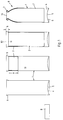
- Figur 1 eine geschnittene Draufsicht auf eine Zweikammer-Druckpackung in verschiedenen Stufen des Verfahrens zu ihrer Herstellung gemäß dem Stand der Technik nach der EP-A 0 326 052;
- Figur 2 eine geschnittene Draufsicht auf eine Zweikammer-Druckpackung in verschiedenen Stufen des Verfahrens zu ihrer Herstellung nach der vorliegenden Erfindung;
- Figur 3 eine teilweise geschnittene Draufsicht auf ein erfindungsgemäßes Nachrollwerkzeug.
- Eine Zweikammer-Druckpackung R besteht gemäß Figur 1 aus einer Außenhülle 1 sowie einem Innenkörper 2. Der Innenkörper 2 ist nur in einem bestimmten oberen Bereich a über eine Haftvermittlerschicht 3 mit der Außenhülle 1 verbunden. Ansonsten ist zwischen Innenkörper 2 und Außenhülle 1 ein Innenraum 4 ausgebildet, der mit einem Druckmedium durch ein Loch 5 in einem gewölbten Boden 6 gefüllt ist.
- Der Innenkörper 2 dient zur Aufnahme eines aus einem der Übersichtlichkeit halber nicht gezeigten Ventil auszubringenden Produktes. Dieses Ventil bzw. ein Ventildeckel, in dem das Ventil sitzt, wird auf einen Bördelrand 7 aufgesetzt.
- Die Herstellung dieser Zweikammer-Druckpackung R geschieht entsprechend der EP-A 0 326 052 und der Figur 1 folgendermaßen:
- Aus einer Metallronde 8, insbesondere aus einer Aluminiumronde, wird die Außenhülle 1 gezogen. Beispielsweise geschieht dies durch einen bekannten Tiefzieh- bzw. Fließpreßvorgang. Während des Vorganges oder danach wird gleichzeitig auch der Boden 6 aufgewölbt und das Bodenloch 5 entweder ausgestanzt oder aber nur vorgestanzt, so daß bei letzgenanntem Fall durch ein späteres Unterdrucksetzen des Bodens 6 eine angestanzte Ronde ausgedrückt und das Loch 5 hergestellt wird. Der Boden 6 muß im übrigen nicht aufgewölbt sein, er kann auch flach bleiben. Allerdings hat sich ein aufgewölbter Boden 6 bei Druckbeaufschlagung des Innenraumes 4 als günstiger erwiesen.
- Ferner wird ein Randbereich 9 der Außenhülle 1 aufgeweitet, um die Außenhülle 1 in einem weiteren Arbeitsschritt besser auf einen Dorn aufstecken zu können.
- Danach wird ein Haftvermittler in einem Bereich a auf eine Außenfläche 10 der Innenhülle 1 oder Außenfläche des Innenkörpers 2 aufgebracht, beispielsweise aufgesprüht. Als Haftvermittler können verschiedene Klebstoffe oder Kunststoffe in Betracht kommen.
- In einer weiteren Arbeitsstufe erfolgt das Einbringen bzw. Herstellen des Innenkörpers 2. Dieser Innenkörper 2 besteht aus einem beliebigen dünnen, knautschbaren Material, wie beispielsweise einem Kunststoff oder einer dünnen Metallinsbesondere Aluminiumfolie. Dieser Innenkörper 2 kann als Ganzes in die Außenhülle 1 eingebracht werden, oder aber er wird eingesprüht, eingefüllt od. dgl.. Hier gibt es ebenfalls viele Methoden, die von der vorliegenden Erfindung umfaßt sind.
- In jedem Fall wird der Innenkörper 2 durch die Haftvermittlerschicht 3 im Bereich a an der Außenhülle 1 festgelegt, während er ansonsten im Inneren der Außenhülle 1 nicht mit der Innenfläche 10 verbunden ist.
- Wird nach Druckbeaufschlagung des Innenraumes 4 ein in dem Innenkörper 2 befindliches Produkt durch ein Ventil ausgebracht, so wird dieser Innenkörper 2 unter dem Druck in dem Innenraum 4 zusammengepreßt und geknautscht, so daß sich das Volumen des Innenraumes 4 erhöht und das Volumen des Innenkörpers 2 vermindert. Hierdurch wird das Produkt aus dem Ventil ausgepreßt.
- Ein Rand 11 des Innenkörpers 2 endet in einem Abstand b von einem Oeffnungsrand 12 der Außenhülle 1. In diesem Abstand b befindet sich weder ein Haftvermittler noch Material des Innenkörpers 2.
- In einem bekannten üblichen Bördelwerkzeug erfolgt nun ein Einziehen des oberen Teils der Außenhülle 1 zusammen mit dem Innenkörper 2 im Bereich eines Teils der Haftvermittlerschicht 3. Danach wird der Teil der Außenhülle 1 zwischen Rand 11 und Öffnungsrand 12 und noch ein Teil des sich daran anschließenden Haftvermittlerbereiches 3 nach außen oder nach innen umgelegt und zu einem Bördelrand 7 geformt.
- Nach diesem Herstellungsverfahren kann in den Innenkörper 2 das auszubringende Produkt eingefüllt und eine Oeffnung 13 der Zweikammer-Druckpackung R mit einem Ventil verschlossen werden. Nun wird auch der Innenraum 4 durch das Loch 5 hindurch mit Druck beaufschlagt, wobei ggfs. eine vorgestanzte Ronde aus dem Loch 5 durch diese Druckbeaufschlagung des Innenraumes 4 herausgebrochen wird.
- Von diesem Verfahren nach dem Stand der Technik unterscheidet sich das erfindungsgemäße Verfahren wie folgt:
- Nach dem Einbringen oder Herstellen des Innenkörpers 2 in der Außenhülle 1 und die Verbindung von Innenkörper 2 mit der Haftvermittlerschicht 3 wird ein oberer Ring 14 anschließend an den Öffnungsrand 12 bevorzugt bis zum Rand 11 oder sogar darüber hinaus entfernt. Das Entfernen geschieht bevorzugt durch Fräsen, jedoch sind auch andere Möglichkeiten, wie Schneiden, denkbar.
- Im vorliegenden Ausführungsbeispiel ist dieser Ring 14 noch aufgeweitet. Dies ist jedoch nicht unbedingt notwendig, da eine Aufweitung in diesem Sinne für das weitere Verfahren nicht unbedingt nötig ist.
- Nach dem Entfernen des Ringes 14 wird die Außenhülle 1 zusammen mit dem Innenkörper 2, wie bekannt, eingezogen und der Bördelrand 7 hergestellt. Das Einziehen geschieht dabei durch eine im Verhältnis zum Stand der Technik höhere Anzahl von Ziehstufen, wobei eine Faltenbildung und damit Leckagen zwischen Außenhülle 1 und Innenkörper 2 vermieden wird.
- Da das Herstellen des Bördelrandes 7 im Bereich der Haftvermittlerschicht 3 erfolgt, hat es sich in der Praxis gezeigt, daß der Innenkörper 2 und auch die Haftvermittlerschicht 3 im Bereich des offenen Bördelrandes 7 unschön zackenartig oder fetzenartig ausgeformt ist. Aus diesem Grunde sollte ein Nachrollen durchgeführt werden, was mit einem Nachrollwerkzeug E geschieht. Dieses Nachrollwerkzeug E weist gemäß Figur 3 einen Rollring 15 mit einer Umfangsnut 16 für den Bördelrand 7 der Zweikammer-Druckpackung 8 auf. Die Umfangsnut 16 besitzt eine Kontur, welche der Kontur des Bördelrandes 7 nachempfunden ist.
- Der Rollring 15 sitzt mit einem Kugellager 17 einer Welle 18 auf, die in einen Wellenblock 19 eingeschraubt und durch eine Mutter 20 gesichert ist.
Claims (4)
- Verfahren zum Herstelen einer Zweikammer-Druckpackung (R) mit einer Außenhülle (1), mit der im Bereich einer Haftvermittlerschicht (3) ein Innenkörper (2) aus faltenbildendem bzw. knautschbarem Material verbunden wird, wobei Außenhülle (1), Haftvermittlerschicht (3) und Innenkörper (3) um eine Öffnung (13) gemeinsam zu einem Bördelrand (7) umgelegt werden,
dadurch gekennzeichnet,
daß von der Außenhülle (1) und ggfs. dem Innenkörper (2) vor dem Umlegen zu einem Bördelrand (7) ein Ring (14) entfernt wird. - Verfahren nach Anspruch 1, dadurch gekennzeichnet, daß der Ring (14) abgefräst wird.
- Verfahren nach Anspruch 1 oder 2, dadurch gekennzeichnet, daß der zu entfernende Ring (14) sich zwischen einem Öffnungsrad (12) der Außenhülle (1) und zumindest einem Rand (11) von Haftvermittlerschicht (3) und/oder Innenkörper (2) erstreckt.
- Verfahren nach einem der Ansprüche 1 bis 3, dadurch gekennzeichnet, daß der Bördelrand (7) nachgerollt wird.
Priority Applications (5)
| Application Number | Priority Date | Filing Date | Title |
|---|---|---|---|
| ES95107633T ES2130465T3 (es) | 1995-05-19 | 1995-05-19 | Procedimiento para la fabricacion de un envase a presion de doble camara. |
| AT95107633T ATE179132T1 (de) | 1995-05-19 | 1995-05-19 | Verfahren zum herstellen einer zweikammer- druckpackung |
| EP95107633A EP0743255B1 (de) | 1995-05-19 | 1995-05-19 | Verfahren zum Herstellen einer Zweikammer-Druckpackung |
| DK95107633T DK0743255T3 (da) | 1995-05-19 | 1995-05-19 | Fremgangsmåde til fremstilling af en tokammer-trykemballage |
| GR990401867T GR3030780T3 (en) | 1995-05-19 | 1999-07-14 | Method to produce a dual-compartment pressurized pack |
Applications Claiming Priority (1)
| Application Number | Priority Date | Filing Date | Title |
|---|---|---|---|
| EP95107633A EP0743255B1 (de) | 1995-05-19 | 1995-05-19 | Verfahren zum Herstellen einer Zweikammer-Druckpackung |
Publications (2)
| Publication Number | Publication Date |
|---|---|
| EP0743255A1 true EP0743255A1 (de) | 1996-11-20 |
| EP0743255B1 EP0743255B1 (de) | 1999-04-21 |
Family
ID=8219262
Family Applications (1)
| Application Number | Title | Priority Date | Filing Date |
|---|---|---|---|
| EP95107633A Expired - Lifetime EP0743255B1 (de) | 1995-05-19 | 1995-05-19 | Verfahren zum Herstellen einer Zweikammer-Druckpackung |
Country Status (5)
| Country | Link |
|---|---|
| EP (1) | EP0743255B1 (de) |
| AT (1) | ATE179132T1 (de) |
| DK (1) | DK0743255T3 (de) |
| ES (1) | ES2130465T3 (de) |
| GR (1) | GR3030780T3 (de) |
Cited By (2)
| Publication number | Priority date | Publication date | Assignee | Title |
|---|---|---|---|---|
| US10239648B2 (en) | 2014-10-28 | 2019-03-26 | Ball Metalpack, Llc | Apparatus and method for forming a cup with a reformed bottom |
| US10315242B2 (en) | 2014-10-15 | 2019-06-11 | Ball Metalpack, Llc | Apparatus and method for simultaneously forming a contoured shoulder and neck portion in a closed end of a metallic container |
Citations (4)
| Publication number | Priority date | Publication date | Assignee | Title |
|---|---|---|---|---|
| US2239696A (en) * | 1936-05-29 | 1941-04-29 | Mullins Mfg Corp | Method and apparatus for forming the rims of cylindrical shells |
| EP0326052A2 (de) * | 1988-01-27 | 1989-08-02 | Gerd Stoffel | Verfahren zum Herstellen einer Zweikammer-Druckkammer |
| EP0469774A1 (de) * | 1990-07-28 | 1992-02-05 | CarnaudMetalbox plc | Verfahren zur Herstellung einer Dose mit gezogenen Wänden |
| EP0547982A1 (de) * | 1991-12-17 | 1993-06-23 | Cebal S.A. | Verfahren zur Herstellung eines Sprühdosenkörpers mit einem metallischen Innenbehälter sowie Sprühdosenkörper und entsprechende Sprühdose |
-
1995
- 1995-05-19 DK DK95107633T patent/DK0743255T3/da active
- 1995-05-19 ES ES95107633T patent/ES2130465T3/es not_active Expired - Lifetime
- 1995-05-19 EP EP95107633A patent/EP0743255B1/de not_active Expired - Lifetime
- 1995-05-19 AT AT95107633T patent/ATE179132T1/de not_active IP Right Cessation
-
1999
- 1999-07-14 GR GR990401867T patent/GR3030780T3/el unknown
Patent Citations (4)
| Publication number | Priority date | Publication date | Assignee | Title |
|---|---|---|---|---|
| US2239696A (en) * | 1936-05-29 | 1941-04-29 | Mullins Mfg Corp | Method and apparatus for forming the rims of cylindrical shells |
| EP0326052A2 (de) * | 1988-01-27 | 1989-08-02 | Gerd Stoffel | Verfahren zum Herstellen einer Zweikammer-Druckkammer |
| EP0469774A1 (de) * | 1990-07-28 | 1992-02-05 | CarnaudMetalbox plc | Verfahren zur Herstellung einer Dose mit gezogenen Wänden |
| EP0547982A1 (de) * | 1991-12-17 | 1993-06-23 | Cebal S.A. | Verfahren zur Herstellung eines Sprühdosenkörpers mit einem metallischen Innenbehälter sowie Sprühdosenkörper und entsprechende Sprühdose |
Cited By (2)
| Publication number | Priority date | Publication date | Assignee | Title |
|---|---|---|---|---|
| US10315242B2 (en) | 2014-10-15 | 2019-06-11 | Ball Metalpack, Llc | Apparatus and method for simultaneously forming a contoured shoulder and neck portion in a closed end of a metallic container |
| US10239648B2 (en) | 2014-10-28 | 2019-03-26 | Ball Metalpack, Llc | Apparatus and method for forming a cup with a reformed bottom |
Also Published As
| Publication number | Publication date |
|---|---|
| ES2130465T3 (es) | 1999-07-01 |
| DK0743255T3 (da) | 1999-10-25 |
| ATE179132T1 (de) | 1999-05-15 |
| GR3030780T3 (en) | 1999-11-30 |
| EP0743255B1 (de) | 1999-04-21 |
Similar Documents
| Publication | Publication Date | Title |
|---|---|---|
| DE3802314C1 (de) | ||
| DE60201504T2 (de) | Verfahren und vorrichtung zum einhalsen der öffnung eines behälters | |
| DE2409912B2 (de) | Verfahren zum Einsetzen eines topfförmigen metallischen Bodens in einem metallischen Behälterkörper | |
| DE3204946A1 (de) | Behaelter | |
| EP2426080A1 (de) | Verfahren und Werkzeug zur Herstellung eines Trichters, Trichter und Behälter mit Trichter | |
| DE4413331B4 (de) | Verfahren zum Herstellen einer Zweikammer-Druckpackung | |
| EP3401032B1 (de) | Verbundwerkzeug und verfahren zur herstellung eines blechbauteils | |
| DE60125580T2 (de) | Aerosoldosenenden | |
| WO2006048302A1 (de) | Verfahren zum umformen einer grossflächigen blechplatine zu einem formteil, wie einem aussenhautteil einer kraftfahrzeugkarosserie | |
| DE3322977A1 (de) | Papierbehaelter fuer heiss abfuellbare fluessigkeiten | |
| EP0740969A1 (de) | Verfahren zur Herstellung eines Blechhohlkörpers mit komplizierter Form | |
| EP0743255B1 (de) | Verfahren zum Herstellen einer Zweikammer-Druckpackung | |
| DE1452542A1 (de) | Leichtmetall-Verschlusskappe und Verfahren zu ihrer Herstellung | |
| DE10258445A1 (de) | Hochdruckspeicherbehälter und Verfahren zur Herstellung desselben | |
| DE3229246A1 (de) | Verfahren und vorrichtung zum abstreifen eines randflansches waehrend des behaelternachziehens | |
| EP1268099B1 (de) | Verfahren zum herstellen von bauteilen mittels eines fliessfähigen wirkmediums sowie eines formwerkzeugs | |
| DE10261534A1 (de) | Spraydose | |
| EP0004252B1 (de) | Verfahren zur Herstellung eines Aerosoltrichters | |
| EP1207974A1 (de) | Tiefziehverfahren und tiefziehwerkzeug | |
| DE3915765C2 (de) | Verfahren zum Herstellen einer Zweikammer-Druckpackung | |
| DE2816860A1 (de) | Verfahren zur herstellung eines aerosoltrichters | |
| EP0980726A2 (de) | Verfahren zur Herstellung eines verschliessbaren Behälters | |
| AT267351B (de) | Metallische Aufreißkappe aus dünnem Material und Verfahren zu ihrer Herstellung | |
| DE3106349A1 (de) | Verfahren und vorrichtung zur herstellung von metallfaessern | |
| EP4101558A1 (de) | Verfahren zur herstellung eines aerosoldoms |
Legal Events
| Date | Code | Title | Description |
|---|---|---|---|
| PUAI | Public reference made under article 153(3) epc to a published international application that has entered the european phase |
Free format text: ORIGINAL CODE: 0009012 |
|
| AK | Designated contracting states |
Kind code of ref document: A1 Designated state(s): AT BE CH DK ES FR GB GR IE IT LI LU MC NL PT SE |
|
| 17P | Request for examination filed |
Effective date: 19970424 |
|
| 17Q | First examination report despatched |
Effective date: 19980409 |
|
| GRAG | Despatch of communication of intention to grant |
Free format text: ORIGINAL CODE: EPIDOS AGRA |
|
| GRAG | Despatch of communication of intention to grant |
Free format text: ORIGINAL CODE: EPIDOS AGRA |
|
| GRAH | Despatch of communication of intention to grant a patent |
Free format text: ORIGINAL CODE: EPIDOS IGRA |
|
| GRAH | Despatch of communication of intention to grant a patent |
Free format text: ORIGINAL CODE: EPIDOS IGRA |
|
| GRAA | (expected) grant |
Free format text: ORIGINAL CODE: 0009210 |
|
| AK | Designated contracting states |
Kind code of ref document: B1 Designated state(s): AT BE CH DK ES FR GB GR IE IT LI LU MC NL PT SE |
|
| REF | Corresponds to: |
Ref document number: 179132 Country of ref document: AT Date of ref document: 19990515 Kind code of ref document: T |
|
| REG | Reference to a national code |
Ref country code: CH Ref legal event code: NV Representative=s name: FREI PATENTANWALTSBUERO Ref country code: CH Ref legal event code: EP |
|
| PG25 | Lapsed in a contracting state [announced via postgrant information from national office to epo] |
Ref country code: LU Free format text: LAPSE BECAUSE OF NON-PAYMENT OF DUE FEES Effective date: 19990519 |
|
| REG | Reference to a national code |
Ref country code: IE Ref legal event code: FG4D Free format text: GERMAN |
|
| GBT | Gb: translation of ep patent filed (gb section 77(6)(a)/1977) |
Effective date: 19990602 |
|
| REG | Reference to a national code |
Ref country code: ES Ref legal event code: FG2A Ref document number: 2130465 Country of ref document: ES Kind code of ref document: T3 |
|
| ET | Fr: translation filed | ||
| REG | Reference to a national code |
Ref country code: DK Ref legal event code: T3 |
|
| REG | Reference to a national code |
Ref country code: PT Ref legal event code: SC4A Free format text: AVAILABILITY OF NATIONAL TRANSLATION Effective date: 19990721 |
|
| PG25 | Lapsed in a contracting state [announced via postgrant information from national office to epo] |
Ref country code: MC Free format text: LAPSE BECAUSE OF NON-PAYMENT OF DUE FEES Effective date: 19991130 |
|
| REG | Reference to a national code |
Ref country code: IE Ref legal event code: FD4D |
|
| PLBE | No opposition filed within time limit |
Free format text: ORIGINAL CODE: 0009261 |
|
| STAA | Information on the status of an ep patent application or granted ep patent |
Free format text: STATUS: NO OPPOSITION FILED WITHIN TIME LIMIT |
|
| 26N | No opposition filed | ||
| REG | Reference to a national code |
Ref country code: GB Ref legal event code: IF02 |
|
| PGFP | Annual fee paid to national office [announced via postgrant information from national office to epo] |
Ref country code: PT Payment date: 20040419 Year of fee payment: 10 |
|
| PGFP | Annual fee paid to national office [announced via postgrant information from national office to epo] |
Ref country code: GR Payment date: 20040423 Year of fee payment: 10 |
|
| PGFP | Annual fee paid to national office [announced via postgrant information from national office to epo] |
Ref country code: GB Payment date: 20040427 Year of fee payment: 10 |
|
| PGFP | Annual fee paid to national office [announced via postgrant information from national office to epo] |
Ref country code: NL Payment date: 20040429 Year of fee payment: 10 Ref country code: CH Payment date: 20040429 Year of fee payment: 10 |
|
| PGFP | Annual fee paid to national office [announced via postgrant information from national office to epo] |
Ref country code: SE Payment date: 20040504 Year of fee payment: 10 |
|
| PGFP | Annual fee paid to national office [announced via postgrant information from national office to epo] |
Ref country code: DK Payment date: 20040505 Year of fee payment: 10 Ref country code: AT Payment date: 20040505 Year of fee payment: 10 |
|
| PGFP | Annual fee paid to national office [announced via postgrant information from national office to epo] |
Ref country code: FR Payment date: 20040512 Year of fee payment: 10 |
|
| PGFP | Annual fee paid to national office [announced via postgrant information from national office to epo] |
Ref country code: ES Payment date: 20040518 Year of fee payment: 10 |
|
| PGFP | Annual fee paid to national office [announced via postgrant information from national office to epo] |
Ref country code: BE Payment date: 20040608 Year of fee payment: 10 |
|
| PG25 | Lapsed in a contracting state [announced via postgrant information from national office to epo] |
Ref country code: IT Free format text: LAPSE BECAUSE OF NON-PAYMENT OF DUE FEES Effective date: 20050519 Ref country code: GB Free format text: LAPSE BECAUSE OF NON-PAYMENT OF DUE FEES Effective date: 20050519 Ref country code: AT Free format text: LAPSE BECAUSE OF NON-PAYMENT OF DUE FEES Effective date: 20050519 |
|
| PG25 | Lapsed in a contracting state [announced via postgrant information from national office to epo] |
Ref country code: SE Free format text: LAPSE BECAUSE OF NON-PAYMENT OF DUE FEES Effective date: 20050520 Ref country code: ES Free format text: LAPSE BECAUSE OF NON-PAYMENT OF DUE FEES Effective date: 20050520 |
|
| PG25 | Lapsed in a contracting state [announced via postgrant information from national office to epo] |
Ref country code: LI Free format text: LAPSE BECAUSE OF NON-PAYMENT OF DUE FEES Effective date: 20050531 Ref country code: DK Free format text: LAPSE BECAUSE OF NON-PAYMENT OF DUE FEES Effective date: 20050531 Ref country code: CH Free format text: LAPSE BECAUSE OF NON-PAYMENT OF DUE FEES Effective date: 20050531 Ref country code: BE Free format text: LAPSE BECAUSE OF NON-PAYMENT OF DUE FEES Effective date: 20050531 |
|
| PG25 | Lapsed in a contracting state [announced via postgrant information from national office to epo] |
Ref country code: PT Free format text: LAPSE BECAUSE OF NON-PAYMENT OF DUE FEES Effective date: 20051121 |
|
| BERE | Be: lapsed |
Owner name: *STOFFEL GERD Effective date: 20050531 |
|
| PG25 | Lapsed in a contracting state [announced via postgrant information from national office to epo] |
Ref country code: NL Free format text: LAPSE BECAUSE OF NON-PAYMENT OF DUE FEES Effective date: 20051201 |
|
| PG25 | Lapsed in a contracting state [announced via postgrant information from national office to epo] |
Ref country code: GR Free format text: LAPSE BECAUSE OF NON-PAYMENT OF DUE FEES Effective date: 20051205 |
|
| REG | Reference to a national code |
Ref country code: CH Ref legal event code: PL |
|
| EUG | Se: european patent has lapsed | ||
| GBPC | Gb: european patent ceased through non-payment of renewal fee |
Effective date: 20050519 |
|
| PG25 | Lapsed in a contracting state [announced via postgrant information from national office to epo] |
Ref country code: FR Free format text: LAPSE BECAUSE OF NON-PAYMENT OF DUE FEES Effective date: 20060131 |
|
| NLV4 | Nl: lapsed or anulled due to non-payment of the annual fee |
Effective date: 20051201 |
|
| REG | Reference to a national code |
Ref country code: DK Ref legal event code: EBP |
|
| REG | Reference to a national code |
Ref country code: FR Ref legal event code: ST Effective date: 20060131 |
|
| REG | Reference to a national code |
Ref country code: ES Ref legal event code: FD2A Effective date: 20050520 |
|
| BERE | Be: lapsed |
Owner name: *STOFFEL GERD Effective date: 20050531 |