EP0742863B1 - Befestigungselement mit schraubengewinde - Google Patents
Befestigungselement mit schraubengewinde Download PDFInfo
- Publication number
- EP0742863B1 EP0742863B1 EP96900314A EP96900314A EP0742863B1 EP 0742863 B1 EP0742863 B1 EP 0742863B1 EP 96900314 A EP96900314 A EP 96900314A EP 96900314 A EP96900314 A EP 96900314A EP 0742863 B1 EP0742863 B1 EP 0742863B1
- Authority
- EP
- European Patent Office
- Prior art keywords
- expanding
- fastener according
- screw
- base flange
- guide member
- Prior art date
- Legal status (The legal status is an assumption and is not a legal conclusion. Google has not performed a legal analysis and makes no representation as to the accuracy of the status listed.)
- Expired - Lifetime
Links
- 230000002093 peripheral effect Effects 0.000 claims abstract description 7
- 230000000284 resting effect Effects 0.000 claims description 3
- 230000000149 penetrating effect Effects 0.000 claims description 2
- 230000002787 reinforcement Effects 0.000 description 5
- 210000002105 tongue Anatomy 0.000 description 4
- 238000009434 installation Methods 0.000 description 3
- 239000011122 softwood Substances 0.000 description 2
- 230000002542 deteriorative effect Effects 0.000 description 1
- 238000007373 indentation Methods 0.000 description 1
- 238000005304 joining Methods 0.000 description 1
- 238000004519 manufacturing process Methods 0.000 description 1
- 239000000463 material Substances 0.000 description 1
- 238000000034 method Methods 0.000 description 1
- 238000005192 partition Methods 0.000 description 1
- 239000011343 solid material Substances 0.000 description 1
- 238000003860 storage Methods 0.000 description 1
Images


Classifications
-
- E—FIXED CONSTRUCTIONS
- E05—LOCKS; KEYS; WINDOW OR DOOR FITTINGS; SAFES
- E05B—LOCKS; ACCESSORIES THEREFOR; HANDCUFFS
- E05B3/00—Fastening knobs or handles to lock or latch parts
- E05B3/02—Fastening knobs or handles to the spindle by pinning or riveting
-
- F—MECHANICAL ENGINEERING; LIGHTING; HEATING; WEAPONS; BLASTING
- F16—ENGINEERING ELEMENTS AND UNITS; GENERAL MEASURES FOR PRODUCING AND MAINTAINING EFFECTIVE FUNCTIONING OF MACHINES OR INSTALLATIONS; THERMAL INSULATION IN GENERAL
- F16B—DEVICES FOR FASTENING OR SECURING CONSTRUCTIONAL ELEMENTS OR MACHINE PARTS TOGETHER, e.g. NAILS, BOLTS, CIRCLIPS, CLAMPS, CLIPS OR WEDGES; JOINTS OR JOINTING
- F16B13/00—Dowels or other devices fastened in walls or the like by inserting them in holes made therein for that purpose
- F16B13/04—Dowels or other devices fastened in walls or the like by inserting them in holes made therein for that purpose with parts gripping in the hole or behind the reverse side of the wall after inserting from the front
- F16B13/08—Dowels or other devices fastened in walls or the like by inserting them in holes made therein for that purpose with parts gripping in the hole or behind the reverse side of the wall after inserting from the front with separate or non-separate gripping parts moved into their final position in relation to the body of the device without further manual operation
-
- E—FIXED CONSTRUCTIONS
- E05—LOCKS; KEYS; WINDOW OR DOOR FITTINGS; SAFES
- E05B—LOCKS; ACCESSORIES THEREFOR; HANDCUFFS
- E05B1/00—Knobs or handles for wings; Knobs, handles, or press buttons for locks or latches on wings
- E05B1/0015—Knobs or handles which do not operate the bolt or lock, e.g. non-movable; Mounting thereof
-
- F—MECHANICAL ENGINEERING; LIGHTING; HEATING; WEAPONS; BLASTING
- F16—ENGINEERING ELEMENTS AND UNITS; GENERAL MEASURES FOR PRODUCING AND MAINTAINING EFFECTIVE FUNCTIONING OF MACHINES OR INSTALLATIONS; THERMAL INSULATION IN GENERAL
- F16B—DEVICES FOR FASTENING OR SECURING CONSTRUCTIONAL ELEMENTS OR MACHINE PARTS TOGETHER, e.g. NAILS, BOLTS, CIRCLIPS, CLAMPS, CLIPS OR WEDGES; JOINTS OR JOINTING
- F16B13/00—Dowels or other devices fastened in walls or the like by inserting them in holes made therein for that purpose
- F16B13/04—Dowels or other devices fastened in walls or the like by inserting them in holes made therein for that purpose with parts gripping in the hole or behind the reverse side of the wall after inserting from the front
- F16B13/06—Dowels or other devices fastened in walls or the like by inserting them in holes made therein for that purpose with parts gripping in the hole or behind the reverse side of the wall after inserting from the front combined with expanding sleeve
- F16B13/063—Dowels or other devices fastened in walls or the like by inserting them in holes made therein for that purpose with parts gripping in the hole or behind the reverse side of the wall after inserting from the front combined with expanding sleeve by the use of an expander
- F16B13/066—Dowels or other devices fastened in walls or the like by inserting them in holes made therein for that purpose with parts gripping in the hole or behind the reverse side of the wall after inserting from the front combined with expanding sleeve by the use of an expander fastened by extracting a separate expander-part, actuated by the screw, nail or the like
-
- F—MECHANICAL ENGINEERING; LIGHTING; HEATING; WEAPONS; BLASTING
- F16—ENGINEERING ELEMENTS AND UNITS; GENERAL MEASURES FOR PRODUCING AND MAINTAINING EFFECTIVE FUNCTIONING OF MACHINES OR INSTALLATIONS; THERMAL INSULATION IN GENERAL
- F16B—DEVICES FOR FASTENING OR SECURING CONSTRUCTIONAL ELEMENTS OR MACHINE PARTS TOGETHER, e.g. NAILS, BOLTS, CIRCLIPS, CLAMPS, CLIPS OR WEDGES; JOINTS OR JOINTING
- F16B13/00—Dowels or other devices fastened in walls or the like by inserting them in holes made therein for that purpose
- F16B13/04—Dowels or other devices fastened in walls or the like by inserting them in holes made therein for that purpose with parts gripping in the hole or behind the reverse side of the wall after inserting from the front
- F16B13/08—Dowels or other devices fastened in walls or the like by inserting them in holes made therein for that purpose with parts gripping in the hole or behind the reverse side of the wall after inserting from the front with separate or non-separate gripping parts moved into their final position in relation to the body of the device without further manual operation
- F16B13/0866—Dowels or other devices fastened in walls or the like by inserting them in holes made therein for that purpose with parts gripping in the hole or behind the reverse side of the wall after inserting from the front with separate or non-separate gripping parts moved into their final position in relation to the body of the device without further manual operation with prongs penetrating into the wall of the hole by a retractile movement of a threaded member
-
- F—MECHANICAL ENGINEERING; LIGHTING; HEATING; WEAPONS; BLASTING
- F16—ENGINEERING ELEMENTS AND UNITS; GENERAL MEASURES FOR PRODUCING AND MAINTAINING EFFECTIVE FUNCTIONING OF MACHINES OR INSTALLATIONS; THERMAL INSULATION IN GENERAL
- F16B—DEVICES FOR FASTENING OR SECURING CONSTRUCTIONAL ELEMENTS OR MACHINE PARTS TOGETHER, e.g. NAILS, BOLTS, CIRCLIPS, CLAMPS, CLIPS OR WEDGES; JOINTS OR JOINTING
- F16B9/00—Connections of rods or tubular parts to flat surfaces at an angle
- F16B9/05—Connections of rods or tubular parts to flat surfaces at an angle by way of an intermediate member
- F16B9/056—Connections of rods or tubular parts to flat surfaces at an angle by way of an intermediate member the intermediate member extending through the flat surface; the rod or tubular part extending through the flat surface
-
- F—MECHANICAL ENGINEERING; LIGHTING; HEATING; WEAPONS; BLASTING
- F16—ENGINEERING ELEMENTS AND UNITS; GENERAL MEASURES FOR PRODUCING AND MAINTAINING EFFECTIVE FUNCTIONING OF MACHINES OR INSTALLATIONS; THERMAL INSULATION IN GENERAL
- F16B—DEVICES FOR FASTENING OR SECURING CONSTRUCTIONAL ELEMENTS OR MACHINE PARTS TOGETHER, e.g. NAILS, BOLTS, CIRCLIPS, CLAMPS, CLIPS OR WEDGES; JOINTS OR JOINTING
- F16B13/00—Dowels or other devices fastened in walls or the like by inserting them in holes made therein for that purpose
- F16B13/04—Dowels or other devices fastened in walls or the like by inserting them in holes made therein for that purpose with parts gripping in the hole or behind the reverse side of the wall after inserting from the front
- F16B13/06—Dowels or other devices fastened in walls or the like by inserting them in holes made therein for that purpose with parts gripping in the hole or behind the reverse side of the wall after inserting from the front combined with expanding sleeve
- F16B13/063—Dowels or other devices fastened in walls or the like by inserting them in holes made therein for that purpose with parts gripping in the hole or behind the reverse side of the wall after inserting from the front combined with expanding sleeve by the use of an expander
- F16B13/065—Dowels or other devices fastened in walls or the like by inserting them in holes made therein for that purpose with parts gripping in the hole or behind the reverse side of the wall after inserting from the front combined with expanding sleeve by the use of an expander fastened by extracting the screw, nail or the like
-
- F—MECHANICAL ENGINEERING; LIGHTING; HEATING; WEAPONS; BLASTING
- F16—ENGINEERING ELEMENTS AND UNITS; GENERAL MEASURES FOR PRODUCING AND MAINTAINING EFFECTIVE FUNCTIONING OF MACHINES OR INSTALLATIONS; THERMAL INSULATION IN GENERAL
- F16B—DEVICES FOR FASTENING OR SECURING CONSTRUCTIONAL ELEMENTS OR MACHINE PARTS TOGETHER, e.g. NAILS, BOLTS, CIRCLIPS, CLAMPS, CLIPS OR WEDGES; JOINTS OR JOINTING
- F16B2200/00—Constructional details of connections not covered for in other groups of this subclass
- F16B2200/40—Clamping arrangements where clamping parts are received in recesses of elements to be connected
-
- F—MECHANICAL ENGINEERING; LIGHTING; HEATING; WEAPONS; BLASTING
- F16—ENGINEERING ELEMENTS AND UNITS; GENERAL MEASURES FOR PRODUCING AND MAINTAINING EFFECTIVE FUNCTIONING OF MACHINES OR INSTALLATIONS; THERMAL INSULATION IN GENERAL
- F16B—DEVICES FOR FASTENING OR SECURING CONSTRUCTIONAL ELEMENTS OR MACHINE PARTS TOGETHER, e.g. NAILS, BOLTS, CIRCLIPS, CLAMPS, CLIPS OR WEDGES; JOINTS OR JOINTING
- F16B9/00—Connections of rods or tubular parts to flat surfaces at an angle
- F16B9/02—Detachable connections
-
- Y—GENERAL TAGGING OF NEW TECHNOLOGICAL DEVELOPMENTS; GENERAL TAGGING OF CROSS-SECTIONAL TECHNOLOGIES SPANNING OVER SEVERAL SECTIONS OF THE IPC; TECHNICAL SUBJECTS COVERED BY FORMER USPC CROSS-REFERENCE ART COLLECTIONS [XRACs] AND DIGESTS
- Y10—TECHNICAL SUBJECTS COVERED BY FORMER USPC
- Y10T—TECHNICAL SUBJECTS COVERED BY FORMER US CLASSIFICATION
- Y10T403/00—Joints and connections
- Y10T403/46—Rod end to transverse side of member
-
- Y—GENERAL TAGGING OF NEW TECHNOLOGICAL DEVELOPMENTS; GENERAL TAGGING OF CROSS-SECTIONAL TECHNOLOGIES SPANNING OVER SEVERAL SECTIONS OF THE IPC; TECHNICAL SUBJECTS COVERED BY FORMER USPC CROSS-REFERENCE ART COLLECTIONS [XRACs] AND DIGESTS
- Y10—TECHNICAL SUBJECTS COVERED BY FORMER USPC
- Y10T—TECHNICAL SUBJECTS COVERED BY FORMER US CLASSIFICATION
- Y10T403/00—Joints and connections
- Y10T403/70—Interfitted members
- Y10T403/7041—Interfitted members including set screw
Definitions
- the present invention relates to a screw fastener according to the preamble of claim 1.
- Fastening means of this type are required for mounting curved handles provided with hollow ends on a contact face of a door, a window, a drawer of the like, fixing being achieved by means of expanding parts which are secured relative to one another in a hole by means of a screw.
- curved handles in this way, for example on house doors; normal ironmongery is generaly mounted on the interior of the door.
- coverings are generally required on the interior of the door, for example a blind round anchor plate or covering cap, to make the otherwise visible screw fastener as unnoticeable as possible.
- FR-A-2 612 577 describes handle fixing means that comprise a tensioning through-bolt which passes a hollow door frame transversely and is engaged by base rings as well as securing nut sleeves on either side of the door for attaching handles to it. As the nuts are tightened, the hollow door frame is likely to be squeezed and deformed on either side; a partition line is visible between each base ring and the securing nut joining it.
- Anchorage should take place quickly and reliably without covering elements being required on the interior of the door. It should also be possible without problems to provide an axially firm rotatable connection to a door handle.
- the invention is characterized by a guide member receiving the screw and comprising a base flange for resting on a contact face of a door or the like, part of the guide member, together with said expanding parts connected to said guide member for expansion by said screw, being securably receivable in a blind orifice of a door or the like, the base flange being releasably connectable to a supporting member connectable in use rigidly or detachably to a hollow end of a curved handle.
- a mounting set of this type consists of few components which are inexpensive to produce and can be arranged exactly in a short spell of time. It is important for the guide member to provide the support on a contact face by the base flange so the curved handle would not directly be pressed onto the contact face; thus damage to the latter is prevented.
- anchorage is effected via the base flange on the contact face behind or beneath which the expanding parts are secured by the screw which passes through the guide member.
- the supporting member is preferably held detachably thereon and, in turn, is preferably welded to the curved handle end in order to absorb the forces and moments occurring during use of the handle.
- the supporting member positively overlaps the base flange of the guide member, fixing thus being particularly secure.
- the supporting member is a tube having a collar with a peripheral shoulder and an orifice which is axially opposed thereto and through which the fastening screw can be adjusted if necessary.
- a head is integrally connected to the base flange on the supporting body side, the head being provided with an external thread for holding a cap nut which is overlapped by the supporting member according to claim 5.
- the invention also proposes that the head and cap nut be designed integrally so as to simplify production and storage.
- the guide member has an orifice which axially guides the screw and of which the end can be screwed into an expanding part.
- the screw head is preferably received in a recess provided on the head and/or on the cap nut on the supporting body side according to claim 7.
- the head and/or the cap nut has, at an axial distance from the base flange, a peripheral notch, in particular a V-shaped groove in which a setscrew radially penetrating the hollow end and the supporting member engages to fix the hollow end. This allows rapid release of the connection, if necessary, e.g. to exchange or adjust a curved handle.
- the guide member has a shank issuing from the base flange with a conical end which can be pulled by the screw into an expanding part which is thus widened.
- the shank has an external thread on to which a broad-threaded tube can be screwed which, has an external broad thread, this being very advantageous for mounting the curved handle on a softwood surface.
- an expanding nut can be used as expanding part which has a cylindrical base with an internal thread and an expanding basket which is open towards the base flange and is preferably provided with wedge faces.
- the conical end of the shank acts on the wedge faces when the screw is being turned in and therefore presses individual tongues of the expanding basket into the orifice.
- the expanding part may be a tube having an expanding basket which is open remotely from the base flange, is preferably provided with wedge faces and can be widened by a conical nut directed away from it.
- the screw engages therein so the tubular basket expands and its tongues engage behind an internal contact face.
- the base flange has a recess for the positive holding and supporting of a top bush of the expanding tube, allowing particularly reliable fixing.
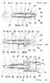
- Fig. 1 shows a cap nut 20 with a head 22 having two parallel wrench faces 23 and a peripheral recess in the form of a V-shaped groove 24.
- a shoulder 25 is provided on a supporting flange 26 axially remote from the head 22.
- a blind aperture 27 directed from the flange 26 to the head 22 has an internal thread 28.
- a further component of the mounting set shown in fig. 1 is a flat head screw 29 which can be introduced into a guide member 30 with an aperture 34 and can rest with its head on a recess 35 in the guide member 30.
- the guide member has a head 32 with two parallel wrench faces 33 and an external thread 36.
- a base flange 31 joined the external thread 36 and continues with a shank 37 bearing an external thread 38 and having a conical end 39.
- a broad-threaded tube 44 with an internal thread 46 can be screwed onto the external thread 38 of the shank 37.
- a further component of the mounting set in Fig. 1 is an expanding nut 40 having a cylindrical base 41 with internal thread and a gripping cone or expanding basket 42.
- the expanding basket 42 has tongues which are separated by axial slots and of which the free ends have wedge faces 43.
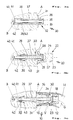
- FIG. 2a to 2c Individual mounting stages are shown in Fig. 2a to 2c.
- An orifice B with a step-shaped enlargement E is introduced into a contact member, for example a door, initially perpendicularly to the contact face A.
- a pre-assembled unit consisting of guide member 30 with the broad-threaded tube 44, of inserted screw 20 and of expanding nut 40 is inserted into the stepped orifice B, E according to Fig. 2a.
- cap nut 22 can be screwed by its internal thread 28 onto the external thread 36 of head 32.
- the screw 29 should previously have been tightened sufficiently for the expanding basket 42 with the wedge faces 43 to slide onto the conical end 39 of the shank 37 and to thus press the tongues of the expanding basket into the wall of orifice B. It is also possible to provide the cap nut 22 with a cut 67 indicated in broken lines in Fig. 2b so that a rotating tool can be applied to the head of the screw 29.
- a supporting member 12 having a collar 14 and an external shoulder 16 and - facing the cap nut head 22 - an aperture 18.
- the hollow end H of a curved handle G rests on the shoulder 16 of the supporting member 12 of which the collar overlaps the flanges 26, 31 of cap nut 20 and guide member 30.
- a transverse setscrew V fixes the hollow end H together with supporting member 12 on the V-shaped groove 24 of the cap nut 20.
- FIGs. 3a to 3c A comparable but simplified embodiment is shown in Figs. 3a to 3c.
- the mounting set used here has components similar to the embodiment in Fig. 2a to 2c but the broad-threaded tube 44 is dispensed with for fastening on harder material as proposed here.
- a smooth orifice B without a stepped enlargement (E) consequently suffices.
- the screw 29 After introduction of the guide member 30 together with screw 29 and expanding nut 40 into the orifice B (Fig 3a), the screw 29 is tightened and the expanding basket 42 therefore enlarged; the cap nut 20 can then be screwed on (Fig. 3b).
- the supporting member 12 with its collar 14 overlaps the base flange 31, the hollow end H of a curved handle G resting on the shoulder 16 and being fixed by means of the transverse setscrew V.
- the V-shaped groove 24 may have a flatter groove base, providing a larger cross section for cap nut 22 or for guide member 30 in order to minimize the risk of breakage.
- the tip of the setscrew V may be suitably rounded or flattened.
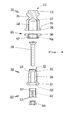
- the embodiment according to Fig. 4 is used for fastening on a multi-chamber profile M consisting of an external tubular frame R and an internal frame I.
- the latter can be provided with a reinforcement P (Fig. 4a, 4c) as is normal with plastic profiles.
- the mounting set provided here for the screw fastening additionally comprises a supporting ring 55 with a flange 56 and an orifice 57 of such a width that the head of the screw 29 passes through and an internal thread 58 can be screwed to the external thread 36 of the guide member 30.
- the flange 56 has the same external diameter as the supporting flange 26 of the cap nut 20 which can also be arranged with its internal thread 28 on the external thread 36 of the head 32 and assumes the function of a counter part in the final position.
- the guide member 30 has, in its base flange 31, a recess 59 serving to hold a top bush 61 of an expanding tube 60.
- This expanding tube 60 is provided with an expanding basket 62, directed away from the base flange 31, with wedge faces 63 which slide on an opposingly directed conical nut 64 when screwed to the screw 29.
- Fig. 4a shows that a previously assembled unit of guide member 30, screw 29, expanding tube 60 and conical nut 64 is introduced through an orifice 65 on the outer tubular frame R in such a way that the base flange 31 rests on the reinforcement P on the internal frame I.
- the supporting ring 55 is then screwed on to the head 32 until the flange 56 rests flush on the tubular frame R (Fig. 4a).
- the screw 29 can now be tightened so that the conical nut 64 widens the expanding basket 62 and therefore fixes the unit onto the internal frame I.
- the cap nut 20 is then screwed to the head 32, securing the fastener in the manner of a counter part.
- the supporting member 12 which is slipped on overlaps the two flanges 31, 26 with its collar 14 and is in turn overlapped by the hollow end H of the curved handle G until it strikes the shoulder 16.
- the transverse setscrew V holds the end H of the curved handle (Fig. 4b).
- the invention is not restricted to the illustrated designs and embodiments, It is important that single-sided curved handle fastening is provided, in particular, on doors or multi-chamber profiles M without covering elements, the holding of the supporting member 12 being effected by head 32 of guide member 30 - preferably with interposition of cap nut 20.
- the hollow end H of the curved handle G rests directly or indirectly on base flange 31 but not on the contact face A itself so no marring will occur on the surface of door or frame during use of the handle.
- tube 44 threaded for woodwork offers additional security of connection.
- an internal frame I or a reinforcement P acts as a support for the screw fastener which is therefore also secured deep inside, specifically without cold bridges.
- Partial pre-assembly is possible in all cases, and when appropriately mounted the external visible faces will not be altered or damaged.
- the screw fastening system according to the invention is also suitable for connection to an internal door handle, in which case no covering elements are required except for the shield (for its conventional contact plate).
- a guide member 30 for a screw 29 has a base flange 31 which can be connected to expanding part 39, 40, 60, 64 and on which a tubular supporting member 12 is held that can advantageously be welded into the hollow end H.
- a cap nut 20 can be screwed that comprises a peripheral groove 24 for fixing the hollow end H by means of a setscrew V and, like the head 32, also includes wrench faces 33 or 23.
- a shank 37 of guide member 30 with cone end 39 or a conical nut 64 directed against it can be pulled into an expanding nut 40 or an expanding tube 60 by the screw 29, so that an expanding basket 42, 62 is enlarged.
Landscapes
- Engineering & Computer Science (AREA)
- General Engineering & Computer Science (AREA)
- Mechanical Engineering (AREA)
- Dowels (AREA)
- Hinges (AREA)
- Lock And Its Accessories (AREA)
- Pressure Vessels And Lids Thereof (AREA)
- Details Of Spanners, Wrenches, And Screw Drivers And Accessories (AREA)
- Casings For Electric Apparatus (AREA)
- Formation And Processing Of Food Products (AREA)
- Screw Conveyors (AREA)
- Gripping Jigs, Holding Jigs, And Positioning Jigs (AREA)
- Control Of Motors That Do Not Use Commutators (AREA)
- Surgical Instruments (AREA)
- Clamps And Clips (AREA)
- Pharmaceuticals Containing Other Organic And Inorganic Compounds (AREA)
- Passenger Equipment (AREA)
Claims (14)
- Schraubbefestigungselement für die Montage von mit Hohl-Enden (H) versehenen Bügelgriffen (G) an einer Anschlagfläche (A) einer Tür (T), eines Fensters, einer Schublade o.dgl., mit Spreizteilen (39, 40, 60, 64), die in einer Bohrung (B) einer Tür o.dgl. gegeneinander mittels einer Schraube (29) verspannbar sind, gekennzeichnet durch einen die Schraube (29) aufnehmenden Führungskörper (30), der zur Anlage an einer Anschlagfläche (A) einer Tür o.dgl. einen Fußflansch (31) aufweist, wobei ein Teil des Führungskörpers (30) zusammen mit den durch die Schraube (29) spannbaren Spreizteilen (39, 40, 60, 64) in einem Sackloch (B) der Tür o.dgl. befestigbar ist und wobei der Fußflansch (31) lösbar mit einem Stützkörper (12) verbindbar ist, der im Gebrauch mit einem Hohl-Ende (H) eines Bügelgriffs (G) lösbar oder starr verbindbar ist.
- Befestigung nach Anspruch 1, dadurch gekennzeichnet, daß ein Bund (14) des Stützkörpers (12) den Fußflansch (31) des Führungskörpers (30) formschlüssig übergreift.
- Befestigung nach Anspruch 1 oder 2, dadurch gekennzeichnet, daß der Stützkörper (12) eine Hülse ist, die einen Bund (14) mit einer Umfangsschulter (16) und dieser axial gegenüber ein Durchgangsloch (18) hat.
- Befestigung nach einem der Ansprüche 1 bis 3, dadurch gekennzeichnet, daß an den Fußflansch (31) stützkörperseitig ein Kopf (32) einstückig anschließt, der ein Außengewinde (36) zur Aufnahme einer Hutmutter (20) aufweist.
- Befestigung nach Anspruch 4, dadurch gekennzeichnet, daß der Stützkörper (12) mit dem Hohl-Ende (H) verschweißbar ist und die Hutmutter (20) übergreift.
- Befestigung nach einem der Ansprüche 1 bis 5, dadurch gekennzeichnet, daß der Führungskörper (30) ein Durchgangsloch (34) hat, das die Schraube (29) axial führt, deren Ende in eines der Spreizstücke (40; 60/64) schraubbar ist.
- Befestigung nach einem der Ansprüche 4 bis 6, dadurch gekennzeichnet, daß der Kopf (32) und/oder die Hutmutter (20) stützkörperseitig mit einem Senkloch (35) versehen ist.
- Befestigung nach einem der Ansprüche 4 bis 7, dadurch gekennzeichnet, daß der Kopf (32) und/oder die Hutmutter (20) im Axialabstand zu dem Fußflansch (31) eine Umfangskerbe, namentlich eine V-Nut (24) aufweist, in die zur Festlegung des Hohl-Endes (H) ein dieses und den Stützkörper (12) radial durchdringender Gewindestift (V) eingreift.
- Befestigung nach einem der Ansprüche 4 bis 8, dadurch gekennzeichnet, daß der Kopf (32) und/oder die Hutmutter (20) Werkzeug-Ansatzflächen aufweist, z.B. parallele Abflachungen (33 bzw. 23) vorgegebener Schlüsselweite.
- Befestigung nach einem der Ansprüche 1 bis 9, dadurch gekennzeichnet, daß der Führungskörper (30) einen von dem Fußflansch (31) ausgehenden Schaft (37) mit einem Konus-Ende (39) hat, das mittels der Schraube (29) in ein Spreizstück (40, 60) einziehbar ist.
- Befestigung nach Anspruch 10, dadurch gekennzeichnet, daß auf den mit einem Außengewinde (38) versehenen Schaft (37) eine Holzgewindehülse (44) aufschraubbar ist, die außen ein Breitgewinde (45) aufweist.
- Befestigung nach Anspruch 10 oder 11, dadurch gekennzeichnet, daß das Spreizstück eine Spreizmutter (40) ist, die einen Zylinderfuß (41) mit Innengewinde und einen zum Fußflansch (31) hin offenen, vorzugsweise mit Keilflächen (43) versehenen Spreizkorb (42) aufweist.
- Befestigung nach Anspruch 10 oder 11, dadurch gekennzeichnet, daß das Spreizstück eine Spreizhülse (60) ist, die einen von dem Fußflansch (31) abgekehrt offenen, vorzugsweise mit Keilflächen (63) versehenen Spreizkorb (62) hat, der von einer ihm entgegengerichteten Konusmutter (64) aufweitbar ist.
- Befestigung nach Anspruch 13, dadurch gekennzeichnet, daß der Fußflansch (31) eine Aussparung (59) zur insbesondere formschlüssigen Aufnahme und Abstützung einer Kopfbuchse (61) der Spreizhülse (60) hat.
Priority Applications (1)
| Application Number | Priority Date | Filing Date | Title |
|---|---|---|---|
| EP97104746A EP0785320B1 (de) | 1995-01-18 | 1996-01-11 | Gebogener Handgriff sowie Vorrichtung zu deren Anbringung |
Applications Claiming Priority (3)
| Application Number | Priority Date | Filing Date | Title |
|---|---|---|---|
| DE29500691U | 1995-01-18 | ||
| DE29500691U DE29500691U1 (de) | 1995-01-18 | 1995-01-18 | Schraubbefestigung |
| PCT/EP1996/000095 WO1996022436A1 (en) | 1995-01-18 | 1996-01-11 | Screw fastener |
Related Child Applications (1)
| Application Number | Title | Priority Date | Filing Date |
|---|---|---|---|
| EP97104746A Division EP0785320B1 (de) | 1995-01-18 | 1996-01-11 | Gebogener Handgriff sowie Vorrichtung zu deren Anbringung |
Publications (2)
| Publication Number | Publication Date |
|---|---|
| EP0742863A1 EP0742863A1 (de) | 1996-11-20 |
| EP0742863B1 true EP0742863B1 (de) | 1998-03-11 |
Family
ID=8002608
Family Applications (2)
| Application Number | Title | Priority Date | Filing Date |
|---|---|---|---|
| EP96900314A Expired - Lifetime EP0742863B1 (de) | 1995-01-18 | 1996-01-11 | Befestigungselement mit schraubengewinde |
| EP97104746A Expired - Lifetime EP0785320B1 (de) | 1995-01-18 | 1996-01-11 | Gebogener Handgriff sowie Vorrichtung zu deren Anbringung |
Family Applications After (1)
| Application Number | Title | Priority Date | Filing Date |
|---|---|---|---|
| EP97104746A Expired - Lifetime EP0785320B1 (de) | 1995-01-18 | 1996-01-11 | Gebogener Handgriff sowie Vorrichtung zu deren Anbringung |
Country Status (18)
| Country | Link |
|---|---|
| US (1) | US5810502A (de) |
| EP (2) | EP0742863B1 (de) |
| JP (1) | JP3059217B2 (de) |
| KR (1) | KR960029642A (de) |
| CN (1) | CN1218106C (de) |
| AT (2) | ATE163983T1 (de) |
| CZ (1) | CZ290775B6 (de) |
| DE (3) | DE29500691U1 (de) |
| DK (1) | DK0742863T3 (de) |
| ES (2) | ES2115423T3 (de) |
| FI (1) | FI112690B (de) |
| HU (1) | HU220141B (de) |
| MY (1) | MY112631A (de) |
| NO (1) | NO963889L (de) |
| PL (1) | PL180291B1 (de) |
| SI (1) | SI9620003B (de) |
| SK (1) | SK284140B6 (de) |
| WO (1) | WO1996022436A1 (de) |
Families Citing this family (37)
| Publication number | Priority date | Publication date | Assignee | Title |
|---|---|---|---|---|
| DE29712974U1 (de) * | 1997-07-22 | 1997-09-18 | Karl Woelm & Sohn - KWS - Baubeschläge GmbH, 42579 Heiligenhaus | Vorrichtung zur Befestigung eines Türgriffs an einem Türrahmen aus Holz |
| DE19731407C1 (de) * | 1997-07-22 | 1998-10-15 | Woelm & Sohn Karl | Vorrichtung zur Befestigung eines Türgriffs an einem mehrkammerigen Tür-Profilrahmen |
| DE19822030A1 (de) * | 1998-05-15 | 1999-11-18 | Wilke Heinrich Hewi Gmbh | Zweiteiliger Drückerstift |
| DE29810092U1 (de) * | 1998-06-05 | 1998-10-01 | Dudek, Siegfried, 34396 Liebenau | Vorrichtung zur Fixierung eines Türbeschlages, insbesondere eines Stoßgriffes an einer Tür |
| DE19901320C2 (de) * | 1999-01-15 | 2003-07-17 | Warema Renkhoff Gmbh & Co Kg | Befestigungsanordnung bestehend aus Hohlkammerprofil, Montagevorrichtung und Befestigungsschraube |
| DE19937966C1 (de) * | 1999-08-11 | 2001-01-25 | Loh Kg Rittal Werk | Gehäuse |
| DE19958664A1 (de) * | 1999-12-06 | 2001-06-07 | Wilke Heinrich Gmbh | Haltevorrichtung für Vierkantstift |
| DE10000226A1 (de) * | 2000-01-05 | 2001-07-12 | Wilke Heinrich Hewi Gmbh | Montagehülse |
| DE10033840B4 (de) * | 2000-07-12 | 2004-09-16 | Karl Woelm & Sohn | Vorrichtung zur Befestigung flächenbündiger Bauelemente an einem Mehrkammerprofil |
| DE10102268B4 (de) * | 2001-01-18 | 2005-04-28 | Woelm & Sohn Karl | Befestigungsvorrichtung für beispielsweise einen Türgriff |
| FR2836188B1 (fr) * | 2002-02-21 | 2007-11-23 | Croisee Ds | Agencement pour la fixation d'un troncon d'extremite d'une poignee ou d'un garde-corps tubulaire |
| RU2233369C1 (ru) * | 2002-11-29 | 2004-07-27 | Максимов Александр Иванович | Ручка дверная |
| RU2235840C1 (ru) * | 2002-12-03 | 2004-09-10 | Максимов Александр Иванович | Ручка дверная |
| DE10316326A1 (de) * | 2003-04-10 | 2004-11-04 | Horst Filipp Gmbh | Befestigungsvorrichtung zur Befestigung eines Beschlagteiles |
| US20060161260A1 (en) * | 2003-12-23 | 2006-07-20 | Gareth Thomas | Total wrist prosthesis |
| KR101054097B1 (ko) * | 2004-05-20 | 2011-08-03 | 엘지전자 주식회사 | 식기 세척기의 도어 핸들 부착구조 |
| ITVI20040260A1 (it) * | 2004-11-10 | 2005-02-10 | Primo Roberto Malini | Elemento sagomato di presa o sostegno e metodo per la realizzazione di tale elemento sagomato |
| ITVI20050051A1 (it) * | 2005-02-24 | 2006-08-25 | Primo Roberto Malini | Elemento di presa o sostegno |
| DE202009004304U1 (de) * | 2009-03-26 | 2010-08-12 | Franz Schneider Brakel Gmbh & Co. Kg | Griff mit mindestens einem Halsteil |
| NL1037337C2 (nl) * | 2009-09-30 | 2011-03-31 | Limburgia Bouwbeslag B V | Deur voorzien van een deurklink. |
| US9051953B2 (en) | 2013-07-01 | 2015-06-09 | E-Z-Dock, Inc. | Molly-type dock section connector |
| AT514628B1 (de) * | 2013-08-06 | 2016-09-15 | Palme Group Gmbh | Griffbeschlag |
| WO2016019914A1 (zh) * | 2014-08-08 | 2016-02-11 | 杨东佐 | 一种膨胀紧固连接结构及连接方法、膨胀紧固连接组件 |
| DE202015105329U1 (de) * | 2015-10-08 | 2017-01-11 | Grass Gmbh | Dübelanordnung für eine Vorrichtung zum Verbinden zweier Möbelelemente |
| CN106089887A (zh) * | 2016-08-31 | 2016-11-09 | 吴金平 | 一种弹胀型防松脱膨胀紧固件 |
| US11464369B2 (en) * | 2016-10-18 | 2022-10-11 | Kohler Co. | Mounting system and method |
| DE102017120242A1 (de) | 2017-09-04 | 2019-03-07 | Peiker Acustic Gmbh & Co. Kg | Telematikeinheit, Baugruppe eines Fahrzeugs und Verfahren zur Montage und Demontage einer Telematikeinheit |
| EP3462183A1 (de) * | 2017-09-28 | 2019-04-03 | 3M Innovative Properties Company | Sensor mit diskreten impedanzelementen für hochspannungsstecker |
| DE202018101497U1 (de) * | 2018-03-16 | 2019-06-26 | eds electric drive solution GmbH & Co. KG | Befestigungsanordnung zum Befestigen eines Türbandes an einem Hohlkammer-Profil |
| US11951915B2 (en) * | 2019-04-22 | 2024-04-09 | Termax Company | Fastener clip with push nut |
| CN110005682A (zh) * | 2019-05-06 | 2019-07-12 | 广西玉柴机器股份有限公司 | 一种防松脱螺栓组件 |
| CN113084019A (zh) * | 2020-01-09 | 2021-07-09 | 重庆华超金属有限公司 | 胀接工艺及胀接结构 |
| CA3174430A1 (en) | 2020-04-01 | 2021-10-07 | Dana Khalid Saeed | Breakaway threaded fasteners and electrical connectors having such fasteners |
| CN112081455A (zh) * | 2020-09-04 | 2020-12-15 | 广东坚朗五金制品股份有限公司 | 执手组件及门窗系统 |
| WO2023196797A1 (en) * | 2022-04-07 | 2023-10-12 | Hubbell Incorporated | Breakaway threaded fasteners |
| GB2631470A (en) * | 2023-06-30 | 2025-01-08 | Ellsi Ltd | A bath fixing device |
| US12601364B1 (en) * | 2025-09-10 | 2026-04-14 | Tractian Technologies Inc | Expandable insert based mounting assembly |
Family Cites Families (20)
| Publication number | Priority date | Publication date | Assignee | Title |
|---|---|---|---|---|
| US313722A (en) * | 1885-03-10 | Knob attachment | ||
| US283380A (en) * | 1883-08-21 | Petehs | ||
| CH229386A (de) * | 1942-09-16 | 1943-10-31 | Koeberle Albert | Einrichtung zur Verbindung von Holzteilen. |
| US2470924A (en) * | 1946-08-29 | 1949-05-24 | South Chester Corp | Fastening device |
| DE1039880B (de) * | 1955-03-25 | 1958-09-25 | Eigemeier K G Leichtmetallgies | Handgriff oder aehnlicher Beschlagteil |
| DE2753343A1 (de) * | 1977-11-30 | 1979-06-07 | Miele & Cie | Gewindebuchse fuer einen zum oeffnen und schliessen einer tuer o.dgl. dienenden betaetigungsknopf |
| US4912809A (en) * | 1985-01-11 | 1990-04-03 | Kawneer Company, Inc. | Tandem cone bolt anchor mounting assembly |
| DE3526094A1 (de) * | 1985-07-22 | 1987-01-22 | Hilti Ag | Spreizanker |
| JPH0332810Y2 (de) * | 1986-06-24 | 1991-07-11 | ||
| US4884834A (en) * | 1987-03-13 | 1989-12-05 | Celmac Limited | Door and handle assembly |
| IT1207637B (it) * | 1987-03-18 | 1989-05-25 | Giesse Spa | Maniglione per infissi quali portoncini e porte di notevoli dimensioni o peso |
| IT8703392A0 (it) | 1987-03-18 | 1987-03-18 | Giesse Spa | Tirante per il fissaggio di accessori,in particolare di maniglioni a porte,portoncini e simili infissi |
| DE4124727C2 (de) * | 1991-07-25 | 1994-01-27 | Salice Arturo Spa | Befestigungselement mit einer dübelartigen Buchse |
| FR2680551B1 (fr) * | 1991-08-23 | 1993-10-29 | Sofiseb Sa | Procede et dispositif pour la fixation par vis de boutons et poignees sur la facade d'un meuble. |
| NO175109C (no) * | 1991-11-21 | 1994-08-31 | Grorud Jernvarefab As | Anordning ved dör- eller vindusvrider samt fremgangsmåte for fremstilling av samme |
| DE4220487A1 (de) * | 1992-01-29 | 1993-08-05 | Leeb Felix | Demontierbare duebelverbindungen |
| DE9202868U1 (de) * | 1992-03-05 | 1993-04-01 | Hoppe Gmbh & Co Kg, 3570 Stadtallendorf | Griffsystem |
| DE9205735U1 (de) * | 1992-04-29 | 1992-07-02 | Niemann, Hans Dieter, 5014 Kerpen | Schraubbefestigung für Stoßgriffe o.dgl. Beschlagteile an Türen, Fenstern o.dgl. |
| DE4336796C2 (de) * | 1993-06-11 | 1996-02-15 | Wortmann Gmbh | Vorrichtung zur Verbindung von zwei aneinander anliegenden Holzteilen |
| US5458448A (en) * | 1994-05-20 | 1995-10-17 | Cheng; Yu-Hsin | Expansion bolt structure |
-
1995
- 1995-01-18 DE DE29500691U patent/DE29500691U1/de not_active Expired - Lifetime
-
1996
- 1996-01-10 MY MYPI96000094A patent/MY112631A/en unknown
- 1996-01-11 EP EP96900314A patent/EP0742863B1/de not_active Expired - Lifetime
- 1996-01-11 HU HU9602546A patent/HU220141B/hu not_active IP Right Cessation
- 1996-01-11 US US08/716,365 patent/US5810502A/en not_active Expired - Fee Related
- 1996-01-11 AT AT96900314T patent/ATE163983T1/de not_active IP Right Cessation
- 1996-01-11 DK DK96900314T patent/DK0742863T3/da active
- 1996-01-11 SK SK1172-96A patent/SK284140B6/sk unknown
- 1996-01-11 AT AT97104746T patent/ATE224496T1/de not_active IP Right Cessation
- 1996-01-11 CZ CZ19962599A patent/CZ290775B6/cs not_active IP Right Cessation
- 1996-01-11 DE DE69623743T patent/DE69623743T2/de not_active Expired - Fee Related
- 1996-01-11 SI SI9620003A patent/SI9620003B/sl not_active IP Right Cessation
- 1996-01-11 JP JP8522014A patent/JP3059217B2/ja not_active Expired - Fee Related
- 1996-01-11 CN CN961900377A patent/CN1218106C/zh not_active Expired - Fee Related
- 1996-01-11 ES ES96900314T patent/ES2115423T3/es not_active Expired - Lifetime
- 1996-01-11 ES ES97104746T patent/ES2184000T3/es not_active Expired - Lifetime
- 1996-01-11 DE DE69600180T patent/DE69600180T2/de not_active Expired - Fee Related
- 1996-01-11 WO PCT/EP1996/000095 patent/WO1996022436A1/en not_active Ceased
- 1996-01-11 EP EP97104746A patent/EP0785320B1/de not_active Expired - Lifetime
- 1996-01-15 KR KR1019960000598A patent/KR960029642A/ko not_active Abandoned
- 1996-08-12 FI FI963152A patent/FI112690B/fi not_active IP Right Cessation
- 1996-09-17 NO NO963889A patent/NO963889L/no not_active Application Discontinuation
- 1996-09-17 PL PL96315897A patent/PL180291B1/pl not_active IP Right Cessation
Also Published As
Similar Documents
| Publication | Publication Date | Title |
|---|---|---|
| EP0742863B1 (de) | Befestigungselement mit schraubengewinde | |
| US7780387B2 (en) | Fixture set | |
| EP1610004B1 (de) | Büchse für die Befestigung eines Beschlagteils an Metallfenster und Metalltüren | |
| US20050053449A1 (en) | Assembly for automatically compensating variations in the spacing between two structural members | |
| CA1285795C (en) | Profiled bolt mounting unit | |
| IT8447798A1 (it) | "Complesso di rivetto cieco". | |
| CN109899347B (zh) | 具有公差补偿的两个部件之间的连接及其连接方法 | |
| NO179025B (no) | Festeelement, spesielt til befestigelse av fasadeplater | |
| SK278726B6 (sk) | Upevňovací prvok na kotvenie v slepej diere v dosk | |
| HU206763B (en) | Tightening key | |
| EP0616105B1 (de) | Scharnier für Tür- und Fensterbeschläge | |
| GB2342953A (en) | Adjustable hinge arrangement | |
| US6102638A (en) | Pre-assembled structural part and fastener | |
| GB2278872A (en) | Security closures | |
| EP0312567A1 (de) | Methode und vorrichtung zum montieren von tür- und fensterrahmen sowie rahmenbeschlägen | |
| GB2293425A (en) | Fixing anchors,e.g.for window or door frames | |
| EP1268957B1 (de) | Befestigung für einen zuggriff oder dergleichen | |
| KR200141385Y1 (ko) | 자동차의 도어핸들 고정구조 | |
| EP1031670A3 (de) | Längliches Trageelement | |
| GB2153905A (en) | Hinge | |
| IE43557B1 (en) | Expansion-bolt for joining structural members to hollow bodies |
Legal Events
| Date | Code | Title | Description |
|---|---|---|---|
| PUAI | Public reference made under article 153(3) epc to a published international application that has entered the european phase |
Free format text: ORIGINAL CODE: 0009012 |
|
| 17P | Request for examination filed |
Effective date: 19960724 |
|
| AK | Designated contracting states |
Kind code of ref document: A1 Designated state(s): AT BE CH DE DK ES FR GB GR IE IT LI LU NL PT SE |
|
| 17Q | First examination report despatched |
Effective date: 19961119 |
|
| GRAG | Despatch of communication of intention to grant |
Free format text: ORIGINAL CODE: EPIDOS AGRA |
|
| GRAG | Despatch of communication of intention to grant |
Free format text: ORIGINAL CODE: EPIDOS AGRA |
|
| GRAG | Despatch of communication of intention to grant |
Free format text: ORIGINAL CODE: EPIDOS AGRA |
|
| GRAH | Despatch of communication of intention to grant a patent |
Free format text: ORIGINAL CODE: EPIDOS IGRA |
|
| GRAH | Despatch of communication of intention to grant a patent |
Free format text: ORIGINAL CODE: EPIDOS IGRA |
|
| GRAA | (expected) grant |
Free format text: ORIGINAL CODE: 0009210 |
|
| AK | Designated contracting states |
Kind code of ref document: B1 Designated state(s): AT BE CH DE DK ES FR GB GR IE IT LI LU NL PT SE |
|
| DX | Miscellaneous (deleted) | ||
| REF | Corresponds to: |
Ref document number: 163983 Country of ref document: AT Date of ref document: 19980315 Kind code of ref document: T |
|
| REG | Reference to a national code |
Ref country code: CH Ref legal event code: EP |
|
| REF | Corresponds to: |
Ref document number: 69600180 Country of ref document: DE Date of ref document: 19980416 |
|
| ET | Fr: translation filed | ||
| ITF | It: translation for a ep patent filed | ||
| REG | Reference to a national code |
Ref country code: ES Ref legal event code: FG2A Ref document number: 2115423 Country of ref document: ES Kind code of ref document: T3 |
|
| REG | Reference to a national code |
Ref country code: CH Ref legal event code: NV Representative=s name: PA ALDO ROEMPLER |
|
| REG | Reference to a national code |
Ref country code: IE Ref legal event code: FG4D Free format text: 79340 |
|
| REG | Reference to a national code |
Ref country code: PT Ref legal event code: SC4A Free format text: AVAILABILITY OF NATIONAL TRANSLATION Effective date: 19980508 |
|
| REG | Reference to a national code |
Ref country code: DK Ref legal event code: T3 |
|
| PLBE | No opposition filed within time limit |
Free format text: ORIGINAL CODE: 0009261 |
|
| STAA | Information on the status of an ep patent application or granted ep patent |
Free format text: STATUS: NO OPPOSITION FILED WITHIN TIME LIMIT |
|
| 26N | No opposition filed | ||
| PGFP | Annual fee paid to national office [announced via postgrant information from national office to epo] |
Ref country code: PT Payment date: 20011221 Year of fee payment: 7 |
|
| PGFP | Annual fee paid to national office [announced via postgrant information from national office to epo] |
Ref country code: GR Payment date: 20011228 Year of fee payment: 7 |
|
| REG | Reference to a national code |
Ref country code: GB Ref legal event code: IF02 |
|
| PGFP | Annual fee paid to national office [announced via postgrant information from national office to epo] |
Ref country code: SE Payment date: 20020102 Year of fee payment: 7 |
|
| PGFP | Annual fee paid to national office [announced via postgrant information from national office to epo] |
Ref country code: NL Payment date: 20021227 Year of fee payment: 8 |
|
| PG25 | Lapsed in a contracting state [announced via postgrant information from national office to epo] |
Ref country code: SE Free format text: LAPSE BECAUSE OF NON-PAYMENT OF DUE FEES Effective date: 20030112 |
|
| PG25 | Lapsed in a contracting state [announced via postgrant information from national office to epo] |
Ref country code: PT Free format text: LAPSE BECAUSE OF NON-PAYMENT OF DUE FEES Effective date: 20030731 |
|
| PG25 | Lapsed in a contracting state [announced via postgrant information from national office to epo] |
Ref country code: GR Free format text: LAPSE BECAUSE OF NON-PAYMENT OF DUE FEES Effective date: 20030804 |
|
| EUG | Se: european patent has lapsed | ||
| PGFP | Annual fee paid to national office [announced via postgrant information from national office to epo] |
Ref country code: LU Payment date: 20031231 Year of fee payment: 9 Ref country code: IE Payment date: 20031231 Year of fee payment: 9 |
|
| PGFP | Annual fee paid to national office [announced via postgrant information from national office to epo] |
Ref country code: GB Payment date: 20040105 Year of fee payment: 9 |
|
| PGFP | Annual fee paid to national office [announced via postgrant information from national office to epo] |
Ref country code: DK Payment date: 20040106 Year of fee payment: 9 Ref country code: CH Payment date: 20040106 Year of fee payment: 9 |
|
| PGFP | Annual fee paid to national office [announced via postgrant information from national office to epo] |
Ref country code: ES Payment date: 20040122 Year of fee payment: 9 |
|
| PGFP | Annual fee paid to national office [announced via postgrant information from national office to epo] |
Ref country code: BE Payment date: 20040216 Year of fee payment: 9 |
|
| PG25 | Lapsed in a contracting state [announced via postgrant information from national office to epo] |
Ref country code: LU Free format text: LAPSE BECAUSE OF NON-PAYMENT OF DUE FEES Effective date: 20050111 Ref country code: IT Free format text: LAPSE BECAUSE OF NON-PAYMENT OF DUE FEES;WARNING: LAPSES OF ITALIAN PATENTS WITH EFFECTIVE DATE BEFORE 2007 MAY HAVE OCCURRED AT ANY TIME BEFORE 2007. THE CORRECT EFFECTIVE DATE MAY BE DIFFERENT FROM THE ONE RECORDED. Effective date: 20050111 Ref country code: IE Free format text: LAPSE BECAUSE OF NON-PAYMENT OF DUE FEES Effective date: 20050111 Ref country code: GB Free format text: LAPSE BECAUSE OF NON-PAYMENT OF DUE FEES Effective date: 20050111 |
|
| PG25 | Lapsed in a contracting state [announced via postgrant information from national office to epo] |
Ref country code: ES Free format text: LAPSE BECAUSE OF NON-PAYMENT OF DUE FEES Effective date: 20050112 |
|
| PG25 | Lapsed in a contracting state [announced via postgrant information from national office to epo] |
Ref country code: LI Free format text: LAPSE BECAUSE OF NON-PAYMENT OF DUE FEES Effective date: 20050131 Ref country code: DK Free format text: LAPSE BECAUSE OF NON-PAYMENT OF DUE FEES Effective date: 20050131 Ref country code: CH Free format text: LAPSE BECAUSE OF NON-PAYMENT OF DUE FEES Effective date: 20050131 Ref country code: BE Free format text: LAPSE BECAUSE OF NON-PAYMENT OF DUE FEES Effective date: 20050131 |
|
| BERE | Be: lapsed |
Owner name: *HOPPE A.G. Effective date: 20050131 |
|
| PG25 | Lapsed in a contracting state [announced via postgrant information from national office to epo] |
Ref country code: NL Free format text: LAPSE BECAUSE OF NON-PAYMENT OF DUE FEES Effective date: 20050801 |
|
| GBPC | Gb: european patent ceased through non-payment of renewal fee |
Effective date: 20050111 |
|
| REG | Reference to a national code |
Ref country code: DK Ref legal event code: EBP |
|
| REG | Reference to a national code |
Ref country code: CH Ref legal event code: PL |
|
| NLV4 | Nl: lapsed or anulled due to non-payment of the annual fee |
Effective date: 20050801 |
|
| REG | Reference to a national code |
Ref country code: IE Ref legal event code: MM4A |
|
| REG | Reference to a national code |
Ref country code: ES Ref legal event code: FD2A Effective date: 20050112 |
|
| BERE | Be: lapsed |
Owner name: *HOPPE A.G. Effective date: 20050131 |
|
| PGFP | Annual fee paid to national office [announced via postgrant information from national office to epo] |
Ref country code: AT Payment date: 20090128 Year of fee payment: 14 |
|
| PGFP | Annual fee paid to national office [announced via postgrant information from national office to epo] |
Ref country code: DE Payment date: 20090122 Year of fee payment: 14 |
|
| PGFP | Annual fee paid to national office [announced via postgrant information from national office to epo] |
Ref country code: FR Payment date: 20090124 Year of fee payment: 14 |
|
| REG | Reference to a national code |
Ref country code: FR Ref legal event code: ST Effective date: 20100930 |
|
| PG25 | Lapsed in a contracting state [announced via postgrant information from national office to epo] |
Ref country code: FR Free format text: LAPSE BECAUSE OF NON-PAYMENT OF DUE FEES Effective date: 20100201 |
|
| PG25 | Lapsed in a contracting state [announced via postgrant information from national office to epo] |
Ref country code: DE Free format text: LAPSE BECAUSE OF NON-PAYMENT OF DUE FEES Effective date: 20100803 Ref country code: AT Free format text: LAPSE BECAUSE OF NON-PAYMENT OF DUE FEES Effective date: 20100111 |