EP0742357B1 - Spritzverstelleinrichtung für Einspritzpumpendüsen und Verfahren zu deren Justieren - Google Patents
Spritzverstelleinrichtung für Einspritzpumpendüsen und Verfahren zu deren Justieren Download PDFInfo
- Publication number
- EP0742357B1 EP0742357B1 EP96107494A EP96107494A EP0742357B1 EP 0742357 B1 EP0742357 B1 EP 0742357B1 EP 96107494 A EP96107494 A EP 96107494A EP 96107494 A EP96107494 A EP 96107494A EP 0742357 B1 EP0742357 B1 EP 0742357B1
- Authority
- EP
- European Patent Office
- Prior art keywords
- sensor
- injection
- adjustment
- barrier
- pulse
- Prior art date
- Legal status (The legal status is an assumption and is not a legal conclusion. Google has not performed a legal analysis and makes no representation as to the accuracy of the status listed.)
- Expired - Lifetime
Links
- 238000002347 injection Methods 0.000 title claims abstract description 21
- 239000007924 injection Substances 0.000 title claims abstract description 21
- 238000000034 method Methods 0.000 title claims description 18
- 230000001105 regulatory effect Effects 0.000 title 1
- 230000007246 mechanism Effects 0.000 claims abstract description 13
- 230000004888 barrier function Effects 0.000 claims description 29
- 238000002485 combustion reaction Methods 0.000 claims description 5
- 230000005540 biological transmission Effects 0.000 claims description 3
- 238000009434 installation Methods 0.000 claims description 2
- 239000002184 metal Substances 0.000 claims description 2
- 230000001960 triggered effect Effects 0.000 claims description 2
- 239000007921 spray Substances 0.000 description 9
- 229910003460 diamond Inorganic materials 0.000 description 4
- 239000010432 diamond Substances 0.000 description 4
- 101100020619 Arabidopsis thaliana LATE gene Proteins 0.000 description 3
- 230000008569 process Effects 0.000 description 3
- 238000010586 diagram Methods 0.000 description 2
- 238000004519 manufacturing process Methods 0.000 description 2
- 230000009467 reduction Effects 0.000 description 2
- 238000010521 absorption reaction Methods 0.000 description 1
- 230000002411 adverse Effects 0.000 description 1
- 210000001520 comb Anatomy 0.000 description 1
- 238000010276 construction Methods 0.000 description 1
- 230000000694 effects Effects 0.000 description 1
- 230000008439 repair process Effects 0.000 description 1
- 230000004044 response Effects 0.000 description 1
- 230000000284 resting effect Effects 0.000 description 1
Images



Classifications
-
- F—MECHANICAL ENGINEERING; LIGHTING; HEATING; WEAPONS; BLASTING
- F02—COMBUSTION ENGINES; HOT-GAS OR COMBUSTION-PRODUCT ENGINE PLANTS
- F02D—CONTROLLING COMBUSTION ENGINES
- F02D1/00—Controlling fuel-injection pumps, e.g. of high pressure injection type
- F02D1/16—Adjustment of injection timing
- F02D1/18—Adjustment of injection timing with non-mechanical means for transmitting control impulse; with amplification of control impulse
-
- F—MECHANICAL ENGINEERING; LIGHTING; HEATING; WEAPONS; BLASTING
- F01—MACHINES OR ENGINES IN GENERAL; ENGINE PLANTS IN GENERAL; STEAM ENGINES
- F01L—CYCLICALLY OPERATING VALVES FOR MACHINES OR ENGINES
- F01L13/00—Modifications of valve-gear to facilitate reversing, braking, starting, changing compression ratio, or other specific operations
- F01L13/0015—Modifications of valve-gear to facilitate reversing, braking, starting, changing compression ratio, or other specific operations for optimising engine performances by modifying valve lift according to various working parameters, e.g. rotational speed, load, torque
- F01L13/0021—Modifications of valve-gear to facilitate reversing, braking, starting, changing compression ratio, or other specific operations for optimising engine performances by modifying valve lift according to various working parameters, e.g. rotational speed, load, torque by modification of rocker arm ratio
- F01L13/0026—Modifications of valve-gear to facilitate reversing, braking, starting, changing compression ratio, or other specific operations for optimising engine performances by modifying valve lift according to various working parameters, e.g. rotational speed, load, torque by modification of rocker arm ratio by means of an eccentric
-
- F—MECHANICAL ENGINEERING; LIGHTING; HEATING; WEAPONS; BLASTING
- F02—COMBUSTION ENGINES; HOT-GAS OR COMBUSTION-PRODUCT ENGINE PLANTS
- F02M—SUPPLYING COMBUSTION ENGINES IN GENERAL WITH COMBUSTIBLE MIXTURES OR CONSTITUENTS THEREOF
- F02M57/00—Fuel-injectors combined or associated with other devices
- F02M57/02—Injectors structurally combined with fuel-injection pumps
- F02M57/022—Injectors structurally combined with fuel-injection pumps characterised by the pump drive
- F02M57/023—Injectors structurally combined with fuel-injection pumps characterised by the pump drive mechanical
-
- F—MECHANICAL ENGINEERING; LIGHTING; HEATING; WEAPONS; BLASTING
- F02—COMBUSTION ENGINES; HOT-GAS OR COMBUSTION-PRODUCT ENGINE PLANTS
- F02M—SUPPLYING COMBUSTION ENGINES IN GENERAL WITH COMBUSTIBLE MIXTURES OR CONSTITUENTS THEREOF
- F02M59/00—Pumps specially adapted for fuel-injection and not provided for in groups F02M39/00 -F02M57/00, e.g. rotary cylinder-block type of pumps
- F02M59/02—Pumps specially adapted for fuel-injection and not provided for in groups F02M39/00 -F02M57/00, e.g. rotary cylinder-block type of pumps of reciprocating-piston or reciprocating-cylinder type
- F02M59/10—Pumps specially adapted for fuel-injection and not provided for in groups F02M39/00 -F02M57/00, e.g. rotary cylinder-block type of pumps of reciprocating-piston or reciprocating-cylinder type characterised by the piston-drive
- F02M59/102—Mechanical drive, e.g. tappets or cams
-
- F—MECHANICAL ENGINEERING; LIGHTING; HEATING; WEAPONS; BLASTING
- F02—COMBUSTION ENGINES; HOT-GAS OR COMBUSTION-PRODUCT ENGINE PLANTS
- F02M—SUPPLYING COMBUSTION ENGINES IN GENERAL WITH COMBUSTIBLE MIXTURES OR CONSTITUENTS THEREOF
- F02M2200/00—Details of fuel-injection apparatus, not otherwise provided for
- F02M2200/24—Fuel-injection apparatus with sensors
Definitions
- the invention relates to a spray adjustment device for injection pump nozzles, consisting of an injection-adjusting Mechanism, one acting on it Adjustment drive and a control unit for the adjustment drive, the adjustment drive from a translational Element, an electrical actuator and one Position sensor exists.
- a generic adjustment device is from the AT-B 377 581 known. With this one finds an eccentric one Rocker arm use by an electric Actuator is operated via a transmission. At this also attacks a position sensor that is in the rotational position gives the corresponding rocker arm signal. First is the direct attack of a gear on the Rocker arm axis problematic because of it forces to be absorbed their position during the injection stroke can adjust. Because of the small adjustment angle can neither the setting nor the position signal be exact, the device is therefore made for that Precise required to minimize emissions Spray adjustment not suitable.
- a particularly big problem is the adjustment the spray adjustment device when assembling the unit and when they are installed in the internal combustion engine. Also in the course of the service life, due to wear, readjustment sometimes required.
- the invention is therefore based on the object Spray adjustment device to be designed so that it high accuracy easy to install and adjust is to be specified, as well as a procedure according to which this adjustment with the highest throughout their lifespan Accuracy can be achieved in the shortest possible time is.
- the device according to the invention has the characteristic Features specified in the first claim on.
- the fact that the electric actuator is a motor is the translatory element via a gear moves, the adjustment is very precise.
- the one in the transmission occurring friction acts to adjust the Mechanism during the pressure peaks of the injection stroke opposite. Therefore and because of the special control can found enough with a normal electric motor it is no longer an expensive stepper motor necessary.
- the pulse sensor responsive to the rotation of the motor delivers very much because of the gearbox for a small stroke many, and therefore precise, high-resolution counting pulses, thereby the very necessary to minimize emissions fine adjustment of the translatory link achievable is.
- Game in the gearbox and any other games on The way to the injection mechanism could be accuracy adversely affect the setting, which is why in the case of known constructions, one strives for the Position sensor at the end of the impact chain and thus the game chain, so to arrange on the adjustment mechanism itself. Due to the short distance on this one only gets inaccurate low resolution signals.
- the barrier sensor speaks when passing the shoulder precise, which gives it a very precise and thereby suitable pulse as a calibration pulse.
- the control unit can use the counting pulses and the calibration pulse then clearly determine the actual position and from it and from the target position an actuating signal for the Generate electric motor that is unaffected by games and dead times is because the counts also come directly from come to him. Finally, that the control unit In addition to the counting pulses, the calibration pulse is always available is counted each time the Barrier sensor automatically re-calibrated, so that counting errors or faults in the electric motor are corrected.
- the barrier sensor is a further development of the invention a HALL sensor that fits into the housing of the adjustment drive is used (claim 2). By using it a HALL sensor is even minimal Passing speed of the shoulder an undiminishedly accurate and strong calibration pulse. Due to the dimensionally accurate Installation in the housing according to the nominal stroke are all tolerances influencing the spray adjustment on a single easy-to-machine component - the housing - summarized what the manufacture and Assembly further simplified and cheaper.
- the HALL sensor is a fork barrier and that Shoulder is formed by a sheet metal plate, which in the fork is immersed (claim 3).
- the Motor via a worm gear a spindle nut that with a threaded spindle of the translatory element interacts.
- the spindle nut also forms the Friction brake. So in the simplest way is a high reduction ratio achievable which is the choice of one high-speed and therefore very small electric motor allowed.
- the relatively larger game of a worm gear does not fall thanks to the calibration method according to the invention Weight.
- the one with a worm gear and one Self-locking of the threaded spindle is a special one strong effect of the friction that occurs, leading to Absorption of the peak load on the injection stroke is desirable can be.
- the invention also relates to a method for adjustment a spray adjustment device according to one of the previous claims that a simple and accurate Setting the injection pump after it has been installed in a Internal combustion engine and also later permitted. It is that the translational element from the engine the actuator is driven until the Shoulder has reached the barrier sensor and the motor is switched off when crossing the barrier and then the count of the pulse counter in the control unit is set to zero in this position (claim 4). This automatically, quickly and simultaneously does two things reached: The control unit knows which count pulse corresponds to the nominal advance stroke and the injection adjustment mechanism is in the range corresponding to the nominal preliminary stroke Position.
- the barrier sensor for adjustment is only ever happens in a specified direction (claim 5). Thereby all games in the adjustment mechanism are switched off and the adjustment is invariably accurate, too if the games grow over their lifespan.
- the control unit makes the adjustment automatically triggered when the quantity-determining link Position taken to adjust the quantity assignment has (claim 7).
- the Assignment between a certain control rod position and the position of a quantity-determining member of Pump can be set, which is usually unplugged the control rod becomes. From this position the control unit recognizes that it is a readjustment and sets this also automatically adjusts the spray adjustment in progress.
- a camshaft housing 2 screwed on and closed with a valve cover 3 Inside there is a cam shaft 4, in addition to the unmarked valves also drives a pump nozzle 5.
- a rocker arm 6 provided by an adjusting screw 7 on the piston foot 8 of the pump nozzle 5 attacks.
- the pump nozzle also has via a quantity-determining link 9, here a control rod.
- the rocker arm 6 is on a rocker arm axis 10 stored, the geometric axis 11 to the bearing means 12 in the camshaft housing 2 is eccentric.
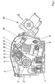
- Fig. 2 and 3 shows the adjustment drive in more detail.
- On the camshaft housing 2 is an approach 30 formed and with a Bore 38 provided in the translational element 19 is performed.
- a base plate 31 attached and opposite by means of a centering 32 positioned this.
- a housing 33 in which the adjustment drive 20 is accommodated is. It has three holes 34 through which it screwed together with the base plate 31 on the neck 30 is.
- It is on one side with a motor flange 35 provided and on its the camshaft housing 2 opposite end with a cover flange 36 on the a lid 37 is attached (removed in Figure 3).
- An electric motor 40 is screwed onto the motor flange 35, its controlled power supply is not shown. Its shaft protrudes into the housing 33 and carries there a worm 41 which is connected to a worm wheel 42 combs. This is by means of the bearings 43 in the base plate 31 and mounted in the housing 33, its hub is a spindle nut 44. Their internal thread acts with a threaded spindle 45 together, firmly with the translational Element 19 connected or part of it. The threaded spindle 45 is limited by a stop collar 46, the stroke of the spindle nut 44 in its end position limited. The threaded spindle 45 sits on the Camshaft end facing away in a threaded extension 47 continues, on which a sleeve 48 by means of a Mother 49 is tightened.
- the sleeve 48 carries a sensor plate 51 on one Friction brake 50 acts to damage the plate 51 to prevent during assembly.
- a guide rod 52 can also be provided.
- the Sensor plate 51 is folded (Fig.2) at its end and forms a shoulder 53 with a position sensor 55 cooperates.
- a HALL sensor that is dimensionally accurate in the Housing 33 is attached and a very accurate response barrier forms what is indicated by the dashed line 56 is.
- a sensor line 57 leads from the sensor path.
- a pulse sensor 58 is provided, which via line 59 is connected. This pulse sensor 58 interacts with the shaft of the electric motor 40.
- the Motor 40 is a very simple controllable electric motor at high speed, which is why it is sufficient to Wave to apply a single brand for pulse generation.
- In this Fig.2 is the adjustment drive 20 in an extreme position, corresponding to the latest possible start of injection.
- Fig.5 and Fig.6 differs from the previous one in that instead of Screw and screw spindle, from the motor - with or without intermediate reduction gear - a pinion 80 is driven, which in a toothing 81 of engages translatory element 19, which of a brake shoe 82 serving as a friction brake its movement is dampened.
- Disc springs 83 force exerted on the element 19 by means of a screw 84 adjustable.
- Means can also be used be provided when driving the electric motor cause the friction shoe to lift off.
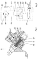
- the adjustment drive 20 is as Drawn box that contains the electric motor 40.
- the Control unit is designated 65, it contains an adjustment control 66 and a target value determination 67.
- Der Adjustment control 66 is via line 57 from the position sensor 55 emitted position signal and over the line 59 counts generated by the pulse sensor fed.
- the setpoint calculator 67 determines from various Input signals 68, e.g. Speed, accelerator pedal position, Engine temperature, a setpoint for the start of injection. This is also the adjustment control unit via a line 69 66 fed. From this is via lines 70 the engine operated controlled.
- the motor assembly is symbolized in FIG. 8 by box 80, staking out the control rod through the box 81.
- the control unit is switched on (box 82), which is the turning of a motor in the vehicle Means that the control unit recognizes that with the control device not subject to the invention that the control rod works together for quantity control is unplugged and triggers the adjustment process.
Landscapes
- Engineering & Computer Science (AREA)
- Mechanical Engineering (AREA)
- General Engineering & Computer Science (AREA)
- Chemical & Material Sciences (AREA)
- Combustion & Propulsion (AREA)
- Fuel-Injection Apparatus (AREA)
- Nozzles (AREA)
- Jet Pumps And Other Pumps (AREA)
- Percussion Or Vibration Massage (AREA)
Description
- Fig.1:
- einen Querschnitt durch die Kopfregion eines Dieselmotors,
- Fig.2:
- vergrößert das Detail A der Fig.1 als erfindungsgemäßer Teil der Verstelleinrichtung in einer Stellung,
- Fig.3:
- Ansicht B zu Fig.2,
- Fig.4:
- wie Fig. 2, jedoch in einer anderen Stellung,
- Fig.5:
- Wie Fig.4, jedoch einer anderen Ausführungsform,
- Fig.6:
- Schnitt nach VI-VI in Fig.5,
- Fig.7:
- Schaltschema der erfindungsgemäßen Einrichtung,
- Fig.8:
- Ablaufdiagramm zum erfindungsgemäßen Verfahren.
Claims (8)
- Spritzverstelleinrichtung für Einspritzpumpendüsen, bestehend aus einem spritzverstellenden Mechanismus (10, 13,17), einem auf diesen einwirkenden Verstellantrieb (20) und einer Steuereinheit (65) für den Verstellantrieb, wobei der Verstellantrieb aus einem translatorischen Element (19), einem elektrischen Stellglied (21) und einem Positionssensor besteht, wobeia) das elektrische Stellglied (21) einen Elektromotor (40) aufweist, der das translatorische Element (19) über ein Getriebe (41,42,44,45; 80,81) verschiebt,b) der Positionssensor(55) bei Passieren des translatorischen Elementes (19) einen Impuls abgibt,c) weiters ein auf Drehung des Motors ansprechender Impulssensor (58) vorgesehen ist, der Zählimpulse abgibt,d) der Positionssensor(55), der Impulssensor(58) und der Elektromotor (40) mit der Steuereinheit (65) in Verbindung stehen, die aus der Ist-Position des spritzverstellenden Mechanismus (10,13,17) und aus einer Soll-Position Stellsignale für den Elektromotor (40) erzeugt,
und wobei weiterse) der Positionssensor (55) ein Schrankensensor ist, der bei Passieren einer mit dem translatorischen Element (19) verbundenen Schulter (53) einen Eichimpuls abgibt,f) die Steuereinheit (65) mit dem Schrankensensors (55) und dem Impulssensor(58) in Verbindung steht und aus den Eichimpulsen und den Zählimpulsen die Ist-Position des spritzverstellenden Mechanismus (10,13,17) ermittelt, undg) dass der Elektromotor (40) über ein Ritzel (81) mit dem translatorischen Element (19) zusammenwirkt für welches eine Reibungsbremse (82) vorgesehen ist. - Spritzverstelleinrichtung nach Anspruch 1, dadurch gekennzeichnet, daß der Schrankensensor (55) ein HALL-Sensor ist und maßgenau in das Gehäuse (33) des Verstellantriebs eingebaut ist.
- Spritzverstelleinrichtung nach Anspruch 2, dadurch gekennzeichnet, daß der Schrankensensor (55) eine Gabelschranke ist und die Schulter (53) von einem Blechplättchen (51) gebildet wird, das in den Schrankensensor (55) eintaucht.
- Verfahren zum Justieren einer Spritzverstelleinrichtung nach einem der vorhergehenden Ansprüche nach Einbau der Pumpendüsen (5) in eine Verbrennungskraftmaschine, dadurch gekennzeichnet, daß das translatorische Element (19) vom Elektromotor (40) des Verstellantriebs (20) angetrieben verfahren und stillgesetzt wird, wenn die Schulter (53) den Schrankensensor (55) durchschreitet und der Zählerstand des Impulszählers in der Steuereinheit (65) in dieser Stellung gleich Null gesetzt wird.
- Verfahren nach Anspruch 4, dadurch gekennzeichnet, daß die Schulter (53) den Schrankensensor (55) zum Justieren immer nur in einer festgelegten Richtung passiert.
- Verfahren nach Anspruch 4, dadurch gekennzeichnet, daß dazu aus dem Status des Schrankensensors (55) entschieden wird, in welcher Richtung das translatorische Element (19) zunächst zu bewegen ist, um den Schrankensensor in der festgelegten Richtung zu passieren, wobei im Falle der Schrankensensor bereits passiert wurde, die Schulter in entgegengesetzter Richtung an diesem vorbeibewegt und dann erst in der festgelegten Richtung durchfahren wird.
- Verfahren nach einem der Ansprüche 4 bis 6, dadurch gekennzeichnet, daß die Justierung vom Steuergerät selbsttätig ausgelöst wird, wenn das mengenbestimmende Glied (9) in der zur Einstellung der Mengenzuordnung eingenommenen Stellung blockiert ist.
- Verfahren nach einem der Ansprüche 4 bis 6, dadurch gekennzeichnet, daß das Steuergerät (65) auch nach der Erstjustierung bei der Montage selbsttätig in definierten Abständen eine Nachjustierung auslöst.
Applications Claiming Priority (2)
| Application Number | Priority Date | Filing Date | Title |
|---|---|---|---|
| DE19517547 | 1995-05-12 | ||
| DE19517547A DE19517547C1 (de) | 1995-05-12 | 1995-05-12 | Spritzverstelleinrichtung für Einspritzpumpendüsen und Verfahren zu deren Justieren |
Publications (3)
| Publication Number | Publication Date |
|---|---|
| EP0742357A2 EP0742357A2 (de) | 1996-11-13 |
| EP0742357A3 EP0742357A3 (de) | 1997-10-29 |
| EP0742357B1 true EP0742357B1 (de) | 2004-12-08 |
Family
ID=7761808
Family Applications (1)
| Application Number | Title | Priority Date | Filing Date |
|---|---|---|---|
| EP96107494A Expired - Lifetime EP0742357B1 (de) | 1995-05-12 | 1996-05-10 | Spritzverstelleinrichtung für Einspritzpumpendüsen und Verfahren zu deren Justieren |
Country Status (3)
| Country | Link |
|---|---|
| EP (1) | EP0742357B1 (de) |
| AT (1) | ATE284484T1 (de) |
| DE (2) | DE19517547C1 (de) |
Families Citing this family (3)
| Publication number | Priority date | Publication date | Assignee | Title |
|---|---|---|---|---|
| RU2268383C1 (ru) * | 2004-07-19 | 2006-01-20 | Открытое акционерное общество "ГАЗ" | Механизм управления углом опережения впрыска топлива |
| US7418933B2 (en) | 2005-04-27 | 2008-09-02 | Honda Motor Co., Ltd. | Variable lift valve operating system for internal combustion engine |
| JP4197028B2 (ja) | 2006-10-31 | 2008-12-17 | 三菱自動車工業株式会社 | 電動アクチュエータの配置構造 |
Family Cites Families (3)
| Publication number | Priority date | Publication date | Assignee | Title |
|---|---|---|---|---|
| FR2417642A1 (fr) * | 1978-02-20 | 1979-09-14 | List Hans | Moteur a injection de carburant, notamment moteur diesel avec installation de reglage de l'instant d'injection |
| AT377581B (de) * | 1981-04-24 | 1985-04-10 | Friedmann & Maier Ag | Einrichtung zum verstellen des einspritzbeginns einer einspritzvorrichtung fuer dieselmotoren |
| US4879985A (en) * | 1985-11-07 | 1989-11-14 | Ail Corporation | Timing and speed sensor for fuel injection pump |
-
1995
- 1995-05-12 DE DE19517547A patent/DE19517547C1/de not_active Expired - Fee Related
-
1996
- 1996-05-10 EP EP96107494A patent/EP0742357B1/de not_active Expired - Lifetime
- 1996-05-10 DE DE1996511158 patent/DE59611158D1/de not_active Expired - Fee Related
- 1996-05-10 AT AT96107494T patent/ATE284484T1/de not_active IP Right Cessation
Also Published As
| Publication number | Publication date |
|---|---|
| DE19517547C1 (de) | 1996-02-29 |
| EP0742357A2 (de) | 1996-11-13 |
| DE59611158D1 (de) | 2005-01-13 |
| ATE284484T1 (de) | 2004-12-15 |
| EP0742357A3 (de) | 1997-10-29 |
Similar Documents
| Publication | Publication Date | Title |
|---|---|---|
| DE3590194C2 (de) | Brennstoff-Einspritzpumpe | |
| DE3907077C2 (de) | ||
| DE60101985T2 (de) | Verfahren zum automatischen Einstellen von Ventilspielen in einem Verbrennungsmotor | |
| DE3619956C2 (de) | ||
| DE3243349A1 (de) | Kraftstoffeinspritzpumpe | |
| DE112006002863T5 (de) | Variabler Ventilmechanismus für eine Brennkraftmaschine | |
| WO1999039114A1 (de) | Exzenterzahnradgetriebe | |
| DE3927043A1 (de) | Lastverstelleinrichtung | |
| DE3143666C2 (de) | ||
| AT395896B (de) | Vorrichtung zum steuern einer einspritzpumpe einer einspritz-brennkraftmaschine | |
| DE3627893C2 (de) | ||
| DE4209586A1 (de) | Drosseleinrichtung | |
| DE2427238A1 (de) | Hydraulischer druckregler fuer nichtblockierende bremsanlagen | |
| EP0359990B1 (de) | Vorrichtung mit einem Stellmotor zum Eingriff in eine Übertragungseinrichtung | |
| DE4006303C2 (de) | ||
| DE19517547C1 (de) | Spritzverstelleinrichtung für Einspritzpumpendüsen und Verfahren zu deren Justieren | |
| DE4443783A1 (de) | Schaltvorrichtung für eine Klauenkupplung und Verfahren zu deren Einstellung | |
| WO2006117080A1 (de) | Verstellvorrichtung für eine brennkraftmaschine | |
| DE3224951C2 (de) | ||
| DE19612397A1 (de) | Stellvorrichtung zur relativen Winkelverstellung einer angetriebenen Welle, insbesondere Nockenwelle einer Brennkraftmaschine | |
| DE3625600A1 (de) | Servolenkanlage | |
| DE3322214C2 (de) | ||
| DE3728672A1 (de) | Farbkastenvorrichtung fuer eine druckmaschine | |
| DE4033802A1 (de) | Lastverstelleinrichtung | |
| DE69508900T2 (de) | Pedalbetätigungsvorrichtung zur Steuerung des Bowdenzugs der Drosselklappe einer Brennstoffzufuhrvorrichtung für Brennkraftmaschine |
Legal Events
| Date | Code | Title | Description |
|---|---|---|---|
| PUAI | Public reference made under article 153(3) epc to a published international application that has entered the european phase |
Free format text: ORIGINAL CODE: 0009012 |
|
| AK | Designated contracting states |
Kind code of ref document: A2 Designated state(s): AT DE FR GB |
|
| PUAL | Search report despatched |
Free format text: ORIGINAL CODE: 0009013 |
|
| AK | Designated contracting states |
Kind code of ref document: A3 Designated state(s): AT DE FR GB |
|
| 17P | Request for examination filed |
Effective date: 19980428 |
|
| 17Q | First examination report despatched |
Effective date: 20030829 |
|
| GRAP | Despatch of communication of intention to grant a patent |
Free format text: ORIGINAL CODE: EPIDOSNIGR1 |
|
| RAP1 | Party data changed (applicant data changed or rights of an application transferred) |
Owner name: ENGINEERING CENTER STEYR GMBH & CO KG |
|
| GRAS | Grant fee paid |
Free format text: ORIGINAL CODE: EPIDOSNIGR3 |
|
| GRAA | (expected) grant |
Free format text: ORIGINAL CODE: 0009210 |
|
| RIN1 | Information on inventor provided before grant (corrected) |
Inventor name: SCHMIDT, HARALD, ING. Inventor name: MORELL, JOSEF Inventor name: KRENN, ANDREAS, ING. MAG. Inventor name: HACK, WALTER |
|
| AK | Designated contracting states |
Kind code of ref document: B1 Designated state(s): AT DE FR GB |
|
| PG25 | Lapsed in a contracting state [announced via postgrant information from national office to epo] |
Ref country code: FR Free format text: LAPSE BECAUSE OF NON-PAYMENT OF DUE FEES Effective date: 20041208 |
|
| REG | Reference to a national code |
Ref country code: GB Ref legal event code: FG4D Free format text: NOT ENGLISH |
|
| REF | Corresponds to: |
Ref document number: 59611158 Country of ref document: DE Date of ref document: 20050113 Kind code of ref document: P |
|
| GBT | Gb: translation of ep patent filed (gb section 77(6)(a)/1977) |
Effective date: 20050308 |
|
| PG25 | Lapsed in a contracting state [announced via postgrant information from national office to epo] |
Ref country code: GB Free format text: LAPSE BECAUSE OF NON-PAYMENT OF DUE FEES Effective date: 20050510 Ref country code: AT Free format text: LAPSE BECAUSE OF NON-PAYMENT OF DUE FEES Effective date: 20050510 |
|
| PLBE | No opposition filed within time limit |
Free format text: ORIGINAL CODE: 0009261 |
|
| STAA | Information on the status of an ep patent application or granted ep patent |
Free format text: STATUS: NO OPPOSITION FILED WITHIN TIME LIMIT |
|
| 26N | No opposition filed |
Effective date: 20050909 |
|
| PG25 | Lapsed in a contracting state [announced via postgrant information from national office to epo] |
Ref country code: DE Free format text: LAPSE BECAUSE OF NON-PAYMENT OF DUE FEES Effective date: 20051201 |
|
| GBPC | Gb: european patent ceased through non-payment of renewal fee |
Effective date: 20050510 |
|
| EN | Fr: translation not filed |