EP0740973B1 - Machine a décolleter les tubes et procédé de tronçonnage de pièces tubulaires à partir de tube - Google Patents
Machine a décolleter les tubes et procédé de tronçonnage de pièces tubulaires à partir de tube Download PDFInfo
- Publication number
- EP0740973B1 EP0740973B1 EP96106251A EP96106251A EP0740973B1 EP 0740973 B1 EP0740973 B1 EP 0740973B1 EP 96106251 A EP96106251 A EP 96106251A EP 96106251 A EP96106251 A EP 96106251A EP 0740973 B1 EP0740973 B1 EP 0740973B1
- Authority
- EP
- European Patent Office
- Prior art keywords
- pipe
- cutting
- head
- clamping
- machine
- Prior art date
- Legal status (The legal status is an assumption and is not a legal conclusion. Google has not performed a legal analysis and makes no representation as to the accuracy of the status listed.)
- Expired - Lifetime
Links
Images

Classifications
-
- B—PERFORMING OPERATIONS; TRANSPORTING
- B23—MACHINE TOOLS; METAL-WORKING NOT OTHERWISE PROVIDED FOR
- B23D—PLANING; SLOTTING; SHEARING; BROACHING; SAWING; FILING; SCRAPING; LIKE OPERATIONS FOR WORKING METAL BY REMOVING MATERIAL, NOT OTHERWISE PROVIDED FOR
- B23D21/00—Machines or devices for shearing or cutting tubes
- B23D21/04—Tube-severing machines with rotating tool-carrier
-
- B—PERFORMING OPERATIONS; TRANSPORTING
- B23—MACHINE TOOLS; METAL-WORKING NOT OTHERWISE PROVIDED FOR
- B23B—TURNING; BORING
- B23B5/00—Turning-machines or devices specially adapted for particular work; Accessories specially adapted therefor
- B23B5/14—Cutting-off lathes
-
- Y—GENERAL TAGGING OF NEW TECHNOLOGICAL DEVELOPMENTS; GENERAL TAGGING OF CROSS-SECTIONAL TECHNOLOGIES SPANNING OVER SEVERAL SECTIONS OF THE IPC; TECHNICAL SUBJECTS COVERED BY FORMER USPC CROSS-REFERENCE ART COLLECTIONS [XRACs] AND DIGESTS
- Y10—TECHNICAL SUBJECTS COVERED BY FORMER USPC
- Y10T—TECHNICAL SUBJECTS COVERED BY FORMER US CLASSIFICATION
- Y10T82/00—Turning
- Y10T82/16—Severing or cut-off
- Y10T82/16016—Processes
-
- Y—GENERAL TAGGING OF NEW TECHNOLOGICAL DEVELOPMENTS; GENERAL TAGGING OF CROSS-SECTIONAL TECHNOLOGIES SPANNING OVER SEVERAL SECTIONS OF THE IPC; TECHNICAL SUBJECTS COVERED BY FORMER USPC CROSS-REFERENCE ART COLLECTIONS [XRACs] AND DIGESTS
- Y10—TECHNICAL SUBJECTS COVERED BY FORMER USPC
- Y10T—TECHNICAL SUBJECTS COVERED BY FORMER US CLASSIFICATION
- Y10T82/00—Turning
- Y10T82/16—Severing or cut-off
- Y10T82/16032—Automatic and/or triggered control
-
- Y—GENERAL TAGGING OF NEW TECHNOLOGICAL DEVELOPMENTS; GENERAL TAGGING OF CROSS-SECTIONAL TECHNOLOGIES SPANNING OVER SEVERAL SECTIONS OF THE IPC; TECHNICAL SUBJECTS COVERED BY FORMER USPC CROSS-REFERENCE ART COLLECTIONS [XRACs] AND DIGESTS
- Y10—TECHNICAL SUBJECTS COVERED BY FORMER USPC
- Y10T—TECHNICAL SUBJECTS COVERED BY FORMER US CLASSIFICATION
- Y10T82/00—Turning
- Y10T82/16—Severing or cut-off
- Y10T82/16426—Infeed means
- Y10T82/16442—Infeed means with means to circumrotate tool[s] about work
-
- Y—GENERAL TAGGING OF NEW TECHNOLOGICAL DEVELOPMENTS; GENERAL TAGGING OF CROSS-SECTIONAL TECHNOLOGIES SPANNING OVER SEVERAL SECTIONS OF THE IPC; TECHNICAL SUBJECTS COVERED BY FORMER USPC CROSS-REFERENCE ART COLLECTIONS [XRACs] AND DIGESTS
- Y10—TECHNICAL SUBJECTS COVERED BY FORMER USPC
- Y10T—TECHNICAL SUBJECTS COVERED BY FORMER US CLASSIFICATION
- Y10T82/00—Turning
- Y10T82/22—Portable lathe for pipe turning
Definitions
- the invention relates to a pipe cutting machine and a Process for parting pipe pieces from a pipe, especially for parting off ball bearing rings from thick-walled ones Pipes.
- Pipe parting machines of this type have a parting head Clamping jaws for external clamping of a pipe end, a rotatable one Face plate for receiving at least one radially deliverable parting tool and possibly at least one radial deliverable chamfering tool and often a pick-off for Grasp and put down a cut piece of pipe.
- a such pipe cutting machine is in European Patent No. 0 425 994 by the same applicant.
- the pipe to be cut is opened support rollers arranged in alignment with the parting head, from which is driven at least one.
- the pipe is supported by the parting head and the support roller Face plate through to an adjustable stop transported and then clamped using the jaws, after which the parting off process is carried out.
- the attack must be very powerful because the stop is not just that Position the pipe end, but also the feed of the pipe must stop, especially with thick-walled pipes their large mass considerable forces occur.
- the pipe must stop from the area of the Tube end are moved away to the pipe piece to be cut off to be able to grab and store using a claw. That I this process repeated with each feed step dead times for the machine that is applying the spread cut pieces of pipe reduced. Furthermore you can Inaccuracies in the width of the cut piece of pipe occur when z. B. a chip between the stop and the pipe end.
- the feed by means of a driven support roller is indeed structurally relatively simple, but does not allow the Adjust feed to an exact value, rather that The end of the pipe was always pushed against the stop become. Due to the free space wear on the Parting tool gradually widened cut pieces of pipe, which can only be corrected if a corresponding setting option for the stop, preferably created via an additional CNC axis.
- Ball bearing rings are pronounced Bulk products that are as fully automated as possible with the largest Machine utilization and the lowest possible machining losses with the expensive, high-alloy tubular steels and if possible low wear of expensive tools can be cut off should.
- Small cutting losses result from the Sawing off the ball bearing rings using band saws, as this Cutting width is at most 2 mm.
- the cutting speed of saws is not high and the service life of the Saw bands are low because a band saw is generally only across can saw through a pipe all the way on the hard zones in the area of the outside diameter and the Inside diameter meets. Add to that the cut cannot be exactly perpendicular to the pipe axis, because that Dodge elastic band that is not guided in the area of the pipe can, so that planning the tapped ball bearing rings as additional work is always required.
- the invention is based on the problem of a method for Parting off pipe pieces from a pipe with a hard zone at least in the area of the outer diameter, in particular for Parting off ball bearing rings from thick-walled tubes as well to create a pipe cutting machine with which pieces of pipe with high machine utilization, low machining as well as possibly accurate, quick and accurate without using a stop perpendicular to the pipe axis with little tool wear cut off.
- the Cutting speed will increase significantly, and it will each parting off a completely flat, exactly perpendicular to the Pipe axis extending ring surface created which, in contrast to Sawing off does not require any subsequent planning. Parting off can be done with a tool that is no wider needs to be as a saw band, so that compared to conventional Parting process less of the expensive material is machined.
- This hard zone can be precisely and without running the Parting tool and without special wear of the Pierce the parting tool, so that the costs Tool wear can be significantly reduced. Because if that hard zone with low feed and / or less Cutting speed is pierced, the increases Life of the parting tool, so that the parting tool can be made narrower and therefore less expensive material is machined.
- the parting tool holder has to be large Wall thickness of the pipes a large collar length of the narrow Have insert-bearing area, which is naturally a has low rigidity in the direction of the tube axis, however can be emigrated by slowly piercing the avoid hard zone.
- the slow piercing of the hard zone therefore not only serves to reduce wear on the parting tool but also a precise, non-proceeding starting point for the Parting process.
- the further measuring the cutting force during parting off be made to the cut piece of pipe by means of a Remove the tapping device as soon as the cutting force is below a predeterminable value drops.
- This procedure is based on the consideration that one Stop can be dispensed with and the associated disadvantages Avoid if the pipe end clamped in the parting head is detected in terms of its location and the slip-free working feed unit is then controlled so that the pipe for the parting process exactly the width of the pipe section to be cut off plus the width of the Parting tool transported through the parting head, after which that Pipe clamped again and a piece of pipe with the given Width is cut off.
- Insert and ancestor a new pipe a defined one
- the beginning of the pipe is determined by a short Plan processing step is subjected. This will Impurities on the pipe end, such as not straight or not end faces at right angles to the pipe axis are leveled and created a reference plane, which as Starting point for the CNC-controlled feed by the width of the Corresponding paths to be cut off is used.
- the wear of the for face machining of the tube face and Parting off the pipe pieces used can be done by take the feed control into account without further ado. This can either done by the width of the cut Pipe pieces are measured and the feed is corrected if into the control unit a result of empirical values Correction value is entered, which is an automatic adjustment of the feed causes.
- the pipe advantageously after parting off and possibly chamfering the Piece of pipe and after opening the jaws of the parting head withdrawn a short distance by means of the feed unit the parting tool and possibly the chamfering tool, without the To touch the tube face, be withdrawn and the Feed path for parting off and chamfering another if necessary Pipe section around the path section can be enlarged when retracting.
- the further a pipe parting machine with a parting head Clamping jaws for external clamping of a pipe end, a rotatable one Face plate for receiving at least one radially adjustable Parting tool for parting with switchable feed and / or Cutting speed and possibly at least one radial adjustable chamfering tool and one slip-free on the tube attacking, starting from the pipe end clamped in the parting head adjustable to predefinable widths of the pipe pieces to be cut off Feed unit suggested.
- a CNC-controlled feed unit can advantageously be used use as this way without any special effort Have feed steps controlled with high accuracy.
- Pipe end responsive sensing device may be provided.
- About the Control can then set a required feed, who takes the probe as a starting point and causes that the pipe through the parting head and the face plate such a route is transported that in the area of Parting tool is a pipe piece to be cut off, that exactly has the required width.
- the slip-free feed unit can be the tube from one driven roller pair, belt pair or encompassing on both sides Pair of chains exist, the surface of which is such that a slip-free feed is guaranteed.
- the feed unit can preferably be equipped with clamping jaws Internal clamping of the pipe end to be provided in the for Engage cut-off head opposite pipe end.
- This one Feed unit attacks with its jaws on the pipe end so that an absolutely slip-free drive ensures that the
- the advantage is that the tube is up to by means of the feed unit can be transported far into the parting head, so that Remnants only remain with a length that the axial Extension of the clamping jaws in the parting head or the clamping jaws correspond to the feed unit.
- the Feed unit an at least height adjustable, preferably Bracket adjustable and lockable on all sides to provide the jaws.
- the feed unit can have a carriage that the Bracket for the jaws and one on longitudinal guides Machine bed can be arranged displaceably.
- These support rollers can advantageously be adjusted in height be to the pipe lying in the support rollers with respect to the set the pipe axis corresponding to the actual pipe outside diameter to be able to.
- the actual outside diameter can also be determined using a Position sensor on a clamping device on a wiper for the Determine the pipe piece that has been cut.
- the actual outside diameter of the pipe is on this or on determined in another way, the parting tool can be in rapid traverse lead very close to the outer surface of the pipe so that this further increases the dead time of the pipe cutting machine can be reduced.
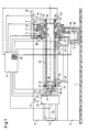
- a machine bed 2 is one Pipe cutting machine built.
- This machine bed 2 has a side guide rail support 3 with parallel Guide rails 4 on.
- the length of the machine bed 2 is on the length of the pipes to be cut adapted from 3 m to Can go 10 m.
- a parting head 5 is located at one end of the machine bed 2 arranged, which is shown here only schematically.
- a face plate 8 To the Parting head 5 is a face plate 8 by means of roller bearings 9 rotatably mounted.
- the exact structure of the parting head 5 with the Face plate 8 can be found in European patent 0 425 994 from the same applicant.
- the parting head 5 has an annular piston 6 with inclined surfaces that can be moved pneumatically or hydraulically and thereby with corresponding inclined surfaces on clamping jaws 7 cooperates in this way radially against the outer circumference a tube 33 can be tensioned.
- a Ring piston 6 connected transducer 43 can be the axial Position of the annular piston after tensioning a tube 33 and thus determine the actual outside diameter of the tube 33.
- transducer 43 on the parting head 6 can also a displacement transducer 45 on a tensioning device on the wiper 19 in use the same way. It is also possible to To determine the actual outside diameter of a pipe 33 before using it its front end is pushed through the parting head 5. This can be arranged on the machine bed 2 Use a laser measuring device that measures the actual outside diameter around the path offset up to the parting area and the measured values to a CNC control 41 for the pipe cutting machine transmitted.
- Radial guides 10 are arranged on the face plate 8 which slide 11 with a parting tool 12 and Allow chamfering tool 13 to be adjusted radially.
- the faceplate 8 has an external toothing 14 which is connected via an intermediate wheel 15 and a pinion 16 is coupled to a drive motor 17 and in this way set in rotation by the drive motor 17 becomes.
- a wiper 19 is displaceable on a carrier 18 arranged, which serves to cut a pipe piece 34 grab and put down.
- a drivable spindle 20 mounted to move a Feed unit 21 is used along the guide rails 4.
- the feed unit 21 consists of a carriage 22 of the by means of guides 33 which the guide rails 4th reach behind, slidably mounted on the guide rail support 3 is.
- a drive motor 24 attached to the carriage 22 displaces one Spindle 25 in rotation, by means of which a holder 26 for a bushing 27 can be adjusted in height.
- a piston 28 which is arranged over a Drawbar 29 is connected to a cone 30.
- This Cone 30 acts with its inclined surfaces on corresponding Inclined surfaces of jaws 31, which are in this way have it adjusted radially and for internal clamping of the tube 33 serve.
- Displacement sensor 44 allows the axial position of the annular piston to be reduced the tensioning of a tube 33 and thus the actual inside diameter determine the tube 33.
- the Feed unit 21 moved to the extreme left position. Then the stop 40 is briefly lowered so that a Tube 33 'can roll on support rollers 36. The next pipe 33 'is then immediately again by the stop 40th captured.
- the support rollers 36 are held by support rods 37 which in Guides on the machine bed 2 are held adjustable in height.
- control unit 41 which is preferably a Contains CNC control of the parting machine
- the Support rollers 36 depending on the outer diameter of the tube 33 in adjust the height so that the actual outside diameter of the Tube 33 related axis of the tube exactly in the axis of Parting head 5 and the face plate 8 comes to rest.
- Control unit 41 also set exactly in height, whereby however, this height adjustment is carried out in such a way that existing ovalities and eccentricities of the inner diameter of the tube 33 compared to the outer diameter be that related to the outside diameter Axis position when clamping the jaws 31 of the feed unit 21 not changed.
- the clamping bush 27 settles when clamping the jaws 31 on the end face of the tube 33 so that a defined position of the pipe end with respect to the Feed unit 21 results. From the position sensor 44 recorded axial position of the piston 28, which is a measure of the is radial expansion of the jaws 31, can directly derive the actual inside diameter of the tube 33 and enter into the control unit 41.
- the tube 33 on Clamping device 46 arranged outside diameter can be arranged the bracket 26 on the carriage 22 freely in all directions be movable and is only after the clamping jaws 31 found so that easy centering in this way of the actual outer diameter of the tube 33 with reference to the Parting machine axis is carried out.
- the tube 33 is moved by means of the feed unit 21 rotation of the spindle 20 caused by the control unit 41 in the direction of the parting head 5 with the face plate 8 postponed.
- a signal reaches the control unit 41 as soon as the Pipe face 35 reaches the area of the feeler 38. Since this probe 38 has a fixed, the Control device 41 entered distance to parting tool 12th has, the tube 33 is now by means of the feed unit 21 so far through the parting head 5 and the face plate 8 passed through that the tube end face 35 in the area of Parting tool 12 with a slight addition, whereupon, controlled by the control unit 41, the jaws 7 clamped against the outer tube surface by means of the annular piston 6 become.
- the displacement sensor 43 axial position of the annular piston 6 directly Actual outside diameter of the tube 6.
- a defined pipe start that is precisely defined in its position is determined in that the tube end face 35 by means of Parting tool 12 is subjected to a plan machining operation, with which impurities are removed and exactly Make the face 35 at right angles to the pipe axis to let.
- the gripper 19 takes the pipe piece 34 to be cut off, the Tools 12, 13 are turned during the rotation of the face plate 8 first delivered in rapid traverse until they hit the outer tube surface almost touch, after which the tools 12, 13 with reduced Feed and / or reduced cutting speed against the Outer tube surface and a hard zone in the Area of the pipe outer diameter, e.g. B. a scale Roll skin, a hard cast skin or one hard when cooling pierce the zone. After piercing this hard one The feed and / or the cutting speed become the zone increased by one piece of pipe as far as the pipe material allows to cut off with the highest possible machining performance.
- the axial movement of the tap can be advantageously to save non-productive times, with a signal from a Cutting force measuring device, which determines when the Machining is finished, start.
- the tools 12, 13 can now be radially into the Move back to the starting position, however, due to the Material elasticities the risk that the tools 12, 13 die Touch the end face of the tube 33, thereby wearing and one Insert spiral groove.
- the tube 33 after parting and possibly chamfering the pipe section 34 and after opening the jaws 6 of the parting head 5 by means of Feed unit 21 can be withdrawn a short distance, after which the tools 12, 13 without the pipe end face touch, be withdrawn.
- the control unit 41 then again issues a command to the Feed unit 21, the tube 33 around the entered path plus the distance that tube 33 was retracted, drive forward, again to cut a piece of pipe 34.
- control unit 41 on the basis of To program empirical values, d. H. after tapping a predefinable number of pipe sections 34 is automatically Corrected feed path by the required amount.
- the clamping bush 27 and the carrier 26 have a diameter having a maximum equal to the outer diameter of the tube 33 and the length of the clamping bush 27 and the holder 26 is sufficient to extend the tube 33 into the area of the clamping jaws 7 to push in the parting head 5, the tube 33 can be except for one Cut the short remaining piece into the pipe pieces 34.
- the support rollers 36 can not only serve to close the tube 33 hold when a new tube 33 is inserted into the parting machine becomes. Especially with very long pipes, the maximum length of which can be up to 10 m, it is advantageous to the tube 33 in Area between the feed unit 21 and the parting head 5 to support a deflection that is inclined Pipe end would have to be avoided.
- the support rollers 36 must be lowered at the moment when the carriage 22 reaches the area of a support roller 36. This can also be done by means of the control unit 41 do it automatically. It is also possible to Carriage 22 to design the feed unit 21 so that it is on its path does not collide with the support rollers 36.
- the feed device 21 shown at the end of the tube 33 attacks represents a preferred embodiment
- the invention also extends to non-slip Feed units that are directly adjacent to the parting head 5 attack the pipe 33 if it is ensured that a control such feed unit by the control unit 41 lets that always set the feed path to Parting off pipe pieces 34 of predetermined width and within the specified tolerances are covered without Area of the face plate 8 or the tapper 19 arranged Stops are required.
- measuring the actual outside diameter and Actual inside diameter of the tube can be different than by measuring the displacement of the pistons 6, 28, e.g. B. by non-contact sensors. Are not major ones Tolerances for the outside and inside pipe diameters expect, it may be enough the nominal outside diameter and the Nominal inside diameter via the keyboard 42 into the controller 41 to enter.
Claims (20)
- Procédé pour tronçonner et éventuellement chanfreiner des morceaux de tube à partir d'un tube présentant une zone dure au moins au voisinage du diamètre extérieur, notamment de tubes à paroi épaisse pour réaliser des bagues de roulement à billes, comportant les étapes suivantes:mesure du diamètre extérieur réel du tube au voisinage du point de tronçonnage sur le tube ou introduction du diamètre extérieur nominal du tube,approche d'un outil de tronçonnage vers la surface extérieure du tube, à grande vitesse,commutation de l'avance et/ou de la vitesse de coupe sur une valeur réduite pour percer la zone dure,commutation de l'avance et/ou de la vitesse de coupe sur une vitesse de travail adaptée à la matière du tube pour le tronçonnage rapide d'une bague.
- Procédé selon la revendication 1, comportant les étapes supplémentaires suivantes:mesure du diamètre intérieur réel du tube ou introduction du diamètre intérieur nominal du tube,commutation de l'avance et/ou de la vitesse de coupe sur une valeur plus basse à l'approche du diamètre intérieur pour le tronçonnage complet du morceau de tube avec formation réduite de bavures et avec sectionnement complet d'un copeau annulaire mince et propre, ainsi qu'avec une usure réduite de l'outil en présence d'une zone dure au voisinage du diamètre intérieur.
- Procédé selon la revendication 1 ou 2, comportant les étapes supplémentaires suivantes:mesure de la force de coupe pendant le tronçonnage,évacuation du morceau de tube tronçonné au moyen d'un dispositif de préhension et d'enlèvement, dès que la force de coupe passe au-dessous d'une valeur prédéterminée.
- Procédé de tronçonnage de morceaux de tube, notamment selon une ou plusieurs des revendications 1 à 3, comportant les étapes suivantes:mise en place d'un tube dans une machine à tronçonner les tubes,saisie du tube par une unité d'avance sans glissement,avance du tube au moyen de l'unité d'avance,détection du passage de l'extrémité du tube avant son introduction dans une tête de tronçonnage munie de mâchoires de serrage, au moyen d'une unité de palpage,avance du tube à travers la tête de tronçonnage sur une distance réglable et serrage des mâchoires de serrage,dressage de la face frontale du tube, ressortant de la tête de tronçonnage, pour fixer une amorce de tube définie,avance à commande numérique du tube sur une longueur sélectionnable du morceau de tube à tronçonner, en partant de l'amorce de tube définie,tronçonnage et éventuellement chanfreinage du morceau de tube avec une vitesse d'avance et/ou de coupe commutable etrépétition de l'avance et du tronçonnage.
- Procédé selon la revendication 4, caractérisé en ce que l'usure de l'outil utilisé pour le dressage de la face frontale du tube et pour le tronçonnage des morceaux de tube est prise en compte par la commande d'avance.
- Procédé selon la revendication 4 ou 5, caractérisé en ce que le tube est avancé pas à pas au moyen d'une unité d'avance, agissant sur l'extrémité du tube et comportant des mâchoires de serrage pour serrage intérieur, jusqu'à ce qu'il ne reste plus dans la tête de tronçonnage qu'un morceau résiduel correspondant à la longueur de serrage nécessaire, le morceau résiduel est retiré de la tête de tronçonnage au moyen de l'unité d'avance et le morceau résiduel retiré est enlevé.
- Procédé selon la revendication 4, 5 ou 6, caractérisé en ce qu'après tronçonnage et éventuellement chanfreinage du morceau de tube et après ouverture des mâchoires de serrage de la tête de tronçonnage, le tube est reculé au moyen de l'unité d'avance, sur une courte distance, l'outil de tronçonnage et éventuellement l'outil de chanfreinage sont retirés, sans contact avec la face frontale du tube, et la course d'avance pour le tronçonnage et éventuellement le chanfreinage d'un autre morceau de tube est augmentée de la distance du recul.
- Procédé selon la revendication 4, 5, 6 ou 7, caractérisé en ce que l'accélération et la vitesse de l'avance du tube sont commandées en fonction de la masse du tube concerné.
- Machine pour tronçonner les tubes, notamment pour la mise en oeuvre du procédé selon une ou plusieurs des revendications 1 à 8, comportantune tête de tronçonnage (5) avec mâchoires de serrage (7) pour le serrage extérieur de l'extrémité d'un tube,un disque de dressage rotatif (8) destiné à recevoir au moins un outil de tronçonnage (12) ajustable radialement pour le tronçonnage avec vitesse commutable d'avance et/ou de coupe, et éventuellement au moins un outil de chanfreinage (13) ajustable radialement etune unité d'avance (21) agissant sans glissement sur le tube, réglable sur des longueurs prédéterminées des morceaux de tube (34) à tronçonner, en partant de l'extrémité du tube serrée dans la tête de tronçonnage (5).
- Machine pour tronçonner les tubes selon la revendication 9, caractérisée par une unité d'avance (21) à commande numérique.
- Machine pour tronçonner les tubes selon la revendication 10, caractérisée par un dispositif de palpage (38) disposé à une distance prédéterminée, dans le sens d'avance, devant la tête de tronçonnage (5), et réagissant au passage de l'extrémité du tube à serrer dans la tête de tronçonnage (5).
- Machine pour tronçonner les tubes selon une ou plusieurs des revendications 9 à 11, caractérisée par une unité d'avance (21) avec mâchoires de serrage (31) pour le serrage intérieur de l'extrémité du tube.
- Machine pour tronçonner les tubes selon la revendication 12, caractérisée par un support (26) pour les mâchoires de serrage (31), qui est au moins réglable en hauteur, de préférence réglable de tous côtés, et qui peut être bloqué sur l'unité d'avance (21).
- Machine pour tronçonner les tubes selon la revendication 13, caractérisée par un dispositif de serrage (46) serrant de manière centrée par rapport au centre de la machine à tronçonner, qui est situé au voisinage de l'extrémité arrière du tube et qui centre le diamètre extérieur du tube par rapport au centre de la machine à tronçonner, de sorte que le support (26) à bloquer peut s'adapter dans tous les sens à un diamètre extérieur du tube éventuellement excentré.
- Machine pour tronçonner les tubes selon une ou plusieurs des revendications 9 à 14, caractérisée par un banc de machine (2) comportant des organes de guidage longitudinaux (4) et un dispositif d'entraínement (20) pour le support (26) des mâchoires de serrage (31), lequel support est déplaçable sur les organes de guidage (4) au moyen d'un chariot (22), ainsi qu'au moins un rouleau d'appui (36) pour le tube (33), disposé sur le banc de machine (2).
- Machine pour tronçonner les tubes selon la revendication 15, caractérisée en ce que le (les) rouleau(x) d'appui (36) est (sont) réglable(s) en hauteur en vue d'aligner l'axe du tube (33) qui se trouve dans les rouleaux d'appui (26), en rapport avec le diamètre extérieur réel mesuré sur l'axe de la tête à tronçonner (5).
- Machine pour tronçonner les tubes selon une ou plusieurs des revendications 9 à 16, caractérisée par une tête de tronçonnage (5) comportant un piston de serrage (6) pouvant coulisser axialement et serrant radialement les mâchoires de serrage (7), ainsi qu'un capteur de course (43), accouplé au piston de serrage (6), pour déterminer le diamètre extérieur réel du tube (33) à partir de la course du piston de serrage (6).
- Machine pour tronçonner les tubes selon une ou plusieurs des revendications 9 à 16, caractérisée par un capteur de course (45) sur un dispositif de serrage situé sur un dispositif de préhension et d'enlèvement (19) pour la mesure du diamètre extérieur réel du tube (33).
- Machine pour tronçonner les tubes selon une ou plusieurs des revendications 9 à 18, caractérisée par une unité d'avance (21) comportant un piston de serrage (28) pouvant coulisser axialement et serrant radialement les mâchoires de serrage (31), ainsi qu'un capteur de course (44) accouplé au piston de serrage (28) pour déterminer le diamètre intérieur réel du tube (33) à partir de la course du piston de serrage (6).
- Machine pour tronçonner les tubes selon une ou plusieurs des revendications 9 à 16, caractérisée par un appareil de mesure de diamètre disposé devant la tête de tronçonnage (5), de préférence un appareil de mesure à laser, qui mesure le diamètre extérieur réel, décalé de la distance par rapport à la zone de tronçonnage, et le transmet à l'unité de commande (41) de la machine à tronçonner.
Applications Claiming Priority (4)
| Application Number | Priority Date | Filing Date | Title |
|---|---|---|---|
| DE19516035 | 1995-05-04 | ||
| DE19516035 | 1995-05-04 | ||
| DE19613500 | 1996-04-04 | ||
| DE19613500A DE19613500A1 (de) | 1995-05-04 | 1996-04-04 | Rohrabstechmaschine und Verfahren zum Abstechen von Rohrstücken von einem Rohr |
Publications (3)
| Publication Number | Publication Date |
|---|---|
| EP0740973A2 EP0740973A2 (fr) | 1996-11-06 |
| EP0740973A3 EP0740973A3 (fr) | 1997-04-16 |
| EP0740973B1 true EP0740973B1 (fr) | 2000-07-19 |
Family
ID=26014796
Family Applications (1)
| Application Number | Title | Priority Date | Filing Date |
|---|---|---|---|
| EP96106251A Expired - Lifetime EP0740973B1 (fr) | 1995-05-04 | 1996-04-20 | Machine a décolleter les tubes et procédé de tronçonnage de pièces tubulaires à partir de tube |
Country Status (2)
| Country | Link |
|---|---|
| US (1) | US5894771A (fr) |
| EP (1) | EP0740973B1 (fr) |
Cited By (1)
| Publication number | Priority date | Publication date | Assignee | Title |
|---|---|---|---|---|
| NL1038140C2 (nl) * | 2010-07-30 | 2012-01-31 | Workum Beheer B V Van | Inrichting voor het afsnijden van een pijp en/of het bewerken van een eind van een pijp, beitelkop. |
Families Citing this family (32)
| Publication number | Priority date | Publication date | Assignee | Title |
|---|---|---|---|---|
| DE19734563C1 (de) * | 1997-08-04 | 1998-12-03 | Mannesmann Ag | Verfahren zur Herstellung von Wälzlagerringen aus Stahl |
| DE19807337A1 (de) * | 1998-02-20 | 1999-09-02 | Ulmer | Verfahren zum Schneiden von Wellrohren sowie Vorrichtung zur Durchführung des Verfahrens |
| US6079303A (en) * | 1998-04-03 | 2000-06-27 | N. T. Naum Technologies Ltd. | Automatic adjustable power chuck system and method |
| FI111345B (fi) * | 1999-04-19 | 2003-07-15 | T Drill Oy | Järjestelmä putken tai tangon katkaisukoneen katkaisutyökalujen esiase ttelemiseksi |
| US6601650B2 (en) * | 2001-08-09 | 2003-08-05 | Worldwide Oilfield Machine, Inc. | Method and apparatus for replacing BOP with gate valve |
| US6609533B2 (en) | 2001-03-08 | 2003-08-26 | World Wide Oilfield Machine, Inc. | Valve actuator and method |
| US8714263B2 (en) | 2001-03-08 | 2014-05-06 | Worldwide Oilfield Machine, Inc. | Lightweight and compact subsea intervention package and method |
| US7578349B2 (en) * | 2001-03-08 | 2009-08-25 | Worldwide Oilfield Machine, Inc. | Lightweight and compact subsea intervention package and method |
| US6557227B2 (en) * | 2001-07-09 | 2003-05-06 | Nan Ya Plastics Corporation | Hard pipe cutting equipment |
| DE10143387B4 (de) * | 2001-09-04 | 2010-07-29 | Komet Group Gmbh | Werkzeugkopf für den Einsatz in Werkzeugmaschinen |
| US7398716B2 (en) * | 2003-02-20 | 2008-07-15 | John Quigley | Method and apparatus for processing a tube |
| FI119419B2 (fi) | 2005-01-26 | 2011-10-13 | Raumaster Paper Oy | Menetelmä ja laitteisto hylsyn katkaisemiseksi |
| US8091455B2 (en) | 2008-01-30 | 2012-01-10 | Cummins Filtration Ip, Inc. | Apparatus, system, and method for cutting tubes |
| US8082823B2 (en) * | 2008-10-22 | 2011-12-27 | Kravitch Nick C | Scraping tool |
| US8806996B2 (en) * | 2009-12-02 | 2014-08-19 | The Fiber Resource Group, Inc. | System and method of an automated roll sizing machine |
| NL1038144C2 (nl) * | 2010-07-30 | 2012-01-31 | Workum Beheer B V Van | Inrichting voor het afsnijden van een pijp en/of het bewerken van een eind van een pijp, beitelkop. |
| CN102151841B (zh) * | 2010-12-31 | 2015-09-30 | 广东新志密封技术有限公司 | 一种聚四氟乙烯导向带倒角的方法及倒角机 |
| AT511195B1 (de) * | 2011-01-28 | 2012-10-15 | Wfl Millturn Tech Gmbh & Co Kg | Verfahren zur verringerung der exzentrizität der innen- zur aussenfläche |
| CN102773562A (zh) * | 2011-05-13 | 2012-11-14 | 温天然 | 圆杆状物料的一体式裁切暨倒角装置及其加工方法 |
| JP2013022694A (ja) * | 2011-07-22 | 2013-02-04 | Sankyo Shigyo Kk | パイプ切断装置 |
| ITPI20110084A1 (it) * | 2011-07-23 | 2013-01-24 | Ga Vo Meccanica S N C | Apparecchiatura per tagliare trasversalmente corpi tubolari |
| DE102012112189A1 (de) * | 2012-12-12 | 2014-06-12 | Sandvik Materials Technology Deutschland Gmbh | Vorrichtung und Verfahren zum Abstechen eines Rohrs |
| CN103182559B (zh) * | 2013-03-26 | 2015-07-08 | 惠州学院 | 全自动切管机电子凸轮控制器 |
| US9302353B2 (en) * | 2013-12-19 | 2016-04-05 | Randel Brandstrom | Apparatus for cutting pipe |
| US9694424B2 (en) * | 2014-06-20 | 2017-07-04 | Navarro IP, LLC | Apparatus for cutting material and method |
| CN110170908B (zh) * | 2019-03-28 | 2024-03-22 | 北京百慕合金有限责任公司 | 砂轮切割设备及切割方法 |
| US11414949B2 (en) | 2019-04-18 | 2022-08-16 | Worldwide Oilfield Machine, Inc. | Deepwater riser intervention system |
| US11435001B2 (en) | 2020-01-15 | 2022-09-06 | Worldwide Oilfield Machine, Inc. | Gate valve |
| US11919108B2 (en) * | 2021-05-08 | 2024-03-05 | One Rail Group, Llc | Automated geometry and crowning apparatus for use of mobile electric flash-butt welding of railroad rails and rail inserts |
| CN114260716B (zh) * | 2022-01-26 | 2024-02-02 | 上海天普汽车零部件有限公司 | 一种管件加工一体机 |
| KR102615646B1 (ko) * | 2022-01-28 | 2023-12-19 | 삼성엔지니어링 주식회사 | 용접 그루브 형성 방법 및 중공형 물품 |
| CN117600547B (zh) * | 2024-01-24 | 2024-04-19 | 江苏迪欧姆股份有限公司 | 精密焊接钢管输送加工设备 |
Family Cites Families (11)
| Publication number | Priority date | Publication date | Assignee | Title |
|---|---|---|---|---|
| CA738759A (en) * | 1966-07-19 | Hardinge Brothers | Hydraulic variable speed feed mechanism for machine tools and the like | |
| DE877689C (de) * | 1951-08-05 | 1953-05-26 | Etna Machine Company | Rohrbearbeitungsmaschine |
| US3191205A (en) * | 1962-02-28 | 1965-06-29 | Hughes Aircraft Co | Machine tool with feed rate control |
| DE2158813A1 (de) * | 1971-11-26 | 1973-05-30 | Traub Gmbh | Vorrichtung zum einstellen eines werkzeugschlittens einer werkzeugmaschine, insbesondere einer drehmaschine |
| US4430913A (en) * | 1982-03-23 | 1984-02-14 | Kaiser Steel Corporation | Cut-off and face machine |
| JPS6151203A (ja) * | 1984-08-18 | 1986-03-13 | Fanuc Ltd | 数値制御方式 |
| SU1510989A1 (ru) * | 1986-11-10 | 1989-09-30 | Предприятие П/Я В-2190 | Устройство дискретного контрол износа режущего инструмента станка |
| ATE115452T1 (de) * | 1989-10-31 | 1994-12-15 | Reika Werk Gmbh Maschf | Verfahren und maschine zum abstechen von rohren und gegebenenfalls anfasen der hierbei gebildeten rohrstirnkanten. |
| KR940008700B1 (ko) * | 1992-04-07 | 1994-09-26 | 주식회사 한국금속 | 파이프 자동 절단장치 |
| IT1270717B (it) * | 1993-09-24 | 1997-05-07 | Tubes Srl | Metodo per la troncatura e la tornitura automatica di tubi e macchina troncatrice atta a realizzare detto metodo |
| US5458031A (en) * | 1993-11-23 | 1995-10-17 | Coiltech Corporation | Core cutter |
-
1996
- 1996-04-20 EP EP96106251A patent/EP0740973B1/fr not_active Expired - Lifetime
- 1996-05-06 US US08/643,620 patent/US5894771A/en not_active Expired - Lifetime
Cited By (1)
| Publication number | Priority date | Publication date | Assignee | Title |
|---|---|---|---|---|
| NL1038140C2 (nl) * | 2010-07-30 | 2012-01-31 | Workum Beheer B V Van | Inrichting voor het afsnijden van een pijp en/of het bewerken van een eind van een pijp, beitelkop. |
Also Published As
| Publication number | Publication date |
|---|---|
| EP0740973A2 (fr) | 1996-11-06 |
| US5894771A (en) | 1999-04-20 |
| EP0740973A3 (fr) | 1997-04-16 |
Similar Documents
| Publication | Publication Date | Title |
|---|---|---|
| EP0740973B1 (fr) | Machine a décolleter les tubes et procédé de tronçonnage de pièces tubulaires à partir de tube | |
| EP0968069B2 (fr) | Machine-outil | |
| EP0732981B1 (fr) | Procede et dispositif permettant de biseauter l'extremite d'un tube de maniere conforme aux tolerances de position et de dimensions | |
| DE10219441C1 (de) | Verfahren zur Herstellung von innen- und/oder außenprofilierten Ringen sowie Anordnung hierzu | |
| DE3510381A1 (de) | Verfahren zum bearbeiten von werkstuecken, insbesondere zum thermischen trennen von profilen mit einem schneidbrenner | |
| DE2535202A1 (de) | Werkzeugmaschine und verfahren zur bearbeitung von werkstuecken | |
| EP1286794B2 (fr) | Machine de laminage a froid | |
| DE3738059C1 (de) | Drehautomat mit drehantreibbarem Werkzeugkopf und Fuehrungseinrichtung fuer Werkstoffstangen | |
| DE2714222A1 (de) | Verfahren und vorrichtung zur feinbearbeitung der anlaufbunde fuer waelzkoerper von waelzlagern | |
| EP3552728A1 (fr) | Machine à dresser et à couper | |
| DE1552335C3 (de) | Tasteinrichtung für die Stahlzustellung an Radsatzdrehmaschinen | |
| DE1135266B (de) | Einrichtung zum Teilen und Bearbeiten von Rohren | |
| DE19825922C2 (de) | Linsenrad-Schleifmaschine | |
| DE19613500A1 (de) | Rohrabstechmaschine und Verfahren zum Abstechen von Rohrstücken von einem Rohr | |
| DE4228708C2 (de) | Numerisch gesteuertes Bearbeitungszentrum | |
| EP0071628B1 (fr) | Dispositif de decoupage | |
| DE1527172A1 (de) | Einrichtung zum Vorzentrieren zylindrischer Werkstuecke auf einer Gewindeschneidmaschine | |
| DE2335138A1 (de) | Kaltpilgerwalzwerk mit einem drehzahlveraenderlichem antriebsmotor | |
| DE3153074C2 (de) | Trennvorrichtung | |
| DE3703173C1 (en) | Indexing-plate machine | |
| DE19907740B4 (de) | Verfahren zum Abtrennen eines Rohrstückes von einem zylindrischen Rohr, sowie einer Abtrennvorrichtung zur Durchführung des Verfahrens | |
| DE1477278A1 (de) | Vorschubeinrichtung fuer Automatendrehbaenke | |
| DE3616412C2 (fr) | ||
| EP0473932A2 (fr) | Dispositif pour la fragmentation du copeau intérieur des tuyaux soudés longitudinalement | |
| DE659370C (de) | Mehrspindlige selbsttaetige Drehbank |
Legal Events
| Date | Code | Title | Description |
|---|---|---|---|
| PUAI | Public reference made under article 153(3) epc to a published international application that has entered the european phase |
Free format text: ORIGINAL CODE: 0009012 |
|
| AK | Designated contracting states |
Kind code of ref document: A2 Designated state(s): DE FR GB IT SE |
|
| PUAL | Search report despatched |
Free format text: ORIGINAL CODE: 0009013 |
|
| AK | Designated contracting states |
Kind code of ref document: A3 Designated state(s): DE FR GB IT SE |
|
| 17P | Request for examination filed |
Effective date: 19970602 |
|
| 17Q | First examination report despatched |
Effective date: 19990607 |
|
| GRAG | Despatch of communication of intention to grant |
Free format text: ORIGINAL CODE: EPIDOS AGRA |
|
| GRAG | Despatch of communication of intention to grant |
Free format text: ORIGINAL CODE: EPIDOS AGRA |
|
| GRAH | Despatch of communication of intention to grant a patent |
Free format text: ORIGINAL CODE: EPIDOS IGRA |
|
| GRAH | Despatch of communication of intention to grant a patent |
Free format text: ORIGINAL CODE: EPIDOS IGRA |
|
| GRAA | (expected) grant |
Free format text: ORIGINAL CODE: 0009210 |
|
| AK | Designated contracting states |
Kind code of ref document: B1 Designated state(s): DE FR GB IT SE |
|
| PG25 | Lapsed in a contracting state [announced via postgrant information from national office to epo] |
Ref country code: GB Free format text: LAPSE BECAUSE OF FAILURE TO SUBMIT A TRANSLATION OF THE DESCRIPTION OR TO PAY THE FEE WITHIN THE PRESCRIBED TIME-LIMIT Effective date: 20000719 |
|
| REF | Corresponds to: |
Ref document number: 59605617 Country of ref document: DE Date of ref document: 20000824 |
|
| ET | Fr: translation filed | ||
| ITF | It: translation for a ep patent filed |
Owner name: STUDIO JAUMANN P. & C. S.N.C. |
|
| PG25 | Lapsed in a contracting state [announced via postgrant information from national office to epo] |
Ref country code: SE Free format text: LAPSE BECAUSE OF FAILURE TO SUBMIT A TRANSLATION OF THE DESCRIPTION OR TO PAY THE FEE WITHIN THE PRESCRIBED TIME-LIMIT Effective date: 20001019 |
|
| GBV | Gb: ep patent (uk) treated as always having been void in accordance with gb section 77(7)/1977 [no translation filed] |
Effective date: 20000719 |
|
| PLBE | No opposition filed within time limit |
Free format text: ORIGINAL CODE: 0009261 |
|
| STAA | Information on the status of an ep patent application or granted ep patent |
Free format text: STATUS: NO OPPOSITION FILED WITHIN TIME LIMIT |
|
| 26N | No opposition filed | ||
| REG | Reference to a national code |
Ref country code: FR Ref legal event code: TP |
|
| PGFP | Annual fee paid to national office [announced via postgrant information from national office to epo] |
Ref country code: IT Payment date: 20090427 Year of fee payment: 14 |
|
| PG25 | Lapsed in a contracting state [announced via postgrant information from national office to epo] |
Ref country code: IT Free format text: LAPSE BECAUSE OF NON-PAYMENT OF DUE FEES Effective date: 20100420 |
|
| PGFP | Annual fee paid to national office [announced via postgrant information from national office to epo] |
Ref country code: FR Payment date: 20110427 Year of fee payment: 16 |
|
| PGFP | Annual fee paid to national office [announced via postgrant information from national office to epo] |
Ref country code: DE Payment date: 20120322 Year of fee payment: 17 |
|
| REG | Reference to a national code |
Ref country code: FR Ref legal event code: ST Effective date: 20121228 |
|
| PG25 | Lapsed in a contracting state [announced via postgrant information from national office to epo] |
Ref country code: FR Free format text: LAPSE BECAUSE OF NON-PAYMENT OF DUE FEES Effective date: 20120430 |
|
| PG25 | Lapsed in a contracting state [announced via postgrant information from national office to epo] |
Ref country code: DE Free format text: LAPSE BECAUSE OF NON-PAYMENT OF DUE FEES Effective date: 20131101 |
|
| REG | Reference to a national code |
Ref country code: DE Ref legal event code: R119 Ref document number: 59605617 Country of ref document: DE Effective date: 20131101 |