EP0737516B1 - Fahrbare zerkleinerungsanlagen mit einem steuerungssystem - Google Patents
Fahrbare zerkleinerungsanlagen mit einem steuerungssystem Download PDFInfo
- Publication number
- EP0737516B1 EP0737516B1 EP95904007A EP95904007A EP0737516B1 EP 0737516 B1 EP0737516 B1 EP 0737516B1 EP 95904007 A EP95904007 A EP 95904007A EP 95904007 A EP95904007 A EP 95904007A EP 0737516 B1 EP0737516 B1 EP 0737516B1
- Authority
- EP
- European Patent Office
- Prior art keywords
- switch
- crusher
- switching valve
- feeder
- belt conveyer
- Prior art date
- Legal status (The legal status is an assumption and is not a legal conclusion. Google has not performed a legal analysis and makes no representation as to the accuracy of the status listed.)
- Expired - Lifetime
Links
- 239000012530 fluid Substances 0.000 claims description 29
- 230000002159 abnormal effect Effects 0.000 claims description 16
- 230000007935 neutral effect Effects 0.000 claims description 11
- 238000001514 detection method Methods 0.000 claims description 5
- 238000010586 diagram Methods 0.000 description 5
- 238000010276 construction Methods 0.000 description 4
- 230000005856 abnormality Effects 0.000 description 2
- 238000009825 accumulation Methods 0.000 description 2
- 229910001294 Reinforcing steel Inorganic materials 0.000 description 1
- 239000012634 fragment Substances 0.000 description 1
- 230000005484 gravity Effects 0.000 description 1
- 239000000463 material Substances 0.000 description 1
- 229910052755 nonmetal Inorganic materials 0.000 description 1
- 150000002843 nonmetals Chemical class 0.000 description 1
Images

Classifications
-
- B—PERFORMING OPERATIONS; TRANSPORTING
- B02—CRUSHING, PULVERISING, OR DISINTEGRATING; PREPARATORY TREATMENT OF GRAIN FOR MILLING
- B02C—CRUSHING, PULVERISING, OR DISINTEGRATING IN GENERAL; MILLING GRAIN
- B02C23/00—Auxiliary methods or auxiliary devices or accessories specially adapted for crushing or disintegrating not provided for in preceding groups or not specially adapted to apparatus covered by a single preceding group
- B02C23/04—Safety devices
-
- B—PERFORMING OPERATIONS; TRANSPORTING
- B02—CRUSHING, PULVERISING, OR DISINTEGRATING; PREPARATORY TREATMENT OF GRAIN FOR MILLING
- B02C—CRUSHING, PULVERISING, OR DISINTEGRATING IN GENERAL; MILLING GRAIN
- B02C21/00—Disintegrating plant with or without drying of the material
- B02C21/02—Transportable disintegrating plant
-
- B—PERFORMING OPERATIONS; TRANSPORTING
- B02—CRUSHING, PULVERISING, OR DISINTEGRATING; PREPARATORY TREATMENT OF GRAIN FOR MILLING
- B02C—CRUSHING, PULVERISING, OR DISINTEGRATING IN GENERAL; MILLING GRAIN
- B02C25/00—Control arrangements specially adapted for crushing or disintegrating
Definitions
- the present invention relates to a traveling type crushing machine with the features according to the precharacterizing part of claim 1 that is designed to crush wooden bodies, concrete blocks and so forth which are produced, e. g., when a building is broken.
- Such a self traveling type crushing machine is known from JP 5-154 405 which crushing machine has a vehicle body that is equipped with a traveling body and that has mounted thereon a hopper, a crusher and a conveyer and in which those objects which are thrown into the hopper are crushed by the crusher, the crushed pieces being conveyed on the conveyer and discharged out of the vehicle body.
- Such a self traveling crushing machine may be provided with a feeder for feeding objects of crush thrown into the hopper automatically into the crusher.
- the feeder, the crusher and the belt conveyer are driven by drive sources which are operated independently of each other, each of these drive sources being then independently controlledly driven by a feeder switch, a crusher switch and a belt conveyer switch which are separate from each other.
- Such a drive control apparatus is required to operate each of the switches where it is desired to stop the feeder, the crusher and the belt conveyer. If the belt conveyer is abnormally stopped, the crusher and the feeder will not be stopped but continue to be driven. Hence the objects to be crushed remain to be crushed. This have caused the crushed pieces to accumulate on the conveyer and may have caused the conveyer to be broken. When this happens, a time consuming repairing work has been required. Thus, the prior art has been found problematical in that a crushing operation tends to be extremely lowered in its efficiency
- a crusher that may be employed in such a self traveling type crushing machine is typically provided in a housing with a fixed jaw and a swinging jaw where the swinging jaw is swingingly reciprocated in the direction of the fixed jaw, thereby crushing objects of crush to be crushed.
- a crusher is adequate in order to crush such common things as wooden bodies, concrete blocks and so forth as produced when a building is broken, but has been found to be unsatisfactory in dealing with large and high-strength materials such as fragments of a reinforcing steel and large wooden wastes. Such objects if charged into the hopper will get locked in between the fixed and swinging jaws to make the crusher inoperative.
- SU-888013 discloses a crusher-sorter control system for non-metals. The system integrates the weight signals from two continuous weighers working in conjunction with input and output conveyors. As soon as one conveyor stops, a special contact opens and a stop signal is transmitted to the corresponding integrator.
- JP-A-5154405 it is an object of the invention to provide a travelling type crushing machine with a crush system drive control apparatus that is capable of eliminating a possible damage of a conveyor belt, facilitates the removal of an object if it happens to be interlocked in the crusher, and permits a crushing operation to be carried out efficiently.
- the apparatus preferably comprises: a feeder switching valve for delivering a pressure fluid to a feeder driving hydraulic motor; a crusher switching valve for delivering a pressure fluid to a crusher driving hydraulic motor; a belt conveyer switching valve for delivering a pressure fluid to a belt conveyer driving hydraulic motor; the said abnormal condition detecting means comprising a pressure switch that is responsive to the delivered fluid pressure to the said belt conveyer driving hydraulic motor that exceeds a predetermined pressure value; and the said operation terminating means comprising an electric circuit that is responsive to a detection signal which is output by the said pressure switch for driving each of the said switching valves to a pressure fluid delivery stop position.
- the said electric circuit should preferably comprises: a switch means that is connected to each of the said switching valves and is responsive to an electrical signal furnished thereto for switching the said each switching valve to one of a pressure fluid delivery position and a said pressure fluid delivery stop position, a feeder relay connected to a said switch means for the said feeder switching valve, a feeder switch for driving the said feeder relay, a crusher relay connected to a said switch means for the said crusher switching valve, a crusher switch for driving the said crusher relay, a belt conveyer relay connected to a said switch means for the said belt conveyer switching valve, a belt conveyer switch for driving the said belt conveyer relay, and an abnormal condition operative switch which is normally held on and arranged at a circuit that connects a self hold contact of each of the said relays with a power supply, whereby the said detection signal from the said pressure switch acts on the said abnormal condition operative switch so as to turn it off.
- an emergency stop switch be connected in series with the said abnormal condition operative switch in a circuit that connects the said self hold contact of a said relay with the said power supply.
- each of the said switch means for said said feeder switching valve and said switch means for said belt conveyer switching valve comprises a solenoid
- the said switch means for the said crusher switching valve comprise a pilot valve that is adapted to be driven with the said solenoid.
- the present invention preferably also provides a crusher switching valve for delivering a pressure fluid to the said crusher driving hydraulic motor is adapted to be switched from its neutral position alternatively to a normally rotary position and a reversely rotary position by a pilot valve which is driven by a first solenoid and a second solenoid, respectively; and a switch provided between a power supply and the said second solenoid that is adapted to switch the said pilot valve to a position that is in turn adapted to drive the said crusher switching valve to the said reversely rotary position.
- a timer is preferably interposed between the said switch and the said second solenoid.
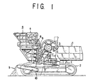
- a traveling type crushing machine includes a vehicle body 1.
- This vehicle body 1 has mounted thereto at both lower left hand side and lower right hand side a pair of traveling bodies 2, and has a crusher 3 and a hopper 4 mounted thereon.
- the said crusher 3 is provided in a housing 5 with a fixed jaw 6 and a swing jaw 7 so that by swingingly reciprocating the said swing jaw 7 towards and away from the said fixed jaw 6, a crushing of objects a to be crushed may be effected between it and the said fixed jaw 6.
- the said hopper 4 is equipped with a movable bottom plate 9 which constitutes a feeder 8 so that when the movable bottom plate 9 is reciprocated the objects to be crushed a may be fed into the said crusher 3.
- a belt conveyer 10 which is arranged to discharge the crushed pieces b out of the vehicle body 1.
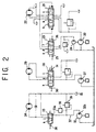
- Fig. 2 shows a hydraulic circuit of a certain embodiment of the crusher system drive control apparatus according to the present invention.
- a pressurized discharge fluid of a first primary hydraulic pump 20 is designed to be controlledly delivered to a crusher driving hydraulic motor 22 via a crusher switching valve 21.
- the said crusher switching valve 21 is normally held at its neutral position a and is adapted to be switched to a normally rotary position b and a reversely rotary position c under a pressurized discharge fluid of an auxiliary hydraulic pump 24 that is supplied from a pilot valve 23.
- the said pilot valve 23 is normally held at its neutral position and is adapted to be switched to a normally rotary position e and a reversely rotary position f if a first solenoid 25 and a second solenoid 26 are electrically energized, respectively.
- a pressurized discharge fluid of a second primary hydraulic pump 27 is designed to be controlledly delivered to a feeder driving hydraulic motor 29 via a feeder switching valve 28.
- the said feeder switching valve 28 is normally held at its neutral position g and is adapted to be switched to a normally rotary position h and a reversely rotary position i if a first solenoid 30 and a second solenoid 31 are electrically energized, respectively.
- a pressurized discharge fluid of a third primary hydraulic pump 32 is designed to be controlledly delivered to a belt conveyer driving hydraulic motor 34 and a reservoir 35 via a belt conveyer switching valve 33.
- the said belt conveyer switching valve 33 is normally held at its drain position j and is adapted to be switched to its supply position k when a solenoid 36 is electrically energized.
- a circuit 37 defined between an inlet port 33a of the said conveyer switching valve 33 and a discharge port 32a of the said primary pump 32 is provided therein with a pressure switch 38 that is adapted to be turned on when the discharge pressure of the said third primary hydraulic pump 32 is in excess of a set pressure at a relief valve 39.
- a crusher switch 40, a feeder switch 41 and a belt conveyer switch 42 are each provided with a startup switch 43 and a stop switch 44 that is normally held on.
- the said stop switches 44 are connected in series with each other and are also connected via an emergency stop switch 45 and an abnormal condition operative switch 46 with a power supply 47.
- each of the said stop switches 44 is connected via a self hold contact 48a of a crusher relay 48 with a coil 48b, is connected via a self hold contact 49a of a feeder relay 49 with a coil 49b and is connected via a self hold contact 50a of a belt conveyer relay 50 with a coil 50b.
- a normally open contact 48c of the above mentioned crusher relay 48 is connected to the said first solenoid 25 of the above mentioned pilot valve 23.
- a normally open contact 49c of the above mentioned feeder relay 49 is connected to the said first solenoid 30 of the above mentioned feeder switching valve 28, and a normally open contact 50c of the above mentioned belt conveyer relay 50 is connected to the said solenoid 36 and the above mentioned belt conveyer switching valve 33.
- the above mentioned emergency stop switch 45 is normally held on whereas the above mentioned abnormal condition operative switch 48 is normally held on and will be turned off a predetermined time after the above mentioned pressure switch 38 is turned on.
- the said feeder relay 49 and the said belt conveyer relay 50 will be operated in a similar manner to that as mentioned previously to rotationally drive the said feeder driving hydraulic motor 29 and the said belt conveyer driving hydraulic motor 34 each in a normal direction so as to drive the said feeder and the said belt conveyer 10.
- both the said feeder relay 49 and the said belt conveyer relay 50 will each have a self hold function.
- the said stop switch 44 is turned off in this state, the said feeder and the belt conveyer 10 will be stopped each in a similar manner to that as mentioned previously.
- a switch which can be turned on and off by a remote control or a radio control can be incorporated in a circuit that connects the the said self hold contact of each relay as mentioned above to the said power supply 47.
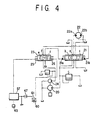
- FIG. 4 shows another crusher drive control hydraulic circuit according to the present invention.
- a pressurized discharge fluid of a primary hydraulic pump 20 is designed to be controlledly delivered to a crusher driving hydraulic motor 22 via a crusher switching valve 21.
- the said crusher switching valve 21 is normally held at its neutral position a and is adapted to be switched to a normally rotary position b and a reversely rotary position c each with a pressurized discharge fluid of an auxiliary hydraulic pump 24 that is supplied from a pilot valve 23.
- the said pilot valve 23 is normally held at its neutral position and is adapted to be switched to a normally rotary position e and a reversely rotary position f if a first solenoid 25 and a second solenoid 26 are electrically energized, respectively.
- the above mentioned first solenoid 25 is connected to a power supply 47 via a relay 57 which is controlled by an actuating switch 43 whereas the above mentioned second solenoid 26 is connected to the said power supply 47 via a push bottom switch 60 which is normally biased off by a spring 61.
- the said switch 60 is adapted to be turned on by pushing it against the said spring 61.
- the said relay 57 will be turned on by operating the said actuating switch 43 to electrically energize the said first solenoid 25 which will then act to switch the said pilot valve 23 to the normally rotary position e . Then, the said crusher switching valve 21 will, supplied with the pressurized discharge fluid of the said auxiliary hydraulic pump 24 at its first pressure receiving portion 21a, assume to take the normally rotary position b .
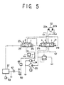
- Fig. 5 shows still another embodiment of the crusher drive control hydraulic circuit.
- a timer 62 is shown as interposed between the said switch 60 and the said second solenoid 26.
Landscapes
- Engineering & Computer Science (AREA)
- Food Science & Technology (AREA)
- Disintegrating Or Milling (AREA)
- Crushing And Grinding (AREA)
Claims (7)
- Fahrbare Zerkleinerungsmaschine mit einem Fahrzeugkörper (1), der mit einer Fortbewegungseinrichtung (2) ausgestattet ist und auf dem ein Brechwerksystem (3-10) mit einer Zuführeinrichtung (8), einem Brechwerk (3), einem Förderband (10) und einer Antriebssteuerung angebracht ist, wobei die Antriebssteuerung gekennzeichnet ist durch:eine Ausnahmezustand-Detektoreinrichtung (38) zum Erfassen eines außerplanmäßigen Stopps des Förderbandes (10), undeine Betriebs-Abschalteinrichtung (40-50), die auf ein Detektorsignal reagiert, das von der Ausnahmezustand-Detektoreinrichtung ausgegeben wird, um den Betrieb der Zuführeinrichtung und des Brechwerks wenigstens zu stoppen.
- Fahrbare Zerkleinerungsmaschine nach Anspruch 1, enthaltend:wobei die Ausnahmezustand-Detektoreinrichtung einen Druckschalter (38) enthält, der auf den Druck des dem hydraulischen Förderband-Antriebsmotor (34) zugeführten Fluids reagiert, der einen vorbestimmten Druckwert überschreitet; undein Zuführeinrichtungs-Umschaltventil (28) zum Zuführen eines Druckfluids zu einem hydraulischen Zuführeinrichtungs-Antriebsmotor (29);ein Brechwerk-Umschaltventil (21) zum Zuführen eines Druckfluids zu einem hydraulischen Brechwerk-Antriebsmotor (22);ein Förderband-Umschaltventil (33) zum Zuführen eines Druckfluids zu einem hydraulischen Förderband-Antriebsmotor (34);
die Betriebs-Abschalteinrichtung eine elektrische Schaltung (40-50) enthält, die auf ein Detektorsignal reagiert, das vom Drückschalter (38) ausgegeben wird, um jedes der Umschaltventile (21, 28, 33) in eine Druckfluid-Zuführstopposition zu schalten. - Fahrbare Zerkleinerungsmaschine nach Anspruch 2, bei der die elektrische Schaltung (40-50) enthält:wobei das Detektorsignal vom Druckschalter (38) auf den Ausnahmezustand-Betriebsschalter derart wirkt, daß er ausgeschaltet wird.eine Umschalteinrichtung (25, 30, 36), die mit jedem der Umschaltventile (21, 28, 33) verbunden ist und auf ein elektrisches Signal reagiert, das ihr zugesendet wird, um jedes Umschaltventil entweder in eine Druckfluid-Zuführposition oder eine Druckfluid-Zuführstopposition zu schalten;ein Zuführeinrichtungsrelais (49), das mit der Umschalteinrichtung (41) für das Zuführeinrichtungs-Umschaltventil (28) verbunden ist;einen Zuführeinrichtungsschalter (41) zum Ansteuern des Zuführeinrichtungsrelais' (49);ein Brechwerkrelais (48), das mit der Umschalteinrichtung (25) für das Brechwerk-Umschaltrelais (21) verbunden ist;einen Brechwerkschalter (40) zum Ansteuern des Brechwerkrelais (48);ein Förderbandrelais (50), das mit der Umschalteinrichtung (36) für das Förderband-Umschaltventil (33) verbunden ist;einen Förderbandschalter (42) zum Ansteuern des Förderbandrelais (50), undeinen Ausnahmezustand-Betriebsschalter (46), der normalerweise eingeschaltet ist und in einer Schaltung angebracht ist, die einen Selbsthaltekontakt jedes der Relais' mit einer Spannungsquelle (47) verbindet,
- Fahrbare Zerkleinerungsmaschine nach Anspruch 3, bei der ein Notausschalter (45) seriell mit dem Ausnahmezustand-Betriebsschalter (46) in einer Schaltung verbunden ist, die den Selbsthaltekontakt des Relais' mit der Spannungsquelle verbindet.
- Fahrbare Zerkleinerungsmaschine nach Anspruch 3 oder 4, bei der:die Umschalteinrichtung (30, 36) für das Zuführeinrichtungs-Umschaltventil (28) und die Umschalteinrichtung für das Förderband-Umschaltventil (33) jeweils ein Solenoid enthält, unddie Umschalteinrichtung (23, 25, 26) für das Brechwerk-Umschaltventil ein Steuerventil (23) enthält, das mit dem Solenoid (25, 26) angesteuert wird.
- Fahrbare Zerkleinerungsmaschine nach wenigstens einem der vorhergehenden Ansprüche, dadurch gekennzeichnet, daßdas Brechwerk-Umschaltventil (21) zum Zuführen eines Druckfluids zum hydraulischen Brechwerk-Antriebsmotor (22) dazu eingerichtet ist, von seiner Neutralposition alternativ in eine Normaldrehposition und eine Umkehrdrehposition durch das Steuerventil (23) umgeschaltet zu werden, das durch ein erstes Solenoid (25) bzw. ein zweites Solenoid (26) angesteuert wird, undein Schalter (60) zwischen einer Spannungsquelle (47) und dem zweiten Solenoid (26) angeordnet ist, den dazu eingerichtet ist, das Steuerventil in eine Position zu schalten, die ihrerseits dazu eingerichtet ist, das Brechwerk-Umschaltventil in die Umkehrdrehposition zu schalten.
- Fahrbare Zerkleinerungsmaschine nach einem der vorangehenden Ansprüche, dadurch gekennzeichnet, daß ein Zeitgeber (62) zwischen dem Schalter (60) und dem zweiten Solenoid (26) angeordnet ist.
Applications Claiming Priority (7)
| Application Number | Priority Date | Filing Date | Title |
|---|---|---|---|
| JP334010/93 | 1993-12-28 | ||
| JP33412593A JP3494230B2 (ja) | 1993-12-28 | 1993-12-28 | 移動式破砕機の駆動制御装置 |
| JP33412593 | 1993-12-28 | ||
| JP05334010A JP3117054B2 (ja) | 1993-12-28 | 1993-12-28 | 自走式破砕機の破砕機駆動制御装置 |
| JP33401093 | 1993-12-28 | ||
| JP334125/93 | 1993-12-28 | ||
| PCT/JP1994/002273 WO1995017969A1 (fr) | 1993-12-28 | 1994-12-27 | Appareil de commande de systeme de concassage pour concasseurs mobiles |
Publications (3)
| Publication Number | Publication Date |
|---|---|
| EP0737516A1 EP0737516A1 (de) | 1996-10-16 |
| EP0737516A4 EP0737516A4 (de) | 1998-04-15 |
| EP0737516B1 true EP0737516B1 (de) | 2002-03-13 |
Family
ID=26574706
Family Applications (1)
| Application Number | Title | Priority Date | Filing Date |
|---|---|---|---|
| EP95904007A Expired - Lifetime EP0737516B1 (de) | 1993-12-28 | 1994-12-27 | Fahrbare zerkleinerungsanlagen mit einem steuerungssystem |
Country Status (5)
| Country | Link |
|---|---|
| US (1) | US5730373A (de) |
| EP (1) | EP0737516B1 (de) |
| KR (1) | KR100207760B1 (de) |
| DE (1) | DE69430138T2 (de) |
| WO (1) | WO1995017969A1 (de) |
Cited By (1)
| Publication number | Priority date | Publication date | Assignee | Title |
|---|---|---|---|---|
| DE10215475A1 (de) * | 2002-04-09 | 2003-11-06 | Forus Gmbh | Hydraulischer Antrieb für eine Zerkleinerungsmaschine |
Families Citing this family (10)
| Publication number | Priority date | Publication date | Assignee | Title |
|---|---|---|---|---|
| KR0167853B1 (ko) * | 1995-01-23 | 1999-01-15 | 안자키 사토루 | 이동식 크러셔 및 크러셔의 제어방법 |
| JP3416843B2 (ja) * | 1998-06-22 | 2003-06-16 | 日精樹脂工業株式会社 | 竪型射出成形機の安全装置 |
| GB9904438D0 (en) * | 1999-02-26 | 1999-04-21 | Errut Prod Ltd | An apparatus and a method for recycling ground material |
| JP2003053203A (ja) * | 2001-08-16 | 2003-02-25 | Komatsu Ltd | ジョークラッシャ |
| GB0215441D0 (en) * | 2002-07-04 | 2002-08-14 | Extec Ind Plc | A crusher machine |
| DE10333359B3 (de) * | 2003-07-23 | 2005-01-20 | Vecoplan Maschinenfabrik Gmbh & Co. Kg | Zerkleinerungsvorrichtung für Abfälle |
| EP2837583B1 (de) * | 2013-08-14 | 2015-10-14 | Sandvik Intellectual Property AB | Mobile Vorrichtung zur Verarbeitung von Schüttgut mit Schwenkförderer |
| CN104675773B (zh) * | 2015-03-06 | 2016-11-23 | 浙江大学 | 一种辊压速度精准调控的辊压机纯水液压系统及其方法 |
| CN105536918B (zh) * | 2016-01-29 | 2017-12-08 | 陈安 | 一种带监控的微型颚式破碎机 |
| US20230095438A1 (en) * | 2021-09-30 | 2023-03-30 | Curtis Randolph | Automotive hydraulic system smart monitor and safety systems and devices |
Citations (1)
| Publication number | Priority date | Publication date | Assignee | Title |
|---|---|---|---|---|
| SU888013A1 (ru) * | 1979-04-26 | 1981-12-07 | Всесоюзный Научно-Исследовательский Институт Нерудных Строительных Материалов И Гидромеханизации (Вниинеруд) | Устройство дл контрол процесса дроблени и классификации |
Family Cites Families (8)
| Publication number | Priority date | Publication date | Assignee | Title |
|---|---|---|---|---|
| US4793561A (en) * | 1982-05-24 | 1988-12-27 | Mac Corporation Of America | Speed-responsive reversing hydraulic drive for rotary shredder |
| US4721257A (en) * | 1986-12-04 | 1988-01-26 | Williams Patent Crusher And Pulverizer Company | Rotary shredding apparatus |
| US4988045A (en) * | 1987-04-13 | 1991-01-29 | American Pulverizer Company | Vertical scrap metal crusher |
| JPH044029A (ja) * | 1990-04-21 | 1992-01-08 | Sugiyama Juko Kk | 回転容器型混合機 |
| US5074435A (en) * | 1990-06-01 | 1991-12-24 | Don Suverkrop, Inc. | System for controlling the feed rate of a vibrating feeder |
| JP2682744B2 (ja) * | 1990-12-10 | 1997-11-26 | 日鉄鉱業株式会社 | 破砕プラントの原料供給量制御方法及びその装置 |
| JP3359650B2 (ja) * | 1991-12-03 | 2002-12-24 | メッツォ・ミネラルズ・ジャパン株式会社 | 移動式クラッシャ |
| US5566893A (en) * | 1993-03-22 | 1996-10-22 | Getz; Roland A. | Portable recycle crusher |
-
1994
- 1994-12-27 EP EP95904007A patent/EP0737516B1/de not_active Expired - Lifetime
- 1994-12-27 US US08/663,196 patent/US5730373A/en not_active Expired - Lifetime
- 1994-12-27 DE DE69430138T patent/DE69430138T2/de not_active Expired - Fee Related
- 1994-12-27 WO PCT/JP1994/002273 patent/WO1995017969A1/ja not_active Ceased
- 1994-12-27 KR KR1019960703424A patent/KR100207760B1/ko not_active Expired - Fee Related
Patent Citations (1)
| Publication number | Priority date | Publication date | Assignee | Title |
|---|---|---|---|---|
| SU888013A1 (ru) * | 1979-04-26 | 1981-12-07 | Всесоюзный Научно-Исследовательский Институт Нерудных Строительных Материалов И Гидромеханизации (Вниинеруд) | Устройство дл контрол процесса дроблени и классификации |
Non-Patent Citations (1)
| Title |
|---|
| DATABASE WPI Week 8240, 17 December 1981 Derwent World Patents Index; AN 1982-N2075E, MATYUSHKIN E N: "CRUSHER-SORTER CONTROL SYSTEM FOR NON-METALS" * |
Cited By (2)
| Publication number | Priority date | Publication date | Assignee | Title |
|---|---|---|---|---|
| DE10215475A1 (de) * | 2002-04-09 | 2003-11-06 | Forus Gmbh | Hydraulischer Antrieb für eine Zerkleinerungsmaschine |
| DE10215475B4 (de) * | 2002-04-09 | 2007-05-16 | Forus Gmbh | Hydraulischer Antrieb für eine Zerkleinerungsmaschine |
Also Published As
| Publication number | Publication date |
|---|---|
| EP0737516A4 (de) | 1998-04-15 |
| US5730373A (en) | 1998-03-24 |
| DE69430138D1 (de) | 2002-04-18 |
| WO1995017969A1 (fr) | 1995-07-06 |
| EP0737516A1 (de) | 1996-10-16 |
| KR100207760B1 (ko) | 1999-07-15 |
| DE69430138T2 (de) | 2002-07-18 |
Similar Documents
| Publication | Publication Date | Title |
|---|---|---|
| EP0737516B1 (de) | Fahrbare zerkleinerungsanlagen mit einem steuerungssystem | |
| US5803376A (en) | Crushing machine control system for a self-traveling crushing machine vehicle | |
| US5230475A (en) | Conveyor system for shredder | |
| US5797548A (en) | Self-propelled crushing machine | |
| EP0685264B1 (de) | Mobile brecheranlage | |
| JP3953658B2 (ja) | 樹枝粉砕機 | |
| JP3494230B2 (ja) | 移動式破砕機の駆動制御装置 | |
| US5716014A (en) | Self-advancing crushing machine | |
| US8360349B1 (en) | Rotary grinder control system and method | |
| KR101041424B1 (ko) | 자주식 리사이클기의 주행제어장치 | |
| US20040200911A1 (en) | Crushing control apparatus for shearing crusher | |
| JP2000325829A (ja) | 自走式破砕機のフィーダ制御装置 | |
| CN112619870A (zh) | 具有改进的操作面板的岩石加工机 | |
| JP3294719B2 (ja) | 破砕機の駆動装置 | |
| JP3327733B2 (ja) | 破砕機 | |
| JP3117054B2 (ja) | 自走式破砕機の破砕機駆動制御装置 | |
| JPH11165842A (ja) | 搬送経路の搬送物有無検出装置 | |
| JP3166947B2 (ja) | 自走式破砕機械 | |
| JP4208183B2 (ja) | 自走式破砕機 | |
| JP4753298B2 (ja) | 破砕機における搬出コンベア制御装置 | |
| JP3681027B2 (ja) | 自走式破砕機 | |
| JP4787429B2 (ja) | 土質改良装置用破砕混合機の制御装置 | |
| JPH11333318A (ja) | 破砕機の破砕制御システム | |
| JP2000225356A (ja) | 破砕機の破砕制御システム | |
| JPH01168363A (ja) | 破砕プラントのコントロールシステム |
Legal Events
| Date | Code | Title | Description |
|---|---|---|---|
| PUAI | Public reference made under article 153(3) epc to a published international application that has entered the european phase |
Free format text: ORIGINAL CODE: 0009012 |
|
| 17P | Request for examination filed |
Effective date: 19960621 |
|
| AK | Designated contracting states |
Kind code of ref document: A1 Designated state(s): DE IT SE |
|
| A4 | Supplementary search report drawn up and despatched |
Effective date: 19980225 |
|
| AK | Designated contracting states |
Kind code of ref document: A4 Designated state(s): DE IT SE |
|
| 17Q | First examination report despatched |
Effective date: 20000328 |
|
| GRAG | Despatch of communication of intention to grant |
Free format text: ORIGINAL CODE: EPIDOS AGRA |
|
| RTI1 | Title (correction) |
Free format text: MOBILE CRUSHER WITH A DRIVE CONTROL APPARATUS |
|
| GRAG | Despatch of communication of intention to grant |
Free format text: ORIGINAL CODE: EPIDOS AGRA |
|
| GRAH | Despatch of communication of intention to grant a patent |
Free format text: ORIGINAL CODE: EPIDOS IGRA |
|
| GRAH | Despatch of communication of intention to grant a patent |
Free format text: ORIGINAL CODE: EPIDOS IGRA |
|
| GRAA | (expected) grant |
Free format text: ORIGINAL CODE: 0009210 |
|
| AK | Designated contracting states |
Kind code of ref document: B1 Designated state(s): DE IT SE |
|
| PG25 | Lapsed in a contracting state [announced via postgrant information from national office to epo] |
Ref country code: IT Free format text: LAPSE BECAUSE OF FAILURE TO SUBMIT A TRANSLATION OF THE DESCRIPTION OR TO PAY THE FEE WITHIN THE PRESCRIBED TIME-LIMIT;WARNING: LAPSES OF ITALIAN PATENTS WITH EFFECTIVE DATE BEFORE 2007 MAY HAVE OCCURRED AT ANY TIME BEFORE 2007. THE CORRECT EFFECTIVE DATE MAY BE DIFFERENT FROM THE ONE RECORDED. Effective date: 20020313 |
|
| REF | Corresponds to: |
Ref document number: 69430138 Country of ref document: DE Date of ref document: 20020418 |
|
| PG25 | Lapsed in a contracting state [announced via postgrant information from national office to epo] |
Ref country code: SE Free format text: LAPSE BECAUSE OF FAILURE TO SUBMIT A TRANSLATION OF THE DESCRIPTION OR TO PAY THE FEE WITHIN THE PRESCRIBED TIME-LIMIT Effective date: 20020613 |
|
| PLBE | No opposition filed within time limit |
Free format text: ORIGINAL CODE: 0009261 |
|
| STAA | Information on the status of an ep patent application or granted ep patent |
Free format text: STATUS: NO OPPOSITION FILED WITHIN TIME LIMIT |
|
| 26N | No opposition filed |
Effective date: 20021216 |
|
| PG25 | Lapsed in a contracting state [announced via postgrant information from national office to epo] |
Ref country code: DE Free format text: LAPSE BECAUSE OF NON-PAYMENT OF DUE FEES Effective date: 20030701 |