EP0734874A2 - Dispositif pour le transport de feuilles - Google Patents
Dispositif pour le transport de feuilles Download PDFInfo
- Publication number
- EP0734874A2 EP0734874A2 EP96104911A EP96104911A EP0734874A2 EP 0734874 A2 EP0734874 A2 EP 0734874A2 EP 96104911 A EP96104911 A EP 96104911A EP 96104911 A EP96104911 A EP 96104911A EP 0734874 A2 EP0734874 A2 EP 0734874A2
- Authority
- EP
- European Patent Office
- Prior art keywords
- original
- opposed
- rotary member
- sheet conveying
- holder
- Prior art date
- Legal status (The legal status is an assumption and is not a legal conclusion. Google has not performed a legal analysis and makes no representation as to the accuracy of the status listed.)
- Granted
Links
Images


Classifications
-
- B—PERFORMING OPERATIONS; TRANSPORTING
- B41—PRINTING; LINING MACHINES; TYPEWRITERS; STAMPS
- B41J—TYPEWRITERS; SELECTIVE PRINTING MECHANISMS, i.e. MECHANISMS PRINTING OTHERWISE THAN FROM A FORME; CORRECTION OF TYPOGRAPHICAL ERRORS
- B41J13/00—Devices or arrangements of selective printing mechanisms, e.g. ink-jet printers or thermal printers, specially adapted for supporting or handling copy material in short lengths, e.g. sheets
- B41J13/10—Sheet holders, retainers, movable guides, or stationary guides
- B41J13/103—Sheet holders, retainers, movable guides, or stationary guides for the sheet feeding section
-
- H—ELECTRICITY
- H04—ELECTRIC COMMUNICATION TECHNIQUE
- H04N—PICTORIAL COMMUNICATION, e.g. TELEVISION
- H04N1/00—Scanning, transmission or reproduction of documents or the like, e.g. facsimile transmission; Details thereof
- H04N1/024—Details of scanning heads ; Means for illuminating the original
- H04N1/028—Details of scanning heads ; Means for illuminating the original for picture information pick-up
- H04N1/03—Details of scanning heads ; Means for illuminating the original for picture information pick-up with photodetectors arranged in a substantially linear array
- H04N1/031—Details of scanning heads ; Means for illuminating the original for picture information pick-up with photodetectors arranged in a substantially linear array the photodetectors having a one-to-one and optically positive correspondence with the scanned picture elements, e.g. linear contact sensors
-
- H—ELECTRICITY
- H04—ELECTRIC COMMUNICATION TECHNIQUE
- H04N—PICTORIAL COMMUNICATION, e.g. TELEVISION
- H04N1/00—Scanning, transmission or reproduction of documents or the like, e.g. facsimile transmission; Details thereof
- H04N1/04—Scanning arrangements, i.e. arrangements for the displacement of active reading or reproducing elements relative to the original or reproducing medium, or vice versa
- H04N1/12—Scanning arrangements, i.e. arrangements for the displacement of active reading or reproducing elements relative to the original or reproducing medium, or vice versa using the sheet-feed movement or the medium-advance or the drum-rotation movement as the slow scanning component, e.g. arrangements for the main-scanning
- H04N1/121—Feeding arrangements
- H04N1/1215—Feeding using one or more cylindrical platens or rollers in the immediate vicinity of the main scanning line
-
- H—ELECTRICITY
- H04—ELECTRIC COMMUNICATION TECHNIQUE
- H04N—PICTORIAL COMMUNICATION, e.g. TELEVISION
- H04N1/00—Scanning, transmission or reproduction of documents or the like, e.g. facsimile transmission; Details thereof
- H04N1/04—Scanning arrangements, i.e. arrangements for the displacement of active reading or reproducing elements relative to the original or reproducing medium, or vice versa
- H04N1/19—Scanning arrangements, i.e. arrangements for the displacement of active reading or reproducing elements relative to the original or reproducing medium, or vice versa using multi-element arrays
- H04N1/191—Scanning arrangements, i.e. arrangements for the displacement of active reading or reproducing elements relative to the original or reproducing medium, or vice versa using multi-element arrays the array comprising a one-dimensional array, or a combination of one-dimensional arrays, or a substantially one-dimensional array, e.g. an array of staggered elements
- H04N1/192—Simultaneously or substantially simultaneously scanning picture elements on one main scanning line
- H04N1/193—Simultaneously or substantially simultaneously scanning picture elements on one main scanning line using electrically scanned linear arrays, e.g. linear CCD arrays
-
- H—ELECTRICITY
- H04—ELECTRIC COMMUNICATION TECHNIQUE
- H04N—PICTORIAL COMMUNICATION, e.g. TELEVISION
- H04N2201/00—Indexing scheme relating to scanning, transmission or reproduction of documents or the like, and to details thereof
- H04N2201/024—Indexing scheme relating to scanning, transmission or reproduction of documents or the like, and to details thereof deleted
- H04N2201/02402—Arrangements for positioning heads, e.g. with respect to other elements of the apparatus
-
- H—ELECTRICITY
- H04—ELECTRIC COMMUNICATION TECHNIQUE
- H04N—PICTORIAL COMMUNICATION, e.g. TELEVISION
- H04N2201/00—Indexing scheme relating to scanning, transmission or reproduction of documents or the like, and to details thereof
- H04N2201/024—Indexing scheme relating to scanning, transmission or reproduction of documents or the like, and to details thereof deleted
- H04N2201/02404—Arrangements for mounting or supporting heads
Definitions
- the present invention relates to a sheet conveying apparatus for conveying a sheet such as an original, a recording sheet and the like, and more particularly, it relates to an original reading apparatus used with a facsimile system and the like.
- the reference numeral 51 denotes an original convey roller for conveying an original
- 52 denotes an image sensor of complete contact type (referred to as “contact sensor” or “CS” hereinafter) acting as a reading device for reading image information on the original
- 53 denotes a holder for locking and holding the CS 52
- 54 denotes an urging means for urging the CS 52 against the original convey roller through the holder 53.
- the holder 53 has a rotary support portion 53a for attaching the holder 53 to a body of the apparatus for rocking movement, and a guide portion 53b for guiding the holder when the holder is engaged by the body of the apparatus.
- the coefficient ⁇ 1 of friction between the original convey roller 51 and the original 6 must be greater than the coefficient ⁇ 2 of friction between the original 6 and the CS 52 ( ⁇ 1 > ⁇ 2).
- a surface of the original convey roller 51 is constituted by elastic material such as rubber.
- the original convey roller 51 is rotated in the original conveying direction b by detection of sensor(s) (not shown) and/or by manual input through an operation portion (not shown).
- sensor(s) not shown
- the CS 52 and the holder 53 for holding the CS are subjected to a conveying force F2 (in the original conveying direction a) corresponding to the above-mentioned resistance force F2, as shown in Fig. 7.
- the positioning of the CS 52 and the holder 53 for holding the CS regarding the original conveying direction a is effected by fitting a U-shaped notch 53c (Fig. 6) of the guide portion 53b of the holder 53 on a shaft 51a of the original convey roller 51.
- any load acting on an original convey driving system such as a motor (drive source) for rotating the original convey roller 51 is also maximized. Since the U-shaped notch 53c of the guide portion 53b of the holder 53 is fitted on the shaft 51a of the original convey roller 51, the holder 53 is subjected to a force F4 (directing toward a direction opposite to the original conveying direction a) same as the above-mentioned conveying force F3 from the rotating shaft 51a of the original convey roller 51.
- a force F4 directing toward a direction opposite to the original conveying direction a
- the urging force of the CS 52 against the original convey roller 51 is increased. If such urging force is increased, the conveying force F3 received by the CS 52 from the original convey roller 51 is further increased, with the result that the couple of forces is further increased to further increase the urging force of the CS 52 against the original convey roller 51 (vicious circle). As a result, the load acting on the drive system (not shown) of the original reading apparatus is greatly increased.
- the present invention aims to eliminate the above-mentioned conventional drawbacks, and an object of the present invention is to provide a sheet conveying apparatus and an original reading apparatus which can reduce a load of a drive system for driving a convey rotary member and can be made compact.
- a sheet conveying apparatus comprising a rotary member for conveying a sheet and an opposed member (counter member) biased toward the rotary member by a biasing means.
- the sheet is conveyed between the rotary member and the opposed member by rotation of the rotary member, and when the rotary member is rotated and the opposed member is subjected to a force directing toward a rotational direction of the rotary member due to friction between the rotary member and the opposed member or friction between the sheet and the opposed member, an urging force of the opposed member against the rotary member is decreased.
- the present invention provides a sheet conveying apparatus comprising a rotary member supported by a shaft to convey a sheet, and an opposed member rotatable around a rotation shaft and biased toward the rotary member by a biasing means.
- the sheet is conveyed between the rotary member and the opposed member by rotation of the rotary member, and it comprises a holding member for regulating a position of the rotation shaft of the opposed member in a thickness-wise direction, and a positioning member for regulating a position of the opposed member in a sheet conveying direction.
- the opposed member when the rotary member is rotated in a condition that the sheet does not exist between the rotary member and the opposed member, the opposed member is subjected to a force directing toward a rotational direction of the rotary member due to friction between the rotary member and the opposed member so that the opposed member abuts against the positioning member to position the opposed member in the sheet conveying direction, and, couple of forces generated at a contact point between the opposed member and the rotary member and couple of forces generated at a contact point between the opposed member and the positioning member due to the rotation of the rotary member act to separate the opposed member from the rotary member.
- the rotation shaft of the opposed member may be located upstream of the rotary member in the sheet conveying direction, or, the position of the rotation shaft of the opposed member may be located toward the opposed member side with respect to the rotary member in a sheet thickness-wise direction.
- the sheet conveying apparatus can be incorporated into an original reading apparatus.
- the rotary member acts as an original convey rotary member
- the opposed member acts as an original reading means.
- the sheet conveying apparatus Since the sheet conveying apparatus according to the present invention has the above-mentioned construction and operation, if there is no sheet between the rotary member and the opposed member and the load of the convey drive system is great, the load can be decreased. When the sheet exists between the rotary member and the opposed member, the sheet conveying ability of the rotary member is not worsened. Further, since the rotary member and the opposed member can be disposed in the vicinity of a sheet discharge opening of the apparatus, the entire apparatus can be made compact. In addition, since the rotation shaft of the opposed member can be disposed within a sheet path area in a sheet width-wise direction, the entire apparatus can be further made compact.
- the support member for rotatably supporting the rotary member, the holding member for holding the biasing means, the rotation shaft holding member for holding the rotation shaft of the opposed member, and the positioning member for positioning the position of the opposed member in the sheet conveying direction are integrally constructed, the number of parts can be reduced, thereby making the apparatus cheaper.
- the original reading apparatus having the above-mentioned sheet conveying apparatus can be made compact by the features of the sheet conveying apparatus itself and can be made cheaper by reducing the number of parts.
- an original convey roller 1 acts as a convey rotary member for conveying an original 6 formed from paper sheet or synthetic resin film, and a surface of the original convey roller 1 is constituted by elastic material such as rubber.
- An image sensor of complete contact type (referred to as “contact sensor” or “CS” hereinafter) 2 acts as an original reading means for reading image information on the original 6.
- the CS 2 is locked and held by a holder 3 at several points along the entire width of the CS.
- the holder 3 can be rocked around a rotation shaft 3a held by a holder rotation shaft holding portion (rotation shaft holding member) 5a, and the holder rotation shaft holding portion 5a serves to regulate a position of the rotation shaft 3a in a thickness-wise direction of the original 6 so that a position of the CS 2 in the thickness-wise direction of the original 6 is set when the CS 2 is opposed to the original convey roller 1 and further serves to slidably holding the rotation shaft 3a for sliding movement in an original conveying direction.
- Positioning abutment portions 3b serve to regulate a position of the holder 3 in the original conveying direction.
- the positioning abutment portions 3b abut against a holder stopper portion (positioning abutment member) 5b formed on a frame 5
- the position of the holder 3 in the original conveying direction is regulated so that the position of the CS 2 in the original conveying direction is set when the CS 2 is opposed to the original convey roller 1.
- the holder rotation shaft 3a and the positioning abutment portions 3b are integrally formed with the holder 3.
- An urging spring (biasing means) 4 for urging the holder 3 against the original convey roller 1 is held by an urging spring holding portion (biasing means holding member) 5c.
- the frame 5 acts as a base of the original reading apparatus and includes the above-mentioned holder rotation shaft holding portion 5a, holder stopper portion 5b, urging spring holding portion 5c, and an original convey roller supporting portion (not shown) acting as a convey rotary member support member for supporting the original convey roller 1.
- the CS 2 and the holder 3 rotatably supported by the frame 5 and urged against the original convey roller 1 constitute a convey rotary member opposed member.
- the rotation shaft 3a of the holder 3 is disposed between both ends of the holder 3 in a width-wise direction of the original 6 to be conveyed.
- the reason for providing the single rotation shaft 3a of the holder 3 is that an original conveying force of the original convey roller 1 is made uniform in the width-wise direction of the original 6.
- torsion is generated between the rotation shafts 3a of the holder 3 and the shaft 1a of the original convey roller 1, with the result that the urging force of the CS 2 against the original convey roller 1 becomes uneven in the width-wise direction of the original 6. Consequently, the proper original conveying ability cannot be obtained.
- two holder positioning abutment portions 3b are provided in a predetermined spaced relation along the width-wise direction of the original 6, so that, when the two holder positioning abutment portions 3b abut against the holder stopper portion 5b, a reading line of the CS 2 is closely contacted with the surface of the original convey roller 1 with high accuracy. With this arrangement, the holder 3 is prevented from rotating in the conveying plane of the original 6.
- the original convey roller 1 When the original 6 is inserted into the original reading apparatus having the above-mentioned construction, the original convey roller 1 is rotated in a direction shown by the arrow b in Fig. 1 by detection of sensor(s) (not shown) and/or by manual input through an operation portion (not shown), thereby conveying the original 6 in a direction shown by the arrow a in Fig. 1.
- the rotation shaft 3a can be shifted in the original conveying direction.
- the CS 2 is urged against the original convey roller 1 through the holder 3 by the urging spring 4, the CS 2 and the holder 3 are shifted in the original conveying direction a when subjected to the conveying force from the original convey roller 1. And, when the holder positioning abutment portions 3b abut against the holder stopper 5b, the position of the CS 2 in the original conveying direction is determined.
- the original 6 When the original 6 is inserted between the original convey roller 1 and the CS 2, as shown in Fig. 3, the original 6 is subjected to a conveying force F1 (directing toward the original conveying direction a) from the original convey roller 1 due to friction between the original convey roller 1 and the original 6 and is also subjected to a resistance force F2 (direction toward a direction opposite to the original conveying direction a) due to friction between the original 6 and the CS 2.
- a conveying force F1 directing toward the original conveying direction a
- F2 direction toward a direction opposite to the original conveying direction a
- the original 6 is conveyed to the original conveying direction a.
- the coefficient ⁇ 1 of friction between the original convey roller 1 and the original 6 must be greater than the coefficient ⁇ 2 of friction between the original 6 and the CS 2 ( ⁇ 1 > ⁇ 2).
- the surface of the original convey roller 1 is constituted by elastic material such as rubber.
- the CS 2 and the holder 3 for holding the CS are subjected to a conveying force F2 (in the original conveying direction a) corresponding to the above-mentioned resistance force F2 due to the friction between the CS 2 and the original 6.
- the CS 2 is subjected to a conveying force F3 from the original convey roller 1. Since an image information reading surface of the CS 2 is constituted by glass and the surface of the original convey roller 1 is constituted by rubber, the coefficient ⁇ 3 of friction between the original convey roller 1 and the CS 2 becomes greater than the friction coefficient ⁇ 2 ( ⁇ 3 > ⁇ 2), thereby establishing a relation F3 > F2. Thus, when there is no original 6 between the original convey roller 1 and the CS 2, the conveying force acting on the CS 2 will be maximum. Accordingly, when there is no original 6 between the original convey roller 1 and the CS 2, any load acting on an original convey driving system (not shown) such as a motor (drive source) is also maximized.
- an original convey driving system not shown
- a motor drive source
- the CS 2 and the associated holder 3 are subjected to the conveying force F3 directing toward the original conveying direction a and received from the original convey roller 1 at a contact point between the original convey roller 1 and the CS 2, and a drag force F4 received from the holder stopper 5b through the holder positioning abutment portions 3b.
- the drag force F4 has the same magnitude as the conveying force F3 but directs toward the direction opposite to the original conveying direction a.
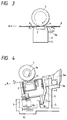
- the facsimile system comprises an upper reading system A and a lower recording system B.
- the original is conveyed as follows. First of all, when an original bundle 13 is inserted into an original insertion path 12 inclined by an angle of 30 - 40° with respect to a horizontal plane through an original insertion opening 11 of the facsimile system, the original bundle is detected by an original presence/absence sensor (not shown), and a signal from the sensor is sent to a control portion of the facsimile system, thereby ascertaining the presence of the original. Further, the original bundle 13 is inserted until it reaches an original separation portion 16 including an original separation piece 15 opposed to an original separation roller 14 and urged against the original separation roller 14 by a biasing means (not shown).
- a reading drive system By depressing a start key (not shown) on the operation portion, a reading drive system is operated to rotate the original separation roller 14 in an original bundle conveying direction.
- the original bundle is pinched between the rotating original separation roller 14 and the original separation piece 15 urged against the original separation roller 14, thereby separating the originals one by one.
- the separated original 6 is conveyed by the rotating original separation roller 14; meanwhile, a tip end of the original 6 is detected by an original end detection sensor.
- the original 6 is further conveyed by the rotating original separation roller 14 to reach an image information reading portion 17 including a CS 2 and an original convey roller 1 opposed to the CS 2.
- the CS 2 is urged against the original convey roller 1 by an urging spring 4.
- the original 6 reached the image information reading portion 17 is inserted between the original convey roller 1 and the CS 2, so that the image information on the original is read by the CS 2 while the original 6 is being conveyed by the rotating original convey roller 1 in an original conveying direction.
- a trail end of the original is detected by the original end detection sensor, and the original is discharged out of the facsimile system by the original convey roller 1 through an original discharge opening 18.
- a recording sheet is conveyed as follows.
- a recording sheet stack 20 rested on a sheet stacking plate 19 is separated one by one by a separation roller 21.
- a recording sheet 22 separated by the separation roller 21 is conveyed up to a pair of convey rollers 23a, 23b opposed to each other with the interposition of a recording sheet convey path.
- the recording sheet is conveyed by the pair of convey rollers 23a, 23b up to an image recording position 24, where the recording sheet 22 is temporarily stopped and held in the image recording position 24.
- ink is discharged from discharge openings of an ink jet recording head 25 disposed a confronting relation to an image record surface of the recording sheet 22, with the result that ink droplets is adhered to the image record surface of the recording sheet 22, thereby forming an image.
- the pair of convey rollers 23a, 23b are rotated again to convey the recording sheet by a predetermined amount. Then, the recording sheet 22 is stopped again, and next one-line recording is effected.
- the recording sheet 22 is discharged out of the facsimile system by a pair of discharge rollers 26a, 26b opposed to each other with the interposition of the recording sheet convey path. In this way, the recorded recording sheets are stacked in the vicinity of a discharge opening with imaged surfaces facing upside.
- the holder rotation shaft 3a is disposed at an upstream side of the image information reading portion 17 (i.e., a contact point between the original convey roller 1 and the CS 2) in the original conveying direction.
- the original convey roller 1, CS 2 and holder 3 can be disposed in the vicinity of the original discharge opening 18, thereby making the facsimile system compact.
- the holder rotation shaft 3a is disposed at the CS 2 side rather than the original convey roller 1 side in the thickness-wise direction of the original.
- the original passing area can be provided at the original convey roller 1 side rather than the CS 2 side in the thickness-wise direction of the original. That is to say, since the original passing area can be provided so that the holder rotation shaft 3a and the rotating action of the holder 3 do not interfere with the original convey path, the holder rotation shaft 3a can be disposed within the original passing area in the thickness-wise direction of the original, thereby making the facsimile system compact.
- the holder rotation shaft holding portion 5a for holding the holder rotation shaft 3a, the holder stopper portion 5b against which the holder positioning abutment portions 3b abut, the urging spring holding portion 5c for holding the urging spring 4, and an original convey roller supporting member (not shown) for rotatably supporting the original convey roller 1 are integrally formed with the frame 5, the number of parts can be reduced, thereby making the facsimile system cheaper.
- the force F4 acts toward a direction opposite to the direction in which the conveying force F3 of the original convey roller generated at a position for regulating the position of the holder in the original conveying direction acts on the CS and the holder.
- the drag force F6 (Fig. 3) having the same magnitude as the conveying force F2 and directing toward the direction opposite to the original conveying direction a acts on the holder positioning abutment portions 3b, the CS and the holder are subjected to the couple of forces tending to rotate the CS and the holder around the holder rotation shaft 3a in the direction d in Fig. 4.
- a sheet conveying apparatus and an original reading apparatus can reduce a load of a drive system for rotating a convey rotary member and can be made compact.
- the apparatus comprises an original convey roller 1 rotatably supported by a frame 5, and a CS holder 3 rockably held by a CS holder rotation shaft 3a regulated (in a thickness-wise direction of an original) by a CS holder rotation shaft holding portion 5a of the frame 5 and adapted to hold a CS 2 in a confronting relation to the original convey roller 1.
- the CS 2 is urged against the original convey roller 1 by an urging spring 4.
Applications Claiming Priority (3)
| Application Number | Priority Date | Filing Date | Title |
|---|---|---|---|
| JP6924895 | 1995-03-28 | ||
| JP06924895A JP3363649B2 (ja) | 1995-03-28 | 1995-03-28 | シート搬送装置および原稿読取装置 |
| JP69248/95 | 1995-03-28 |
Publications (3)
| Publication Number | Publication Date |
|---|---|
| EP0734874A2 true EP0734874A2 (fr) | 1996-10-02 |
| EP0734874A3 EP0734874A3 (fr) | 1998-02-04 |
| EP0734874B1 EP0734874B1 (fr) | 2003-10-15 |
Family
ID=13397262
Family Applications (1)
| Application Number | Title | Priority Date | Filing Date |
|---|---|---|---|
| EP96104911A Expired - Lifetime EP0734874B1 (fr) | 1995-03-28 | 1996-03-27 | Dispositif pour le transport de feuilles |
Country Status (4)
| Country | Link |
|---|---|
| US (1) | US5903365A (fr) |
| EP (1) | EP0734874B1 (fr) |
| JP (1) | JP3363649B2 (fr) |
| DE (1) | DE69630330T2 (fr) |
Cited By (1)
| Publication number | Priority date | Publication date | Assignee | Title |
|---|---|---|---|---|
| EP1013074A1 (fr) * | 1997-04-01 | 2000-06-28 | Storm Technology, Inc. | Dispositif d'exploration de document alimente en puissance par un bus peripherique |
Families Citing this family (9)
| Publication number | Priority date | Publication date | Assignee | Title |
|---|---|---|---|---|
| JP3684159B2 (ja) | 2001-01-31 | 2005-08-17 | キヤノン株式会社 | 記録装置および記録方法 |
| US7382506B2 (en) * | 2002-12-24 | 2008-06-03 | Canon Kabushiki Kaisha | Image reading and recording apparatus |
| JP2005341306A (ja) * | 2004-05-27 | 2005-12-08 | Brother Ind Ltd | 画像読取装置 |
| US7423280B2 (en) * | 2004-08-09 | 2008-09-09 | Quad/Tech, Inc. | Web inspection module including contact image sensors |
| US8004727B2 (en) * | 2007-07-16 | 2011-08-23 | Visioneer, Inc. | Automatically adjusting multi-media scanner |
| JP5935496B2 (ja) * | 2012-05-10 | 2016-06-15 | 富士ゼロックス株式会社 | シート搬送装置、画像読取装置及び画像形成装置 |
| JP5858888B2 (ja) * | 2012-09-14 | 2016-02-10 | 株式会社Pfu | 媒体搬送装置 |
| JP5911406B2 (ja) | 2012-09-14 | 2016-04-27 | 株式会社Pfu | 画像読取装置及び画像処理システム |
| US9479662B1 (en) * | 2016-03-17 | 2016-10-25 | Foxlink Image Technology Co., Ltd. | Adjustable scanning device |
Citations (5)
| Publication number | Priority date | Publication date | Assignee | Title |
|---|---|---|---|---|
| JPH0263369A (ja) * | 1988-08-30 | 1990-03-02 | Tohoku Pioneer Kk | ファクシミリ装置 |
| US5070415A (en) * | 1987-07-14 | 1991-12-03 | Canon Kabushiki Kaisha | Image reading apparatus having a low friction member between the conveying roller and the transparent plate |
| EP0485975A2 (fr) * | 1990-11-14 | 1992-05-20 | Canon Kabushiki Kaisha | Dispositif de lecture d'images |
| JPH06217073A (ja) * | 1992-04-09 | 1994-08-05 | Ricoh Unie Techno Kk | 画像読み取り装置 |
| EP0659009A2 (fr) * | 1993-12-17 | 1995-06-21 | Canon Kabushiki Kaisha | Dispositif de lecture d'original et dispositif de traitement d'information comportant un dispositif de lecture d'original |
Family Cites Families (5)
| Publication number | Priority date | Publication date | Assignee | Title |
|---|---|---|---|---|
| US4975787A (en) * | 1987-07-06 | 1990-12-04 | Canon Kabushiki Kaisha | Sheet conveying and reading apparatus |
| JP2766679B2 (ja) * | 1989-08-04 | 1998-06-18 | キヤノン株式会社 | 原稿搬送読取装置 |
| JP2656123B2 (ja) * | 1989-10-20 | 1997-09-24 | キヤノン株式会社 | 読取装置 |
| US5420701A (en) * | 1992-11-11 | 1995-05-30 | Canon Kabushiki Kaisha | Thin-type facsimile apparatus |
| JP3169745B2 (ja) * | 1993-06-30 | 2001-05-28 | 松下電送システム株式会社 | ファクシミリ装置 |
-
1995
- 1995-03-28 JP JP06924895A patent/JP3363649B2/ja not_active Expired - Fee Related
-
1996
- 1996-03-27 EP EP96104911A patent/EP0734874B1/fr not_active Expired - Lifetime
- 1996-03-27 DE DE69630330T patent/DE69630330T2/de not_active Expired - Lifetime
-
1997
- 1997-10-07 US US08/946,010 patent/US5903365A/en not_active Expired - Lifetime
Patent Citations (5)
| Publication number | Priority date | Publication date | Assignee | Title |
|---|---|---|---|---|
| US5070415A (en) * | 1987-07-14 | 1991-12-03 | Canon Kabushiki Kaisha | Image reading apparatus having a low friction member between the conveying roller and the transparent plate |
| JPH0263369A (ja) * | 1988-08-30 | 1990-03-02 | Tohoku Pioneer Kk | ファクシミリ装置 |
| EP0485975A2 (fr) * | 1990-11-14 | 1992-05-20 | Canon Kabushiki Kaisha | Dispositif de lecture d'images |
| JPH06217073A (ja) * | 1992-04-09 | 1994-08-05 | Ricoh Unie Techno Kk | 画像読み取り装置 |
| EP0659009A2 (fr) * | 1993-12-17 | 1995-06-21 | Canon Kabushiki Kaisha | Dispositif de lecture d'original et dispositif de traitement d'information comportant un dispositif de lecture d'original |
Non-Patent Citations (2)
| Title |
|---|
| PATENT ABSTRACTS OF JAPAN vol. 14, no. 239 (E-0930), 21 May 1990 & JP 02 063369 A (TOHOKU PIONNER KK), 2 March 1990, * |
| PATENT ABSTRACTS OF JAPAN vol. 18, no. 580 (E-1626), 7 November 1994 & JP 06 217073 A (RICOH UNIE TECHNO KK), 5 August 1994, * |
Cited By (2)
| Publication number | Priority date | Publication date | Assignee | Title |
|---|---|---|---|---|
| EP1013074A1 (fr) * | 1997-04-01 | 2000-06-28 | Storm Technology, Inc. | Dispositif d'exploration de document alimente en puissance par un bus peripherique |
| EP1013074A4 (fr) * | 1997-04-01 | 2003-04-02 | Storm Technology Inc | Dispositif d'exploration de document alimente en puissance par un bus peripherique |
Also Published As
| Publication number | Publication date |
|---|---|
| US5903365A (en) | 1999-05-11 |
| JPH08259032A (ja) | 1996-10-08 |
| EP0734874A3 (fr) | 1998-02-04 |
| DE69630330T2 (de) | 2004-05-13 |
| DE69630330D1 (de) | 2003-11-20 |
| EP0734874B1 (fr) | 2003-10-15 |
| JP3363649B2 (ja) | 2003-01-08 |
Similar Documents
| Publication | Publication Date | Title |
|---|---|---|
| US10526149B2 (en) | Image processing devices and sheet feeding devices | |
| US7055818B2 (en) | Sheet treating apparatus and image forming apparatus | |
| EP0528434A2 (fr) | Appareil automatique d'alimentation de feuilles | |
| WO1995018055A1 (fr) | Dispositif d'avance automatique du papier et cadre pour un dispositif d'introduction de documents | |
| EP0734874B1 (fr) | Dispositif pour le transport de feuilles | |
| US20060237895A1 (en) | Sheet feeding apparatus and image forming apparatus | |
| EP0728689B1 (fr) | Appareil d'alimentation en feuilles | |
| US7384034B2 (en) | Sheet convey apparatus | |
| EP0347887B1 (fr) | Dispositif pour séparer des feuilles | |
| US5157520A (en) | Device for transporting documents | |
| US6168150B1 (en) | Sheet feeder unit | |
| US6398205B1 (en) | Sheet feeder unit | |
| JPS5931625Y2 (ja) | 給紙装置 | |
| JP3378123B2 (ja) | 原稿分離搬送装置 | |
| JP3115211B2 (ja) | 媒体処理装置 | |
| US20040178563A1 (en) | Sheet feeding apparatus and image forming apparatus | |
| JP3978388B2 (ja) | シート材給送装置及びそれを備えた画像形成装置 | |
| JPH0618345U (ja) | 自動給紙装置 | |
| JP2858187B2 (ja) | シート材搬送装置 | |
| JP2833254B2 (ja) | 給紙装置 | |
| JP3833451B2 (ja) | 原稿自動分離装置及び画像形成装置 | |
| JP3559859B2 (ja) | 分離給紙装置 | |
| JP4084652B2 (ja) | シート体供給装置 | |
| JPS5859135A (ja) | 給紙装置 | |
| KR200186325Y1 (ko) | 급지카세트의용지픽업장치 |
Legal Events
| Date | Code | Title | Description |
|---|---|---|---|
| PUAI | Public reference made under article 153(3) epc to a published international application that has entered the european phase |
Free format text: ORIGINAL CODE: 0009012 |
|
| AK | Designated contracting states |
Kind code of ref document: A2 Designated state(s): DE ES FR GB IT |
|
| PUAL | Search report despatched |
Free format text: ORIGINAL CODE: 0009013 |
|
| RHK1 | Main classification (correction) |
Ipc: H04N 1/12 |
|
| AK | Designated contracting states |
Kind code of ref document: A3 Designated state(s): DE ES FR GB IT |
|
| 17P | Request for examination filed |
Effective date: 19980622 |
|
| 17Q | First examination report despatched |
Effective date: 20010620 |
|
| GRAH | Despatch of communication of intention to grant a patent |
Free format text: ORIGINAL CODE: EPIDOS IGRA |
|
| GRAS | Grant fee paid |
Free format text: ORIGINAL CODE: EPIDOSNIGR3 |
|
| GRAA | (expected) grant |
Free format text: ORIGINAL CODE: 0009210 |
|
| AK | Designated contracting states |
Kind code of ref document: B1 Designated state(s): DE ES FR GB IT |
|
| REG | Reference to a national code |
Ref country code: GB Ref legal event code: FG4D |
|
| REF | Corresponds to: |
Ref document number: 69630330 Country of ref document: DE Date of ref document: 20031120 Kind code of ref document: P |
|
| PG25 | Lapsed in a contracting state [announced via postgrant information from national office to epo] |
Ref country code: ES Free format text: LAPSE BECAUSE OF FAILURE TO SUBMIT A TRANSLATION OF THE DESCRIPTION OR TO PAY THE FEE WITHIN THE PRESCRIBED TIME-LIMIT Effective date: 20040126 |
|
| ET | Fr: translation filed | ||
| PLBE | No opposition filed within time limit |
Free format text: ORIGINAL CODE: 0009261 |
|
| STAA | Information on the status of an ep patent application or granted ep patent |
Free format text: STATUS: NO OPPOSITION FILED WITHIN TIME LIMIT |
|
| 26N | No opposition filed |
Effective date: 20040716 |
|
| PGFP | Annual fee paid to national office [announced via postgrant information from national office to epo] |
Ref country code: DE Payment date: 20120331 Year of fee payment: 17 |
|
| PGFP | Annual fee paid to national office [announced via postgrant information from national office to epo] |
Ref country code: GB Payment date: 20120223 Year of fee payment: 17 Ref country code: IT Payment date: 20120312 Year of fee payment: 17 |
|
| PGFP | Annual fee paid to national office [announced via postgrant information from national office to epo] |
Ref country code: FR Payment date: 20120413 Year of fee payment: 17 |
|
| GBPC | Gb: european patent ceased through non-payment of renewal fee |
Effective date: 20130327 |
|
| REG | Reference to a national code |
Ref country code: FR Ref legal event code: ST Effective date: 20131129 |
|
| REG | Reference to a national code |
Ref country code: DE Ref legal event code: R119 Ref document number: 69630330 Country of ref document: DE Effective date: 20131001 |
|
| PG25 | Lapsed in a contracting state [announced via postgrant information from national office to epo] |
Ref country code: DE Free format text: LAPSE BECAUSE OF NON-PAYMENT OF DUE FEES Effective date: 20131001 Ref country code: FR Free format text: LAPSE BECAUSE OF NON-PAYMENT OF DUE FEES Effective date: 20130402 Ref country code: GB Free format text: LAPSE BECAUSE OF NON-PAYMENT OF DUE FEES Effective date: 20130327 |
|
| PG25 | Lapsed in a contracting state [announced via postgrant information from national office to epo] |
Ref country code: IT Free format text: LAPSE BECAUSE OF NON-PAYMENT OF DUE FEES Effective date: 20130327 |