EP0733585A2 - Grue de chargement - Google Patents
Grue de chargement Download PDFInfo
- Publication number
- EP0733585A2 EP0733585A2 EP96890052A EP96890052A EP0733585A2 EP 0733585 A2 EP0733585 A2 EP 0733585A2 EP 96890052 A EP96890052 A EP 96890052A EP 96890052 A EP96890052 A EP 96890052A EP 0733585 A2 EP0733585 A2 EP 0733585A2
- Authority
- EP
- European Patent Office
- Prior art keywords
- hydraulic cylinder
- piston unit
- pivoting
- arm
- boom arm
- Prior art date
- Legal status (The legal status is an assumption and is not a legal conclusion. Google has not performed a legal analysis and makes no representation as to the accuracy of the status listed.)
- Withdrawn
Links
Images

Classifications
-
- B—PERFORMING OPERATIONS; TRANSPORTING
- B66—HOISTING; LIFTING; HAULING
- B66C—CRANES; LOAD-ENGAGING ELEMENTS OR DEVICES FOR CRANES, CAPSTANS, WINCHES, OR TACKLES
- B66C23/00—Cranes comprising essentially a beam, boom, or triangular structure acting as a cantilever and mounted for translatory of swinging movements in vertical or horizontal planes or a combination of such movements, e.g. jib-cranes, derricks, tower cranes
- B66C23/54—Cranes comprising essentially a beam, boom, or triangular structure acting as a cantilever and mounted for translatory of swinging movements in vertical or horizontal planes or a combination of such movements, e.g. jib-cranes, derricks, tower cranes with pneumatic or hydraulic motors, e.g. for actuating jib-cranes on tractors
- B66C23/545—Cranes comprising essentially a beam, boom, or triangular structure acting as a cantilever and mounted for translatory of swinging movements in vertical or horizontal planes or a combination of such movements, e.g. jib-cranes, derricks, tower cranes with pneumatic or hydraulic motors, e.g. for actuating jib-cranes on tractors with arrangements for avoiding dead centre problems during cylinder motion
Definitions
- the present invention relates to a loading crane with at least one boom arm which can be pivoted about a substantially horizontal axis on a crane frame, a hydraulic cylinder-piston unit for pivoting the boom arm being articulated on the crane frame which can optionally be rotated about a substantially vertical axis and wherein at the beginning of the pivoting movement of the boom arm from the fully swiveled-in position of the boom arm there is a displacement of the articulation point of the hydraulic cylinder-piston unit on the boom arm away from the crane frame.
- Such loading cranes for example timber loading cranes, are usually carried by trucks, a hydraulic cylinder-piston unit for lifting and lowering the crane boom being articulated relative to the crane frame both on the crane frame and on the boom arm.
- the crane scaffold is, for example, rotatably mounted on the vehicle frame about a corresponding bogie about an essentially vertical axis in order to be able to cover a correspondingly large area with the loading crane.
- the extension arm can be designed in several parts, the individual parts of the extension arm also being pivotable relative to one another via hydraulic cylinder-piston units.
- the articulation points of the hydraulic cylinder-piston unit must be used to pivot the boom arm and the articulation axis of the Cantilever arm on the crane scaffold be positioned so that in the folded position the crane frame, the hydraulic cylinder-piston unit and the boom are arranged almost parallel to each other.
- a disadvantage of this known embodiment is the fact that the additional, hydraulic auxiliary piston cylinder requires an independent, hydraulic supply for its use and thus requires a special design of the crane frame for the hydraulic supply and for the determination of this additional auxiliary piston cylinder on the crane.
- complex structural measures and additional devices are therefore required in this known loading crane.
- the length of the hydraulic cylinder-piston unit is reduced at the beginning of the pivoting movement of the cantilever arm, while at the same time using an additional articulated lever pivoting of the cantilever arm via the multiple articulated connection in the region of the articulation point of the swivel cylinder and of the cantilever arm on the crane scaffold can be achieved to overcome the dead center position.
- the present invention therefore aims to provide a loading crane with which, with structurally simple means, a dead center position that may occur when the boom arm is retracted, which results from the requirement for a space-saving arrangement of the retracted position of the boom arm with maximum exploitation of the achievable swiveling range occurs at the beginning of the swiveling movement of the cantilever arm. Furthermore, the present invention aims to retrofit or retrofit, if necessary, already existing loading cranes by simply replacing the smallest possible number of components without changing the essential components, in particular the crane scaffold and the jib arm, in order to enable this first shifting process when the jib arm is pivoted in a simple manner .
- the loading crane according to the invention is essentially characterized in that the hydraulic cylinder-piston unit for pivoting the boom arm has an additional displacement drive integrated, the direction of movement of which is essentially normal to the direction of movement of the hydraulic cylinder-piston unit for pivoting the boom arm and by which the displacement of the articulation point of the hydraulic cylinder-piston unit on the boom arm away from the crane frame at the start of the pivoting movement of the boom arm.
- the direction of movement of the additional displacement drive is essentially normal to the direction of movement and thus the longitudinal direction of the hydraulic cylinder-piston unit, so that a short stroke is selected - or displacement path of the additional displacement path results in a sufficient displacement of the articulation point on the swivel arm in order to be able to easily overcome a dead center position even with little application of force.
- the pivoting of the cantilever arm relative to the crane frame is carried out in a known manner by extending the hydraulic cylinder-piston unit by means of appropriate hydraulic actuation.
- the design according to the invention is preferably such that the additional displacement drive is located directly below the articulation point of the hydraulic cylinder-piston unit on the extension arm in this hydraulic one cylinder-piston unit is arranged.
- the additional displacement drive is located directly below the articulation point to be displaced at the start of the pivoting movement of the extension arm, this at the same time in a slight first pivoting of the extension arm relative to the crane scaffold results, the required, small displacement or pivoting movements can be easily implemented with simple and thus small-sized additional drives.
- the design is preferably such that the extendable end of the additional displacement drive interacts with a stop on the crane scaffold.
- the design is such that the additional displacement drive is formed by a spindle drive, in particular a motor-operated spindle drive, or another hydraulic cylinder / piston unit known per se.
- a spindle drive in particular a motor-operated spindle drive, or another hydraulic cylinder / piston unit known per se.
- Motor-operated spindle drives allow the formation of such an additional displacement drive in the smallest possible space, with which the forces required for a displacement of the articulation point or a first slight pivoting of the cantilever arm can be easily applied.
- Such spindle drives can be operated, for example, via electric motors.
- a drive device coupled to the hydraulic device for actuating the loading crane would also be conceivable.
- a manually operated spindle drive could naturally also be provided.
- a correspondingly small-sized, additional hydraulic cylinder-piston unit is used for the additional displacement drive, since a corresponding hydraulic supply must of course already be provided for the actuation of the loading crane.
- the additional displacement drive is integrated directly into the hydraulic cylinder-piston unit for pivoting the cantilever arm, the supply of this additional, hydraulic cylinder-piston unit can be particularly effective easily done by the fact that the further hydraulic cylinder-piston unit is coupled to the hydraulic source of the hydraulic cylinder-piston unit for pivoting the boom arm, as corresponds to a further preferred embodiment of the loading crane according to the invention.
- the coupling of the additional displacement drive which is designed as an additional hydraulic cylinder-piston unit, with the hydraulic cylinder-piston unit receiving this additional displacement drive can be achieved in that at least the working space for extending the further hydraulic cylinder-piston unit with the corresponding one Working space of the hydraulic cylinder-piston unit is coupled for pivoting the cantilever arm, as this corresponds to a further preferred embodiment of the present invention.
- a pivoting of the fluid can first be carried out by introducing fluid under pressure via a common fluid supply line into both working spaces
- the training is preferably such that the further hydraulic cylinder-piston unit is integrated in the free end of the piston rod of the hydraulic cylinder-piston unit for pivoting the cantilever arm and that the working spaces of this additional displacement drive via connecting lines inside the piston rod of the hydraulic cylinder-piston unit for pivoting the extension arm are connected to the corresponding work spaces of this hydraulic cylinder-piston unit.
- the corresponding working spaces of the two hydraulic cylinder-piston units can be coupled to each other in a simple manner without additional space and it is thus ensured in this embodiment that when hydraulic loading first the cylinder-piston unit representing the additional displacement drive is extended in order to overcome the dead center position of the articulation point of the extension arm, whereupon the extension of the hydraulic cylinder-piston unit causes the extension arm to pivot.
- a loading crane generally designated 1, which is mounted in a manner not shown, for example on a truck, comprises a crane frame 2 and a pivotable boom arm 3, the boom arm 3 being pivotable about a substantially horizontal axis 4 the crane scaffold 2 is stored.
- the crane scaffold 2 can also be mounted, for example, rotatably about an essentially vertical axis 5 on the chassis of a truck, not shown in detail.
- for pivoting the cantilever arm 3 about the axis 4 is a hydraulic cylinder-piston unit 6, the cylinder with 7 and the piston rod with 8 in Figs. 1 and 2.
- the articulation points of the hydraulic cylinder-piston unit 6 on the crane frame 2 or on the extension arm 3 are designated 9 and 10.
- the connecting line designated 11 is located between the articulation points 9 and 10 of the hydraulic cylinder-piston unit 6 on the crane frame 2 and on the extension arm 3 on the side facing the crane scaffold 2 of a connection line, indicated schematically by 12, between the articulation point 9 and the horizontal pivot axis 4 in a position beyond a dead center position for the hydraulic cylinder-piston unit 6, from which a direct extension of the hydraulic cylinder-piston unit 6 for pivoting the cantilever arm 3 is not possible.
- an additional displacement drive is integrated in the hydraulic cylinder-piston unit 6, with which, in a first movement step, a displacement of the articulation point 10 of the hydraulic cylinder-piston unit 6 on Cantilever arm 3 in the direction of arrow 14 to overcome the dead center position of the hydraulic cylinder-piston unit 6, whereupon the extension arm 3 can be pivoted further in the direction of arrow 15 by extending the piston rod 8 of the hydraulic cylinder-piston unit, around which in FIG 1 position to be taken or other pivoting positions.
- this additional displacement drive 13 integrated in the hydraulic cylinder-piston unit 6 for pivoting the extension arm 3 is essentially normal to the direction of movement defined by the longitudinal axis of the hydraulic cylinder-piston unit 6 for pivoting the extension arm 3.
- the extendable end, designated 16, of this additional displacement drive 13 interacts with a stop 17 on the crane frame 2 in order to initiate the pivoting of the articulation point 10 of the hydraulic cylinder-piston unit 6 on the extension arm 3 from the position shown in FIG. 2.
- This additional displacement drive 13 which is integrated in the hydraulic cylinder-piston unit 6 for pivoting the cantilever arm 3, can be formed, for example, by a simple spindle drive, which can be extended by a corresponding motor.
- this additional displacement drive 13 can also be formed by an additional, hydraulic cylinder-piston unit, which, due to the already existing hydraulic supply for actuating the hydraulic cylinder-piston unit 6, simplifies operation of this additional displacement drive 13 can result, as will be explained in more detail with reference to FIGS. 3 to 5.
- the cantilever arm 3 can be coupled at its free end 18 in a manner known per se to a further, additional arm which can be pivoted relative to the cantilever arm 3, or a loading or gripping device can act directly on this free end 18.
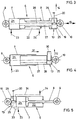
- the additional displacement drive 13 is formed by an additional hydraulic cylinder / piston unit integrated in the end of the piston rod 8 of the hydraulic cylinder / piston unit 6 which is adjacent to the articulation point 10, the cylinder of which is designated by 19 and the piston rod by 20.
- the articulation points of the hydraulic cylinder-piston unit 6 on the crane frame 2 or on the extension arm 3 are again designated 9 and 10.
- the working spaces of the hydraulic cylinder-piston assembly 6 are designated 21 and 22, hydraulic supply lines to these working spaces 21 and 22 being designated 23 and 24, respectively.
- the working space 22 of the hydraulic cylinder becomes Piston unit 6 acted upon accordingly and at the same time relieved the work space 21.
- the additional displacement drive 13 can always remain in its extended position after pivoting the articulation point 10 out of the dead center position, regardless of the pivoting position of the extension arm 3.
- plungers are used both for the hydraulic cylinder-piston unit 6 and for the additional displacement drive 13, these plungers 29 and 30 only being acted upon in the sense of their extension movement indicated by the arrows 31 and 32.
- This application takes place via the feed line 23 and via the connecting line 27 of the mutually connected working spaces 21 and 25 of the cylinder-piston units 6 and 13.
- the plunger 30 is extended a displacement or pivoting of the articulation point 10 from the dead center position, whereupon the plunger 29 is subsequently extended in the direction of the arrow 31 and causes the extension arm 3 to pivot.
- the working space 21 and thus the working space 25 are depressurized, whereupon the dead weight of the cantilever arm 3 which is in turn retracted into its fully pivoted position.
- hydraulic cylinder-piston units which are similar to those of the embodiment according to FIG. 3, are used both for the hydraulic cylinder-piston unit 6 and for the additional displacement drive 13. 3, however, it is provided in the embodiment shown in FIG. 5 to integrate the additional displacement drive 13 in the cylinder 7 in the region of the articulation point 10 of the hydraulic cylinder-piston unit 6. Similar to the embodiment according to FIG. 3, in the embodiment according to FIG. 5 the corresponding working spaces 21 and 25 or 22 and 26 of the hydraulic cylinder-piston units 6 and 13 are again coupled to one another via connecting lines, which are designated by 33 and 34 are. The hydraulic supply lines 23 and 24 connect to these connecting lines 33 and 34.
Applications Claiming Priority (2)
| Application Number | Priority Date | Filing Date | Title |
|---|---|---|---|
| AT534/95 | 1995-03-24 | ||
| AT53495A AT401925B (de) | 1995-03-24 | 1995-03-24 | Ladekran |
Publications (2)
| Publication Number | Publication Date |
|---|---|
| EP0733585A2 true EP0733585A2 (fr) | 1996-09-25 |
| EP0733585A3 EP0733585A3 (fr) | 1998-11-04 |
Family
ID=3493178
Family Applications (1)
| Application Number | Title | Priority Date | Filing Date |
|---|---|---|---|
| EP96890052A Withdrawn EP0733585A3 (fr) | 1995-03-24 | 1996-03-21 | Grue de chargement |
Country Status (3)
| Country | Link |
|---|---|
| EP (1) | EP0733585A3 (fr) |
| JP (1) | JPH08319093A (fr) |
| AT (1) | AT401925B (fr) |
Cited By (6)
| Publication number | Priority date | Publication date | Assignee | Title |
|---|---|---|---|---|
| EP1475345A1 (fr) * | 2003-05-09 | 2004-11-10 | Loglift Oy Ab | Procédé pour la commande d'une flèche de grue et dispositif pour la mise en oeuvre du procédé |
| EP2248753A1 (fr) * | 2009-05-07 | 2010-11-10 | EPSILON Kran GmbH. | Grue dotée d'une capacité à surmonter un point mort |
| WO2013004460A1 (fr) * | 2011-07-07 | 2013-01-10 | Putzmeister Engineering Gmbh | Mât distributeur pour des pompes à béton |
| DE102013222798A1 (de) * | 2013-11-08 | 2015-05-13 | Putzmeister Engineering Gmbh | Autobetonpumpe |
| CN108862056A (zh) * | 2018-04-28 | 2018-11-23 | 江苏科技大学 | 一种波浪补偿船用a型门架基座 |
| CN112897364A (zh) * | 2021-03-27 | 2021-06-04 | 国网上海市电力公司 | 一种用于gil通管吊装的工装小车 |
Families Citing this family (1)
| Publication number | Priority date | Publication date | Assignee | Title |
|---|---|---|---|---|
| DE4017467A1 (de) * | 1990-05-30 | 1991-12-05 | Henkel Kgaa | Verfahren zur herstellung von hellfarbigen alpha-sulfofettsaeurealkylester- alkalimetallsalzpasten |
Citations (6)
| Publication number | Priority date | Publication date | Assignee | Title |
|---|---|---|---|---|
| DE2505521A1 (de) * | 1974-02-21 | 1975-08-28 | Fiskars Ab Oy | Gelenkauslegerkran |
| AT355256B (de) * | 1976-12-10 | 1980-02-25 | Hiab Foco Ab | Vorrichtung an ladekraenen |
| FR2551042A1 (fr) * | 1983-08-29 | 1985-03-01 | Fiskars Ab Oy | Dispositif de repliement sous faible encombrement pour grue de camion ou autre vehicule |
| FR2600634A1 (fr) * | 1986-06-24 | 1987-12-31 | Guilhem Claire | Dispositif de commande d'articulation de deux bras d'un e ngin |
| DD255934A1 (de) * | 1986-11-11 | 1988-04-20 | Verlade Transportanlagen | Verfahrbares seitenladegeraet |
| WO1992004271A1 (fr) * | 1990-08-29 | 1992-03-19 | Hiab Ab | Grue |
-
1995
- 1995-03-24 AT AT53495A patent/AT401925B/de not_active IP Right Cessation
-
1996
- 1996-03-21 EP EP96890052A patent/EP0733585A3/fr not_active Withdrawn
- 1996-03-22 JP JP6613596A patent/JPH08319093A/ja active Pending
Patent Citations (6)
| Publication number | Priority date | Publication date | Assignee | Title |
|---|---|---|---|---|
| DE2505521A1 (de) * | 1974-02-21 | 1975-08-28 | Fiskars Ab Oy | Gelenkauslegerkran |
| AT355256B (de) * | 1976-12-10 | 1980-02-25 | Hiab Foco Ab | Vorrichtung an ladekraenen |
| FR2551042A1 (fr) * | 1983-08-29 | 1985-03-01 | Fiskars Ab Oy | Dispositif de repliement sous faible encombrement pour grue de camion ou autre vehicule |
| FR2600634A1 (fr) * | 1986-06-24 | 1987-12-31 | Guilhem Claire | Dispositif de commande d'articulation de deux bras d'un e ngin |
| DD255934A1 (de) * | 1986-11-11 | 1988-04-20 | Verlade Transportanlagen | Verfahrbares seitenladegeraet |
| WO1992004271A1 (fr) * | 1990-08-29 | 1992-03-19 | Hiab Ab | Grue |
Cited By (13)
| Publication number | Priority date | Publication date | Assignee | Title |
|---|---|---|---|---|
| EP1475345A1 (fr) * | 2003-05-09 | 2004-11-10 | Loglift Oy Ab | Procédé pour la commande d'une flèche de grue et dispositif pour la mise en oeuvre du procédé |
| EP2248753A1 (fr) * | 2009-05-07 | 2010-11-10 | EPSILON Kran GmbH. | Grue dotée d'une capacité à surmonter un point mort |
| RU2471702C2 (ru) * | 2009-05-07 | 2013-01-10 | Эпзилон Кран Гмбх. | Кран с преодолением мертвой точки |
| US8596474B2 (en) | 2009-05-07 | 2013-12-03 | Epsilon Kran Gmbh | Crane |
| RU2623379C2 (ru) * | 2011-07-07 | 2017-06-26 | Путцмайстер Инжиниринг Гмбх | Распределительная стрела для бетононасосов |
| WO2013004460A1 (fr) * | 2011-07-07 | 2013-01-10 | Putzmeister Engineering Gmbh | Mât distributeur pour des pompes à béton |
| JP2014524995A (ja) * | 2011-07-07 | 2014-09-25 | プッツマイスター エンジニアリング ゲーエムベーハー | コンクリートポンプのための分配ブーム |
| US9062465B2 (en) | 2011-07-07 | 2015-06-23 | Putzmeister Engineering Gmbh | Distributing boom for concrete pumps |
| DE102013222798A1 (de) * | 2013-11-08 | 2015-05-13 | Putzmeister Engineering Gmbh | Autobetonpumpe |
| CN108862056A (zh) * | 2018-04-28 | 2018-11-23 | 江苏科技大学 | 一种波浪补偿船用a型门架基座 |
| CN108862056B (zh) * | 2018-04-28 | 2023-11-21 | 江苏科技大学 | 一种波浪补偿船用a型门架基座 |
| CN112897364A (zh) * | 2021-03-27 | 2021-06-04 | 国网上海市电力公司 | 一种用于gil通管吊装的工装小车 |
| CN112897364B (zh) * | 2021-03-27 | 2023-08-08 | 国网上海市电力公司 | 一种用于gil通管吊装的工装小车 |
Also Published As
| Publication number | Publication date |
|---|---|
| JPH08319093A (ja) | 1996-12-03 |
| EP0733585A3 (fr) | 1998-11-04 |
| AT401925B (de) | 1996-12-27 |
| ATA53495A (de) | 1996-05-15 |
Similar Documents
| Publication | Publication Date | Title |
|---|---|---|
| EP0984895B1 (fr) | Grue a fleche telescopique | |
| DE2846470C2 (de) | Bewegliches Hubgerät | |
| EP1621682B1 (fr) | Appareil de transbordement. | |
| EP2139804B1 (fr) | Mécanisme de réglage pourvu d'un treuil à câble | |
| DE102009002613A1 (de) | Scherenhebebühne | |
| EP0182091B1 (fr) | Elévateur de puissance pour un dispositif de levage | |
| DE2601565A1 (de) | Vorrichtung zur steuerung und arretierung von stuetzauslegern eines fahrzeuges | |
| EP2799283B1 (fr) | Véhicule de transport de charge doté d'un conteneur interchangeable et d'un appareil de levage pour un conteneur interchangeable | |
| AT401925B (de) | Ladekran | |
| DE2346004A1 (de) | Teleskopausleger | |
| EP2895418B1 (fr) | Grue à tour | |
| DE2843587C2 (de) | Hebevorrichtung mit einer um eine lotrechte Achse drehbaren Plattform für einen Ausleger | |
| EP0830976B1 (fr) | Transporteur pour véhicules | |
| DE2648611C2 (fr) | ||
| EP0333066B1 (fr) | Engin de terrassement, notamment un chargeur | |
| DE60312913T2 (de) | Motorgetriebene Vorrichtung zum Aufrichten und Ausfahren des Mastes und zum Zusammenlegen des Auslegers eines Krans | |
| DE2340431A1 (de) | Hydraulische steuervorrichtung fuer einen kran | |
| DE3016157C2 (de) | Regalstapler für große Hubhöhen | |
| DE1101973B (de) | Lastentransportgeraet mit Schreitfuessen | |
| DE2834480A1 (de) | Parallelfuehr-einrichtung fuer ein fahrzeug-frontlader-arbeitsgeraet | |
| EP0006871B1 (fr) | Dispositif de levage et d'abaissement pour basculer une plateforme de chargement, notamment pour camions et remorques | |
| EP0706931B1 (fr) | Dispositif pour déplacer en rotation une première partie d'un panneau repliable, par rapport à une deuxième partie | |
| DE1756407C3 (de) | Sicherheitsvorrichtung für einen hydraulischen Auslegerkran | |
| DE10104310B4 (de) | Fahrzeugkran mit Teleskopausleger | |
| DE4106885C2 (fr) |
Legal Events
| Date | Code | Title | Description |
|---|---|---|---|
| PUAI | Public reference made under article 153(3) epc to a published international application that has entered the european phase |
Free format text: ORIGINAL CODE: 0009012 |
|
| AK | Designated contracting states |
Kind code of ref document: A2 Designated state(s): BE CH DE DK ES FI FR GB GR IE IT LI LU MC NL PT SE |
|
| AX | Request for extension of the european patent |
Free format text: LT PAYMENT 960325;SI PAYMENT 960325 |
|
| RAX | Requested extension states of the european patent have changed |
Free format text: LT PAYMENT 960325;SI PAYMENT 960325 |
|
| PUAL | Search report despatched |
Free format text: ORIGINAL CODE: 0009013 |
|
| AK | Designated contracting states |
Kind code of ref document: A3 Designated state(s): BE CH DE DK ES FI FR GB GR IE IT LI LU MC NL PT SE |
|
| AX | Request for extension of the european patent |
Free format text: LT PAYMENT 960325;SI PAYMENT 960325 |
|
| 17P | Request for examination filed |
Effective date: 19981110 |
|
| GRAP | Despatch of communication of intention to grant a patent |
Free format text: ORIGINAL CODE: EPIDOSNIGR1 |
|
| GRAP | Despatch of communication of intention to grant a patent |
Free format text: ORIGINAL CODE: EPIDOSNIGR1 |
|
| STAA | Information on the status of an ep patent application or granted ep patent |
Free format text: STATUS: THE APPLICATION IS DEEMED TO BE WITHDRAWN |
|
| 18D | Application deemed to be withdrawn |
Effective date: 20040330 |