EP0732714B1 - Elektrischer Schalter, insbesondere für Elektrohandwerkzeuge - Google Patents
Elektrischer Schalter, insbesondere für Elektrohandwerkzeuge Download PDFInfo
- Publication number
- EP0732714B1 EP0732714B1 EP96102959A EP96102959A EP0732714B1 EP 0732714 B1 EP0732714 B1 EP 0732714B1 EP 96102959 A EP96102959 A EP 96102959A EP 96102959 A EP96102959 A EP 96102959A EP 0732714 B1 EP0732714 B1 EP 0732714B1
- Authority
- EP
- European Patent Office
- Prior art keywords
- housing
- heat sink
- carrier part
- electric switch
- switch according
- Prior art date
- Legal status (The legal status is an assumption and is not a legal conclusion. Google has not performed a legal analysis and makes no representation as to the accuracy of the status listed.)
- Expired - Lifetime
Links
- 238000007789 sealing Methods 0.000 description 35
- 239000004065 semiconductor Substances 0.000 description 17
- 238000001816 cooling Methods 0.000 description 13
- 238000012546 transfer Methods 0.000 description 7
- 238000013459 approach Methods 0.000 description 6
- 238000004519 manufacturing process Methods 0.000 description 6
- 239000000428 dust Substances 0.000 description 5
- 210000002445 nipple Anatomy 0.000 description 3
- RYGMFSIKBFXOCR-UHFFFAOYSA-N Copper Chemical compound [Cu] RYGMFSIKBFXOCR-UHFFFAOYSA-N 0.000 description 2
- 229910052782 aluminium Inorganic materials 0.000 description 2
- XAGFODPZIPBFFR-UHFFFAOYSA-N aluminium Chemical compound [Al] XAGFODPZIPBFFR-UHFFFAOYSA-N 0.000 description 2
- 230000006835 compression Effects 0.000 description 2
- 238000007906 compression Methods 0.000 description 2
- 229910052802 copper Inorganic materials 0.000 description 2
- 239000010949 copper Substances 0.000 description 2
- 238000013461 design Methods 0.000 description 2
- 238000001746 injection moulding Methods 0.000 description 2
- 239000000463 material Substances 0.000 description 2
- 229910052751 metal Inorganic materials 0.000 description 2
- 239000002184 metal Substances 0.000 description 2
- 230000035515 penetration Effects 0.000 description 2
- 239000004033 plastic Substances 0.000 description 2
- 238000003825 pressing Methods 0.000 description 2
- 229920001169 thermoplastic Polymers 0.000 description 2
- 238000012549 training Methods 0.000 description 2
- 239000004952 Polyamide Substances 0.000 description 1
- RRLHMJHRFMHVNM-BQVXCWBNSA-N [(2s,3r,6r)-6-[5-[5-hydroxy-3-(4-hydroxyphenyl)-4-oxochromen-7-yl]oxypentoxy]-2-methyl-3,6-dihydro-2h-pyran-3-yl] acetate Chemical compound C1=C[C@@H](OC(C)=O)[C@H](C)O[C@H]1OCCCCCOC1=CC(O)=C2C(=O)C(C=3C=CC(O)=CC=3)=COC2=C1 RRLHMJHRFMHVNM-BQVXCWBNSA-N 0.000 description 1
- 238000005352 clarification Methods 0.000 description 1
- 230000001276 controlling effect Effects 0.000 description 1
- 230000001419 dependent effect Effects 0.000 description 1
- 238000011161 development Methods 0.000 description 1
- 239000003365 glass fiber Substances 0.000 description 1
- 238000007373 indentation Methods 0.000 description 1
- 230000000149 penetrating effect Effects 0.000 description 1
- 229920002647 polyamide Polymers 0.000 description 1
- 230000002028 premature Effects 0.000 description 1
- 230000001105 regulatory effect Effects 0.000 description 1
- 239000012815 thermoplastic material Substances 0.000 description 1
- 239000004416 thermosoftening plastic Substances 0.000 description 1
- 238000010792 warming Methods 0.000 description 1
Images


Classifications
-
- H—ELECTRICITY
- H01—ELECTRIC ELEMENTS
- H01H—ELECTRIC SWITCHES; RELAYS; SELECTORS; EMERGENCY PROTECTIVE DEVICES
- H01H9/00—Details of switching devices, not covered by groups H01H1/00 - H01H7/00
- H01H9/52—Cooling of switch parts
-
- H—ELECTRICITY
- H01—ELECTRIC ELEMENTS
- H01H—ELECTRIC SWITCHES; RELAYS; SELECTORS; EMERGENCY PROTECTIVE DEVICES
- H01H9/00—Details of switching devices, not covered by groups H01H1/00 - H01H7/00
- H01H9/02—Bases, casings, or covers
- H01H9/06—Casing of switch constituted by a handle serving a purpose other than the actuation of the switch, e.g. by the handle of a vacuum cleaner
-
- H—ELECTRICITY
- H01—ELECTRIC ELEMENTS
- H01H—ELECTRIC SWITCHES; RELAYS; SELECTORS; EMERGENCY PROTECTIVE DEVICES
- H01H9/00—Details of switching devices, not covered by groups H01H1/00 - H01H7/00
- H01H9/02—Bases, casings, or covers
- H01H9/06—Casing of switch constituted by a handle serving a purpose other than the actuation of the switch, e.g. by the handle of a vacuum cleaner
- H01H2009/065—Battery operated hand tools in which the battery and the switch are directly connected
-
- H—ELECTRICITY
- H01—ELECTRIC ELEMENTS
- H01H—ELECTRIC SWITCHES; RELAYS; SELECTORS; EMERGENCY PROTECTIVE DEVICES
- H01H9/00—Details of switching devices, not covered by groups H01H1/00 - H01H7/00
- H01H9/02—Bases, casings, or covers
- H01H9/04—Dustproof, splashproof, drip-proof, waterproof, or flameproof casings
-
- H—ELECTRICITY
- H01—ELECTRIC ELEMENTS
- H01H—ELECTRIC SWITCHES; RELAYS; SELECTORS; EMERGENCY PROTECTIVE DEVICES
- H01H9/00—Details of switching devices, not covered by groups H01H1/00 - H01H7/00
- H01H9/02—Bases, casings, or covers
- H01H9/06—Casing of switch constituted by a handle serving a purpose other than the actuation of the switch, e.g. by the handle of a vacuum cleaner
- H01H9/061—Casing of switch constituted by a handle serving a purpose other than the actuation of the switch, e.g. by the handle of a vacuum cleaner enclosing a continuously variable impedance
-
- H—ELECTRICITY
- H01—ELECTRIC ELEMENTS
- H01H—ELECTRIC SWITCHES; RELAYS; SELECTORS; EMERGENCY PROTECTIVE DEVICES
- H01H9/00—Details of switching devices, not covered by groups H01H1/00 - H01H7/00
- H01H9/02—Bases, casings, or covers
- H01H9/06—Casing of switch constituted by a handle serving a purpose other than the actuation of the switch, e.g. by the handle of a vacuum cleaner
- H01H9/063—Casing of switch constituted by a handle serving a purpose other than the actuation of the switch, e.g. by the handle of a vacuum cleaner enclosing a reversing switch
Definitions
- the invention relates to an electrical switch according to the Preamble of claim 1.
- the switch has a housing for Inclusion of two contact systems, one movable Actuator on the switch contacts of the two Contact systems acts, and one in the housing Control electronics and an associated power transistor for changing the speed of the electric motor.
- To derive the Heat loss is in a wall opening in the housing arranged power transistor via a cooling vane with a located on the outside of the housing Heat sink covering the wall opening in a heat-conducting Connection.
- the connecting bolt requires an internal thread for mounting the screw for the heat sink.
- the connecting bolt is a manufacturing-related part that also deals with the Bearing plate must be soldered or welded. Another additional operation is during assembly for that It is necessary to screw the heat sink. So the assembly is the known switch complex and therefore expensive.
- Another disadvantage is that when mounting the heat sink there is no guarantee that the cooling plume of the Power transistor is applied to the heat sink. In this case there may be poor heat transfer between the Power transistor and the heat sink exist so that the Incomplete dissipation of heat loss from the power transistor becomes. As a result, the switch may be inadmissible Warming will be destroyed.
- the wall opening is with this switch with screwed on heat sink closed to the outside.
- Electric hand tools however, often under extreme Operating conditions, it is not exclude that dust and dirt between the heat sink and the housing wall at the wall opening into the interior of the housing can penetrate, especially if the screw through Vibrations of the electric hand tool loosen. As a result the risk of premature failure of the switch.
- the invention is based, such to design electrical switches such that the assembly is simplified and improved. Furthermore, the protection against Penetration of dust and dirt in the housing improved become.
- the carrier part is as in one piece from one located inside the switch Bearing part on which the switch contact of a contact system is articulated, outgoing current-carrying and heat-conducting Connection bridge formed.
- a carrier part is easy and inexpensive to manufacture as a stamped part.
- the connecting web penetrates the cooling vane on Power semiconductors and an opening in the heat sink.
- the Connecting web can on its side facing the heat sink Be conical end so that the heat sink at the Assembly only by means of its opening on the Connecting web is pressed. So that the heat sink held non-positively on the connecting web.
- the conical end the connecting web also offers a kind of Tolerance compensation, so that the cooling vane of the Power semiconductor during assembly always in proper Attachment to the heat sink for training a good one Heat transfer comes. It is also possible that the opening of the heat sink penetrating part of the connecting web twist, so that a kind of positive connection through the entanglement is achieved between the connecting web and the heat sink. It is also possible to connect the connecting web in the opening of the Heat sink to form a positive connection caulk or stamp.
- the sealing edge or the sealing lip can be easily Way in one step in the manufacture of the housing of the switch with injection molding, whereby preferably the same thermoplastic material for the Sealing edge or the sealing lip as used for the housing becomes.
- the sealing lip has a lower one Thickness like the housing wall, with the sealing lip being about U-shaped, resilient approach can be designed.
- a further simplification of the assembly of the switch lets achieve it by looking at the outside of the case, especially located in the vicinity of the sealing edge or the sealing lip Fixing and / or locking elements are arranged on the Heatsink is snapped on.
- the heat sink can be made of copper, Aluminum or the like exist and on its surface be structured.
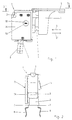
- the Switch 1 for speed regulation of Electric motors, in particular in electric hand tools an electric motor, especially in cordless power tools with a DC motor like For example, drills, electric screwdrivers or the like Use is shown schematically in Fig. 1.
- the Switch 1 has a housing 2, which consists of a thermoplastic, especially one glass fiber reinforced polyamide.
- On the housing 2 is a formed as a pusher, movable actuator 3 with an attached, leading into the interior of the switch 1 Actuating plunger 4 arranged.
- the actuator 3 can manually in the direction of arrow 5 against one in FIG. 3 shown compression spring 53 are moved so that it after Let go back to the starting position according to the Arrow 5 'returns. With the help of the actuator 3 is the electric hand tool switched on and depending on the position of the actuator 3, the speed of the electric motor regulated.
- the switch 1 In the housing 2 of the switch 1 is a switch for the direction of rotation of the electric motor with a in Fig. 3rd visible contact system 13 integrated, the Contact system 13 as a polarity switch for the electric motor is formed and actuated via an actuating lever 6 is.
- the operating lever 6 is in two switching positions movable, namely in a first for clockwise rotation and in a second for the counterclockwise rotation of the electric motor, wherein according to the respective switching position of the Actuating lever 6 the circuit to the electric motor so is switched that the electric motor runs right or left.
- hook element 42 On the operating lever 6 is in the interior of the housing 2 designed in one piece with the actuating lever 6 Arranged hook element 42, which in a corresponding Setting 43 for generating a pressure point at the Switching and a detent in the respective Switch positions engages. Both the hook element 42 and the backdrop 43 are made of plastic.
- connection clips 8 are integrally connected to the connections 7 by the Connections 7 with the connection clips 8 as appropriate curved stamped part are designed.
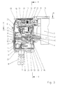
- Fig. 3 goes inside the Housing 2 from the first terminal 7 in one piece Contact rail 9 from that to two located in the housing 2 Contact systems 11, 12 leads to which the actuator 3rd acts by means of a cam control.
- Cam controls are located on a shoulder 15 of the Actuating plunger 4 cams 24, 25, the cam 24 in Fig. 3 is actually hidden and therefore partially is shown broken.
- the contact system 12 is on a bearing plate 32, of which in turn one Contact path 54 to a contact of the contact system 13 of the Switch for the direction of rotation of the electric motor runs.
- Another contact rail 10 goes from the second connection 7 from that through the housing 2 to the other contact of the Contact system 13 leads.
- This switch is located then finally connections 14 at the top of the Housing 2 for connection to supply lines for the Electric motor, as again shown in Fig. 2.
- the contact rail 10 designed so that this and a 32 on the bearing plate attached contact arm 44 a contact point 45 for a Actuating plunger 4 arranged contact bridge 46 form.
- the actuating member 3 is in the position in FIG. 3 shown, unactuated position, so closes the Contact bridge 46 the electric motor via the contact point 45 short and thus causes the electric motor to brake.
- the contact systems 11, 12 each consist of one with the Contact rail 9 connected fixed contact 16, 17th and one that can be rotated in a cutting edge bearing 18, 19 Switching contact 20, 21, which by means of a tension spring 22, 23 in A force is applied to the closing direction.
- the switch contacts 20, 21 when not actuated Actuator 3 in the positively open position held by the cams 24, 25 on one end of the Switching contact 20, 21 acts, whereby the contact connection between the other end of the switch contact 20, 21 and the Fixed contact 16, 17 is open.
- the actuator 3 1 in the direction of arrow 5 is over the geometry of the respective cam 24, 25 the position of the Determines actuator 3, in which the contact system 11, 12 closes or opens.
- On a certain one Operating position of the actuator 3 gives the cam 24, 25 one end of the switching contact 20, 21 free, whereby the tension spring 22, 23 the other end of the switching contact 20, 21 pulls to the fixed contact 16, 17, so that the electrical Connection is then closed.
- the cams 24, 25 switches when actuator 3 moves in the direction of arrow 5 1, the contact system 11, which the Power supply from the battery for one in the housing 2 located control electronics 26 and an associated Power semiconductor 28 for changing the speed of the Electric motor is turned on.
- the control electronics 26 is, as can be seen in FIG. 4, on a printed circuit board 27 arranged.
- To regulate the speed is in the Interior of the housing 2 in a receptacle 50 on the approach 15 of the Actuating plunger 4 is a grinder 51.
- This grinder 51 one end slides on one on the circuit board 27 Resistance track 52 located, with which the grinder 51 and the resistance track 52 form a potentiometer.
- the grinder 51 becomes linear moved on the resistance track 52 and thus the position of the Potentiometers changed.
- the position of the Potentiometers corresponding electrical resistance, the thus in correlation to the respective position of the Actuator 3 is used as a setpoint for the Speed setting and control of the electric motor by means of the control electronics 26 located on the printed circuit board 27. According to this setpoint, the electric motor is switched off Control electronics 26 through the power semiconductor 28 through a pulse width modulation controlled.
- Power semiconductor 28 can be a power transistor, for example a MOS-FET can be used. Circuit arrangements for such control electronics 26 are known so that it is not necessary to elaborate on this enter into.
- the power semiconductor 28 with its connections 29 also arranged on the circuit board 27 and has one Cooling vane 30, which is a further connection of the Power semiconductor 28 for the motor current to be controlled a carrier part 31 designed as a connecting web with the Bearing plate 32 is electrically connected. from Bearing plate 32 guides the contact track 54 shown in FIG. 3, as already mentioned, continue to the contact system 13 of the Switch for the direction of rotation of the electric motor.
- a Free-wheeling diode 47 is used to protect the control electronics 26 between the bearing plate 32 and the contact rail 10 articulated or fastened.
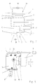
- FIG. 7 Circuit arrangement for the electrical switch 1 represented schematically.
- a battery 56 is with the Connections 7 of the switch 1 connected.
- the battery 56 is used as an energy source for an electric motor 57, which in turn the connections 14 of the switch 1 is connected.
- the electric motor 57 On the Switch 1, the electric motor 57, as already described, according to the position of the actuator 3 and the Actuating lever 6 controlled.
- the Wall opening 33 is with one on the outside of the Switch housing 2 located heat sink 34 covered on a circumferential around the wall opening 33, such as the 5, essentially rigid sealing edge 37 dust-tight by means of a certain contact pressure.
- the Sealing edge 37 consists of the same material as the housing 2 and is molded onto the housing 2 in one piece. It continues the heat sink 34 by contacting the cooling vane 30 thermally conductive with the power semiconductor 28 in connection.
- the bearing plate 32 is over the current-carrying and heat-conducting carrier part 31, which the Cooling vane 30 of the power semiconductor 28 at an opening 59 interspersed, connected to the heat sink 34.
- the carrier part 31 is a connecting web corresponding to the Fig. 4 in one piece from that designed as a stamped part Bearing plate 32 bent and thus on the bearing plate 32 inside the housing 2 attached.
- the one made of metal, for example Copper, aluminum or the like existing heat sink 34 is on the outside of the housing 2 through the carrier part 31 held.
- the carrier part 31 is designed such that it from inside the housing 2 through the wall opening 33 protrudes and at least extends to the heat sink 34, where the Heatsink 34 non-positively and / or positively on Carrier part 31 is arranged.
- the heat sink 34 without additional fasteners, in particular without Screws, rivets or the like immovably on the carrier part 31 kept, both by a certain contact pressure the carrier part 31 as well as on the cooling vane 30 a good one Heat transfer is ensured.
- its surface can be used to enlarge the Heat transfer surface can still be structured, for example by incorporating elevations and in-depths.
- the carrier part 31 is approximately vertical in the present case arranged to the heat sink 34 and extends slightly over the Heatsink 34, which is the outside of the housing 2nd assigned part 58 of the carrier part 31 to the heat sink 34 an opening 48 passes through.
- a first embodiment is to hold the heat sink 34 part 58 of the Carrier part 31, which is located in the area of the heat sink 34 is conical, as can be seen in particular in FIG. 6 is.
- the heat sink 34 is by means of its Opening 48 on the carrier part 31 on the conical part 58 as far pressed on until the heat sink 34 abuts the sealing edge 37. A frictional connection between the heat sink 34 and the Carrier part 31 made.
- the assembly can expediently of the heat sink 34 so that the conical Side flanks of part 58 in the area surrounding opening 48 Cut the material of the heat sink 34, causing the Adhesion is further increased.
- the power semiconductor 28 is thereby pressed into its end position by means of the heat sink 34, so that a secure and flat contact of the cooling vane 30 on the heat sink 34 and thus a good heat transfer are guaranteed.
- By pressing the heat sink 34 to the system on Sealing edge 37 are advantageously by the conical Part 58 Manufacturing tolerances while maintaining the adhesion between the carrier part 31 and the heat sink 34 balanced, so that always a safe dust tightness the switch 1 is guaranteed.
- part 58 is at Carrier part 31 is essentially rectangular.
- the heat sink 34 is placed on the carrier part 31 with the opening 48 put on, the part 58 protrudes.
- the opening 48 from a recess 55 in the heat sink 34 surrounded on its outer surface.
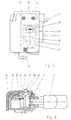
- the protruding part 58 of the carrier part 31 is then in the recess 55 by twisting or the like with an entanglement 49 provided, as can be seen in Fig. 8.
- the heat sink 34 can also Carrier part 31 be caulked or stamped.
- the sealing edge formed as a sealing lip 60 is as shown in Fig. 9.
- the sealing lip 60 is for Outside of the housing 2 directed.
- the outside of the Housing 2 associated end of the sealing lip 60 is in positive connection with the heat sink 34 by the Sealing lip 60 rests elastically on the heat sink.
- Sealing lip 60 also positively with the heat sink 34 in Connect.
- the outside of the Housing 2 associated end of the sealing lip 60 for example in a circumferential, corresponding groove 38 on Heatsink 34 a.
- the sealing lip 60 can be made of the same thermoplastic Plastic like the housing wall 39 and are made in one piece with be connected to the housing 2.
- the sealing lip 60 can be particularly easy to manufacture if they are in the making the housing wall 39 is also molded in one operation.
- the sealing lip is used to achieve the necessary elasticity 60 with a smaller thickness than the housing wall 39 designed.
- the sealing lip 60 is an elastic, resilient approach 41 formed, which has approximately a U-shape has a recess 40 to the housing wall 39.
- the Approach 41 stands at an angle from the surface of the housing wall 39 starting at an angle of approximately 50 to 90 degrees can act.
Landscapes
- Rotary Switch, Piano Key Switch, And Lever Switch (AREA)
- Push-Button Switches (AREA)
Description
- Fig. 1
- einen elektrischen Schalter für ein Elektrohandwerkzeug in Seitenansicht,
- Fig. 2
- eine Frontansicht des elektrischen Schalters in Richtung des Pfeils 5 aus Fig. 1,
- Fig. 3
- einen Längsschnitt entlang der Linie 3-3 aus Fig. 1,
- Fig. 4
- einen Längsschnitt entlang der Linie 4-4 aus Fig. 3,
- Fig. 5
- eine Seitenansicht wie in Fig. 1, wobei der an sich nicht sichtbare Wanddurchbruch gestrichelt eingezeichnet ist,
- Fig. 6
- einen Schnitt entlang der Linie 6-6 aus Fig. 3,
- Fig. 7
- schematisch eine Schaltungsanordnung für den elektrischen Schalter,
- Fig. 8
- einen elektrischen Schalter wie in Fig. 1 in einer weiteren Ausführungsform und
- Fig. 9
- einen Schnitt wie in Fig. 6 in nochmals einer weiteren Ausführungsform.
- 1:
- Schalter
- 2:
- Gehäuse
- 3:
- Betätigungsorqan
- 4:
- Betätigungsstößel
- 5, 5':
- Pfeil (für Bewegung des Betätigungsorgans)
- 6:
- Betätigungshebel
- 7:
- Anschluß
- 8:
- Anschlußklammer
- 9, 10:
- Kontaktschiene
- 11, 12:
- Kontaktsystem
- 13:
- Kontaktsystem (Umschalter)
- 14:
- Anschluß
- 15:
- Ansatz (am Betätigungsstößel)
- 16, 17:
- Festkontakt
- 18, 19:
- Schneidenlager
- 20, 21:
- Schaltkontakt
- 22, 23:
- Zugfeder
- 24, 25:
- Nocken
- 26:
- Steuerelektronik
- 27:
- Leiterplatte
- 28:
- Leistungshalbleiter
- 29:
- Anschluß (Leistungshalbleiter)
- 30:
- Kühlfahne
- 31:
- Trägerteil
- 32:
- Lagerblech
- 33:
- Wanddurchbruch
- 34:
- Kühlkörper
- 35:
- Rasthaken
- 36:
- Ausnehmung (Kühlkörper)
- 37:
- Dichtrand
- 38:
- Nut (am Kühlkörper)
- 39:
- Gehäusewand
- 40:
- Vertiefung
- 41:
- Ansatz
- 42:
- Hakenelement (Umschalter)
- 43:
- Kulisse
- 44:
- Kontaktarm
- 45:
- Kontaktstelle
- 46:
- Kontaktbrücke
- 47:
- Freilaufdiode
- 48:
- Öffnung (im Kühlkörper)
- 49:
- Verschränkung
- 50:
- Aufnahme
- 51:
- Schleifer
- 52:
- Widerstandsbahn
- 53:
- Druckfeder
- 54:
- Kontaktbahn
- 55:
- Vertiefung (im Kühlkörper)
- 56:
- Akku
- 57:
- Elektromotor
- 58:
- Teil des Trägerteils (an der Außenseite)
- 59:
- Öffnung (in Kühlfahne)
- 60:
- Dichtlippe
- 61:
- Nippel
Claims (11)
- Elektrischer Schalter für ein Elektrohandwerkzeug mit einem Elektromotor (57), insbesondere für ein Akku-Elektrowerkzeug mit einem Gleichstrommotor, mit einem Gehäuse (2) zur Aufnahme eines Kontaktsystems (11, 12), mit einem bewegbaren Betätigungsorgan (3), das auf wenigstens einen Schaltkontakt (20, 21) des Kontaktsystems (11, 12) einwirkt, und mit einer Steuerelektronik (26) sowie einem zugehörigen Leistungshalbleiter (28) zur Drehzahlveränderung des Elektromotors (57), wobei der Leistungshalbleiter (28) über ein stromführendes und wärmeleitendes Trägerteil (31) mit einem im Gehäuse (2) befindlichen Bauteil, wie dem Kontaktsystem (12), in Verbindung steht und wobei der Leistungshalbleiter (28) weiter mit einem an der Außenseite des Gehäuses (2) befindlichen Kühlkörper (34) in wärmeleitender Verbindung steht, dadurch gekennzeichnet, daß das Trägerteil (31) durch einen Wanddurchbruch (33) des Gehäuses (2) wenigstens bis zum Kühlkörper (34) reicht und daß der Kühlkörper (34) kraft- und/oder formschlüssig direkt am Trägerteil (31) gehalten ist.
- Elektrischer Schalter nach Anspruch 1, dadurch gekennzeichnet, daß der an seiner Oberfläche gegebenenfalls strukturierte Kühlkörper (34) aus Metall, wie Kupfer, Aluminium o. dgl. besteht, daß der Leistungshalbleiter (28) vorzugsweise im Wanddurchbruch (33) des Gehäuses (2) angeordnet ist, und daß weiter vorzugsweise der Wanddurchbruch (33) des Gehäuses (2) mit dem Kühlkörper (34) abgedeckt ist, wobei der Kühlkörper (34) insbesondere ohne zusätzliche Befestigungsmittel am Trägerteil (31) angeordnet ist.
- Elektrischer Schalter nach Anspruch 1 oder 2, dadurch gekennzeichnet, daß der Schaltkontakt (21) des Kontaktsystems (12) und gegebenenfalls eine Freilaufdiode (47) zum Schutz der Steuerelektronik (26) an einem gemeinsamen Lagerblech (32) angelenkt bzw. befestigt sind, wobei das Lagerblech (32) über einen das Trägerteil (31) bildenden Verbindungssteg, der insbesondere einstückig von dem als Stanzteil ausgebildeten Lagerblech (32) abgebogen ist, mit dem Leistungshalbleiter (28) und dem Kühlkörper (34) verbunden ist, indem der Verbindungssteg gegebenenfalls eine am Leistungshalbleiter (28) angeordnete Kühlfahne (30) sowie eine im Kühlkörper (34) befindliche Öffnung (48) durchsetzt.
- Elektrischer Schalter nach Anspruch 1, 2 oder 3, dadurch gekennzeichnet, daß das Trägerteil (31) ungefähr senkrecht zum Kühlkörper (34) angeordnet ist, wobei vorzugsweise der der Außenseite des Gehäuses (2) zugeordnete Teil (58) des Trägerteils (31) die Öffnung (48) im Kühlkörper (34) durchsetzt, die insbesondere von einer Vertiefung (55) umgeben ist.
- Elektrischer Schalter nach Anspruch 4, dadurch gekennzeichnet, daß der Teil (58) des Trägerteils (31) im Bereich des Kühlkörpers (34) konisch ausgebildet ist, so daß der Kühlkörper (34) mittels seiner Öffnung (48) auf das Trägerteil (31) aufgepreßt ist, oder daß das Trägerteil (31) durch eine Verdrehung o. dgl., gegebenenfalls in der die Öffnung (48) umgebenden Vertiefung (55) im Kühlkörper (34), mit einer Verschränkung (49) versehen ist, oder daß der Kühlkörper (34) im Bereich der Öffnung (48) mit dem Trägerteil (31) verstemmt, verprägt o. dgl. ist.
- Elektrischer Schalter nach einem der Ansprüche 1 bis 5, dadurch gekennzeichnet, daß der Rand des Wanddurchbruchs (33) mit einem ringsumlaufenden, einstückig mit dem Gehäuse (2) verbundenen und zur Außenseite des Gehäuses (2) gerichteten Dichtrand (37) oder einer ebensolchen Dichtlippe (60) versehen ist, wobei das der Außenseite des Gehäuses (2) zugeordnete Ende des Dichtrandes (37) oder der Dichtlippe (60) in kraft- und/oder formschlüssiger Verbindung, insbesondere unter einem Anpreßdruck, mit dem Kühlkörper (34) steht.
- Elektrischer Schalter nach Anspruch 6, dadurch gekennzeichnet, daß das Gehäuse (2) aus einem thermoplastischen Kunststoff, insbesondere einem glasfaserverstärkten Polyamid besteht, wobei der Dichtrand (37) oder die Dichtlippe (60) vorzugsweise aus demselben thermoplastischen Kunststoff wie die Gehäusewand (39) mit einer gegenüber der Gehäusewand (39) geringeren Dicke besteht und der Dichtrand (37) oder die Dichtlippe (60) weiter vorzugsweise bei der Herstellung der Gehäusewand (39) mit angespritzt wird.
- Elektrischer Schalter nach Anspruch 6 oder 7, dadurch gekennzeichnet, daß die Dichtlippe (60) als elastischer, federnder Ansatz (41), vorzugsweise ungefähr in U-Form mit einer Vertiefung (40) zur Gehäusewand (39) ausgebildet ist, wobei der Ansatz (41) von der Oberfläche der Gehäusewand (39), insbesondere mit einem Winkel von ungefähr 50 bis 90 Grad absteht und wobei die Dichtlippe (37) vorzugsweise in eine korrespondierende Nut (38) am Kühlkörper (34) eingreift.
- Elektrischer Schalter nach einem der Ansprüche 1 bis 8, dadurch gekennzeichnet, daß an der Außenseite des Gehäuses (2) Fixier- und/oder Rastelemente, wie Rasthaken (35), Nippel (61), Nocken, Zapfen o. dgl., insbesondere in der Nähe des Dichtrandes (37) oder der Dichtlippe (60) angeordnet sind, die gegebenenfalls in der Art von Schnappverbindungen in Ausnehmungen (36) am Kühlkörper (34) zu dessen Fixierung am Gehäuse (2) einrasten.
- Elektrischer Schalter nach einem der Ansprüche 1 bis 9, dadurch gekennzeichnet, daß die in das Gehäuse (2) hineinführenden Anschlüsse (7) für die Stromzuführung an der Außenseite des Gehäuses (2) mit Anschlußklammern (8), insbesondere zum Anschluß an einen Akku (56) versehen sind, wobei die Anschlußklammern (8) vorzugsweise einstückig mit den Anschlüssen (7) verbunden sind, indem die Anschlüsse (7) mit den Anschlußklammern (8) als entsprechend gebogenes Stanzteil ausgestaltet sind.
- Elektrischer Schalter nach einem der Ansprüche 1 bis 10, dadurch gekennzeichnet, daß im Gehäuse (2) ein mittels eines Betätigungshebels (6) betätigbarer Umschalter für die Drehrichtung des Elektromotors (57) integriert ist, wobei am Betätigungshebel (6) im Inneren des Gehäuses (2) ein insbesondere einstückig mit dem Betätigungshebel (6) ausgestaltetes Hakenelement (42) angeordnet ist, das zur Erzeugung eines Druckpunktes sowie von Raststellungen bei der Umschaltung in eine korrespondierende Kulisse (43) eingreift und wobei das Hakenelement (42) und die Kulisse (43) vorzugsweise aus Kunststoff bestehen.
Applications Claiming Priority (2)
| Application Number | Priority Date | Filing Date | Title |
|---|---|---|---|
| DE19508925 | 1995-03-13 | ||
| DE19508925A DE19508925A1 (de) | 1995-03-13 | 1995-03-13 | Elektrischer Schalter, insbesondere für Elektrohandwerkzeuge |
Publications (3)
| Publication Number | Publication Date |
|---|---|
| EP0732714A2 EP0732714A2 (de) | 1996-09-18 |
| EP0732714A3 EP0732714A3 (de) | 1997-10-22 |
| EP0732714B1 true EP0732714B1 (de) | 2002-02-06 |
Family
ID=7756478
Family Applications (1)
| Application Number | Title | Priority Date | Filing Date |
|---|---|---|---|
| EP96102959A Expired - Lifetime EP0732714B1 (de) | 1995-03-13 | 1996-02-28 | Elektrischer Schalter, insbesondere für Elektrohandwerkzeuge |
Country Status (3)
| Country | Link |
|---|---|
| US (1) | US5798584A (de) |
| EP (1) | EP0732714B1 (de) |
| DE (2) | DE19508925A1 (de) |
Families Citing this family (38)
| Publication number | Priority date | Publication date | Assignee | Title |
|---|---|---|---|---|
| DE19635102B4 (de) * | 1996-08-30 | 2006-01-19 | Marquardt Gmbh | Elektrischer Schalter |
| DE19651872A1 (de) * | 1996-12-13 | 1998-06-18 | Marquardt Gmbh | Elektrischer Schalter |
| DE19831458B4 (de) * | 1997-07-24 | 2009-04-02 | Marquardt Gmbh | Elektrischer Schalter, insbesondere für ein Akku-Elektrowerkzeug |
| US6536536B1 (en) * | 1999-04-29 | 2003-03-25 | Stephen F. Gass | Power tools |
| US6448676B1 (en) | 1999-05-18 | 2002-09-10 | Siemens Automotive Inc. | Pulse width modulated engine cooling fan motor with integrated MOSFET |
| US7666192B2 (en) * | 2001-02-16 | 2010-02-23 | Kci Licensing, Inc. | Skin grafting devices and methods |
| US6552904B2 (en) | 2001-08-13 | 2003-04-22 | Black & Decker Inc. | Power tool with heat sink assembly |
| US6737598B1 (en) | 2002-12-11 | 2004-05-18 | Tyco Electronics Canada, Ltd. | Electrical switch with limited contact arcing |
| US7004357B2 (en) * | 2003-05-15 | 2006-02-28 | Alemite, Llc | Grease gun |
| US20050153596A1 (en) * | 2004-01-13 | 2005-07-14 | Vanwambeke Weston | Power tool battery connector |
| US7249695B2 (en) * | 2004-10-28 | 2007-07-31 | Alemite, Llc | Grease gun |
| DE102005001748B4 (de) | 2005-01-14 | 2019-01-24 | Marquardt Gmbh | Elektrischer Schalter und Elektrohandwerkzeug mit einem solchen Schalter |
| US7705260B2 (en) | 2005-04-18 | 2010-04-27 | Xinsheng Xu | Switch assembly |
| CN102324334A (zh) * | 2005-05-11 | 2012-01-18 | 布莱克和戴克公司 | 用于电动工具的万用端子系统 |
| US20070229008A1 (en) * | 2006-03-31 | 2007-10-04 | Heiko Roehm | Hand power tool |
| DE102007037125A1 (de) | 2006-08-10 | 2008-04-03 | Marquardt Gmbh | Steuergerät, insbesondere in der Art eines elektrischen Schalters für Elektrohandwerkzeuge |
| DE102008036395A1 (de) | 2007-08-07 | 2009-02-12 | Marquardt Gmbh | Steuergerät, insbesondere in der Art eines elektrischen Schalters für Elektrohandwerkzeuge |
| DE102009012715A1 (de) * | 2009-03-11 | 2010-09-16 | Marquardt Gmbh | Elektrischer Schalter |
| US8800701B1 (en) | 2009-11-02 | 2014-08-12 | L.R.S. Innovations, Inc. | Electric vehicle with onboard electricity production |
| JP5394895B2 (ja) * | 2009-11-11 | 2014-01-22 | 株式会社マキタ | 電動工具 |
| US9450472B2 (en) * | 2010-06-14 | 2016-09-20 | Black & Decker, Inc. | Rotor assembly for brushless motor for a power tool |
| DE102010035169A1 (de) | 2010-08-23 | 2012-02-23 | Marquardt Verwaltungs-Gmbh | Elektrischer Schalter für Elektrohandwerkzeuge |
| DE102010035170A1 (de) * | 2010-08-23 | 2012-02-23 | Marquardt Verwaltungs-Gmbh | Elektrischer Schalter für Elektrohandwerkzeuge |
| US8445800B2 (en) * | 2010-12-17 | 2013-05-21 | Eaton Corporation | Electrical system, and circuit protection module and electrical switching apparatus therefor |
| EP3090838B1 (de) | 2011-05-19 | 2020-06-17 | Black & Decker Inc. | Elektrowerkzeug mit kraftsensorelektrokupplung |
| CN102184786B (zh) * | 2011-05-31 | 2013-02-06 | 张家港华捷电子有限公司 | 电动工具用转盘型电子调速开关 |
| WO2012178211A2 (en) | 2011-06-24 | 2012-12-27 | L.R.S. Innovations, Inc. | Electric vehicle |
| US8493172B2 (en) | 2011-09-30 | 2013-07-23 | Snap-On Incorporated | Variable speed toggle trigger |
| US9259790B2 (en) * | 2012-04-23 | 2016-02-16 | Black & Decker Inc. | Power tool with automatic chuck |
| US10043619B2 (en) | 2014-03-28 | 2018-08-07 | Black & Decker Inc. | Biasing member for a power tool forward/reverse actuator |
| DE102014223529A1 (de) * | 2014-11-18 | 2016-05-19 | Volkswagen Aktiengesellschaft | Gleichspannungsschalter für Hochvolt-Bordnetze |
| US10608501B2 (en) | 2017-05-24 | 2020-03-31 | Black & Decker Inc. | Variable-speed input unit having segmented pads for a power tool |
| US10541588B2 (en) | 2017-05-24 | 2020-01-21 | Black & Decker Inc. | Electronic power module for a power tool having an integrated heat sink |
| EP4234169A3 (de) * | 2017-08-31 | 2023-10-18 | Dubuis et Cie | Elektrowerkzeuge zum crimpen oder schneiden von objekten und verfahren zur montage |
| WO2019061088A1 (en) * | 2017-09-27 | 2019-04-04 | Changzhou Globe Co., Ltd. | PLATE FOR COOLING AN ELECTRIC TOOL |
| WO2019177753A1 (en) | 2018-03-16 | 2019-09-19 | Milwaukee Electric Tool Corporation | Blade clamp for power tool |
| USD887806S1 (en) | 2018-04-03 | 2020-06-23 | Milwaukee Electric Tool Corporation | Jigsaw |
| WO2019194987A1 (en) | 2018-04-03 | 2019-10-10 | Milwaukee Electric Tool Corporation | Jigsaw |
Family Cites Families (16)
| Publication number | Priority date | Publication date | Assignee | Title |
|---|---|---|---|---|
| US4137490A (en) * | 1977-11-08 | 1979-01-30 | Cutler-Hammer, Inc. | Trigger speed control switch |
| DE8024180U1 (de) * | 1980-09-10 | 1980-12-04 | Siemens Ag, 1000 Berlin Und 8000 Muenchen | Baugruppe |
| DE3308328A1 (de) * | 1983-03-09 | 1984-09-13 | Hüco Autoteile GmbH Fabrik für internationale Autoteile, 4992 Espelkamp | Spannungsregler fuer nebenschlussgeneratoren |
| DE8412947U1 (de) * | 1984-04-27 | 1984-07-19 | Leopold Kostal GmbH & Co KG, 5880 Lüdenscheid | Elektrisches Aggregat |
| DE3433552A1 (de) * | 1984-09-13 | 1986-03-20 | Telefunken electronic GmbH, 7100 Heilbronn | Betriebszustandsanzeige von motorischen antrieben |
| US4646203A (en) * | 1985-02-06 | 1987-02-24 | Lutron Electronics Co., Inc. | Mounting structure for semiconductor devices |
| DE8505814U1 (de) * | 1985-03-01 | 1985-05-30 | Proxxon GmbH, 5561 Niersbach | Elektrowerkzeug |
| FR2613270B1 (fr) * | 1987-04-03 | 1994-09-23 | Inst Nat Rech Securite | Dispositif de commande de securite pour appareil electrique portatif et appareil equipe de ce dispositif |
| DE3842588A1 (de) * | 1988-12-17 | 1990-06-21 | Mulfingen Elektrobau Ebm | Kollektorloser aussenlaeufermotor mit halbleiter-kuehlungsanordnung |
| DE3901728C2 (de) * | 1989-01-21 | 1994-10-13 | Atlas Copco Elektrowerkzeuge | Schraubfreie Verbindung der Handgriffschalen eines zweischaligen Gehäuses für ein Elektrowerkzeug |
| FR2650131A1 (fr) * | 1989-05-24 | 1991-01-25 | Asmo Co Ltd | Bloc-moteur de commande integrant un moteur a courant continu et un circuit de commande de vitesse |
| DE4038785A1 (de) * | 1990-12-05 | 1992-06-11 | Bsg Schalttechnik | Vorrichtung zur steuerung oder regelung von durch akkus versorgter geraete |
| DE4038787A1 (de) * | 1990-12-05 | 1992-06-11 | Bsg Schalttechnik | Vorrichtung zur steuerung oder regelung von durch akkus versorgter geraete |
| DE4038786A1 (de) * | 1990-12-05 | 1992-06-11 | Bsg Schalttechnik | Vorrichtung zur steuerung oder regelung von durch akkus versorgter geraete |
| DE4114854A1 (de) * | 1991-05-07 | 1992-11-12 | Marquardt Gmbh | Schalter, insbesondere akku-schalter fuer handbetaetigte elektrowerkzeuge |
| DE4317002A1 (de) * | 1993-05-21 | 1994-11-24 | Horst Baumeister | Wahlweiser Antrieb einer elektrischen Handbohrmaschine mit einem Akku-gespeisten Gleichstrommotor oder mit einem netzgespeisten Elektromotor |
-
1995
- 1995-03-13 DE DE19508925A patent/DE19508925A1/de not_active Withdrawn
-
1996
- 1996-02-28 DE DE59608690T patent/DE59608690D1/de not_active Expired - Lifetime
- 1996-02-28 EP EP96102959A patent/EP0732714B1/de not_active Expired - Lifetime
- 1996-03-12 US US08/614,204 patent/US5798584A/en not_active Expired - Lifetime
Also Published As
| Publication number | Publication date |
|---|---|
| US5798584A (en) | 1998-08-25 |
| DE59608690D1 (de) | 2002-03-21 |
| DE19508925A1 (de) | 1996-09-19 |
| EP0732714A3 (de) | 1997-10-22 |
| EP0732714A2 (de) | 1996-09-18 |
Similar Documents
| Publication | Publication Date | Title |
|---|---|---|
| DE19508925A1 (de) | Elektrischer Schalter, insbesondere für Elektrohandwerkzeuge | |
| EP1656685B1 (de) | Elektronisches bauelement, insbesondere elektrischer schalter | |
| EP1982341B1 (de) | Elektrischer schalter | |
| DE4114854A1 (de) | Schalter, insbesondere akku-schalter fuer handbetaetigte elektrowerkzeuge | |
| EP2179427B1 (de) | Steuergerät, insbesondere in der art eines elektrischen schalters für elektrohandwerkzeuge | |
| EP0489343A2 (de) | Vorrichtung zur Steuerung oder Regelung von durch Akkus versorgter Geräte | |
| DE102007011658B4 (de) | Elektrischer Schalter | |
| DE1465705B1 (de) | Elektrischer Schnappschalter mit Drueckerhebel | |
| DE102008036393B4 (de) | Elektrischer Schalter für ein Elektrowerkzeug mit einem Elektromotor | |
| EP2869326B1 (de) | Thermostateinheit | |
| EP1443533B1 (de) | Elektrische Schalter | |
| EP3367407B1 (de) | Elektrisches/elektronisches steuergerät | |
| DE102005001748B4 (de) | Elektrischer Schalter und Elektrohandwerkzeug mit einem solchen Schalter | |
| EP0763837B1 (de) | Schalteinrichtung | |
| DE19831458B4 (de) | Elektrischer Schalter, insbesondere für ein Akku-Elektrowerkzeug | |
| DE102008036392B4 (de) | Elektrischer Schalter und Elektrowerkzeug mit einem solchen Schalter | |
| EP1971991B1 (de) | Elektrischer schalter | |
| DE102008036395A1 (de) | Steuergerät, insbesondere in der Art eines elektrischen Schalters für Elektrohandwerkzeuge | |
| DE19635102B4 (de) | Elektrischer Schalter | |
| DE102006061130B4 (de) | Elektrischer Schalter und Elektrowerkzeug mit einem solchen Schalter | |
| DE4137890A1 (de) | Elektrische schalteranordnung | |
| DE102005050529B3 (de) | Elektrischer Drucktastenschalter | |
| DE102008036394A1 (de) | Steuergerät, insbesondere in der Art eines elektrischen Schalters für Elektrohandwerkzeuge | |
| DE102006046594A1 (de) | Elektrische Schaltungsanordnung, insbesondere für einen elektrischen Schalter | |
| DE20219088U1 (de) | Schaltungsschutzeinrichtung, insbesondere für Kraftfahrzeuge |
Legal Events
| Date | Code | Title | Description |
|---|---|---|---|
| PUAI | Public reference made under article 153(3) epc to a published international application that has entered the european phase |
Free format text: ORIGINAL CODE: 0009012 |
|
| AK | Designated contracting states |
Kind code of ref document: A2 Designated state(s): CH DE ES GB IT LI NL |
|
| PUAL | Search report despatched |
Free format text: ORIGINAL CODE: 0009013 |
|
| AK | Designated contracting states |
Kind code of ref document: A3 Designated state(s): CH DE ES GB IT LI NL |
|
| 17P | Request for examination filed |
Effective date: 19980121 |
|
| GRAG | Despatch of communication of intention to grant |
Free format text: ORIGINAL CODE: EPIDOS AGRA |
|
| GRAG | Despatch of communication of intention to grant |
Free format text: ORIGINAL CODE: EPIDOS AGRA |
|
| GRAH | Despatch of communication of intention to grant a patent |
Free format text: ORIGINAL CODE: EPIDOS IGRA |
|
| 17Q | First examination report despatched |
Effective date: 20010704 |
|
| GRAH | Despatch of communication of intention to grant a patent |
Free format text: ORIGINAL CODE: EPIDOS IGRA |
|
| GRAA | (expected) grant |
Free format text: ORIGINAL CODE: 0009210 |
|
| REG | Reference to a national code |
Ref country code: GB Ref legal event code: IF02 |
|
| AK | Designated contracting states |
Kind code of ref document: B1 Designated state(s): CH DE ES GB IT LI NL |
|
| PG25 | Lapsed in a contracting state [announced via postgrant information from national office to epo] |
Ref country code: IT Free format text: LAPSE BECAUSE OF FAILURE TO SUBMIT A TRANSLATION OF THE DESCRIPTION OR TO PAY THE FEE WITHIN THE PRE;WARNING: LAPSES OF ITALIAN PATENTS WITH EFFECTIVE DATE BEFORE 2007 MAY HAVE OCCURRED AT ANY TIME BEFORE 2007. THE CORRECT EFFECTIVE DATE MAY BE DIFFERENT FROM THE ONE RECORDED.SCRIBED TIME-LIMIT Effective date: 20020206 |
|
| REG | Reference to a national code |
Ref country code: CH Ref legal event code: EP |
|
| REF | Corresponds to: |
Ref document number: 59608690 Country of ref document: DE Date of ref document: 20020321 |
|
| REG | Reference to a national code |
Ref country code: CH Ref legal event code: NV Representative=s name: KELLER & PARTNER PATENTANWAELTE AG |
|
| GBT | Gb: translation of ep patent filed (gb section 77(6)(a)/1977) |
Effective date: 20020411 |
|
| PG25 | Lapsed in a contracting state [announced via postgrant information from national office to epo] |
Ref country code: ES Free format text: LAPSE BECAUSE OF FAILURE TO SUBMIT A TRANSLATION OF THE DESCRIPTION OR TO PAY THE FEE WITHIN THE PRESCRIBED TIME-LIMIT Effective date: 20020829 |
|
| PLBE | No opposition filed within time limit |
Free format text: ORIGINAL CODE: 0009261 |
|
| STAA | Information on the status of an ep patent application or granted ep patent |
Free format text: STATUS: NO OPPOSITION FILED WITHIN TIME LIMIT |
|
| 26N | No opposition filed |
Effective date: 20021107 |
|
| PGFP | Annual fee paid to national office [announced via postgrant information from national office to epo] |
Ref country code: CH Payment date: 20140319 Year of fee payment: 19 Ref country code: NL Payment date: 20140227 Year of fee payment: 19 |
|
| PGFP | Annual fee paid to national office [announced via postgrant information from national office to epo] |
Ref country code: GB Payment date: 20140227 Year of fee payment: 19 |
|
| PGFP | Annual fee paid to national office [announced via postgrant information from national office to epo] |
Ref country code: DE Payment date: 20150325 Year of fee payment: 20 |
|
| REG | Reference to a national code |
Ref country code: NL Ref legal event code: V1 Effective date: 20150901 |
|
| PG25 | Lapsed in a contracting state [announced via postgrant information from national office to epo] |
Ref country code: NL Free format text: LAPSE BECAUSE OF NON-PAYMENT OF DUE FEES Effective date: 20150901 |
|
| REG | Reference to a national code |
Ref country code: CH Ref legal event code: PL |
|
| GBPC | Gb: european patent ceased through non-payment of renewal fee |
Effective date: 20150228 |
|
| PG25 | Lapsed in a contracting state [announced via postgrant information from national office to epo] |
Ref country code: LI Free format text: LAPSE BECAUSE OF NON-PAYMENT OF DUE FEES Effective date: 20150228 Ref country code: CH Free format text: LAPSE BECAUSE OF NON-PAYMENT OF DUE FEES Effective date: 20150228 |
|
| PG25 | Lapsed in a contracting state [announced via postgrant information from national office to epo] |
Ref country code: GB Free format text: LAPSE BECAUSE OF NON-PAYMENT OF DUE FEES Effective date: 20150228 |
|
| REG | Reference to a national code |
Ref country code: DE Ref legal event code: R071 Ref document number: 59608690 Country of ref document: DE |