EP0732293B1 - Verfahren zur Optimierung der Betriebsleistung einer Falzmaschine - Google Patents
Verfahren zur Optimierung der Betriebsleistung einer Falzmaschine Download PDFInfo
- Publication number
- EP0732293B1 EP0732293B1 EP19960104141 EP96104141A EP0732293B1 EP 0732293 B1 EP0732293 B1 EP 0732293B1 EP 19960104141 EP19960104141 EP 19960104141 EP 96104141 A EP96104141 A EP 96104141A EP 0732293 B1 EP0732293 B1 EP 0732293B1
- Authority
- EP
- European Patent Office
- Prior art keywords
- sheet
- folding
- pulse
- detectors
- Prior art date
- Legal status (The legal status is an assumption and is not a legal conclusion. Google has not performed a legal analysis and makes no representation as to the accuracy of the status listed.)
- Expired - Lifetime
Links
Images


Classifications
-
- B—PERFORMING OPERATIONS; TRANSPORTING
- B65—CONVEYING; PACKING; STORING; HANDLING THIN OR FILAMENTARY MATERIAL
- B65H—HANDLING THIN OR FILAMENTARY MATERIAL, e.g. SHEETS, WEBS, CABLES
- B65H45/00—Folding thin material
-
- B—PERFORMING OPERATIONS; TRANSPORTING
- B65—CONVEYING; PACKING; STORING; HANDLING THIN OR FILAMENTARY MATERIAL
- B65H—HANDLING THIN OR FILAMENTARY MATERIAL, e.g. SHEETS, WEBS, CABLES
- B65H2511/00—Dimensions; Position; Numbers; Identification; Occurrences
- B65H2511/20—Location in space
- B65H2511/22—Distance
-
- B—PERFORMING OPERATIONS; TRANSPORTING
- B65—CONVEYING; PACKING; STORING; HANDLING THIN OR FILAMENTARY MATERIAL
- B65H—HANDLING THIN OR FILAMENTARY MATERIAL, e.g. SHEETS, WEBS, CABLES
- B65H2511/00—Dimensions; Position; Numbers; Identification; Occurrences
- B65H2511/50—Occurence
- B65H2511/51—Presence
- B65H2511/514—Particular portion of element
-
- B—PERFORMING OPERATIONS; TRANSPORTING
- B65—CONVEYING; PACKING; STORING; HANDLING THIN OR FILAMENTARY MATERIAL
- B65H—HANDLING THIN OR FILAMENTARY MATERIAL, e.g. SHEETS, WEBS, CABLES
- B65H2513/00—Dynamic entities; Timing aspects
- B65H2513/50—Timing
Definitions
- the invention relates to a method for optimizing the Operating performance of a folding machine with a sheet feeder and several successive folding stations by means of a central control device in which signals from sheet detectors processed in different places the folding machine arranged along the sheet path are.
- the transport distance should optimize the folding performance be as small as possible between two folded sheets.
- the minimum sheet spacing must, however, be so large that a folded sheet completely from the sheet entry zone of a Folding machine has disappeared before the next sheet is in this zone can enter.
- the object of the invention is to develop a method the sheet clearance required on the folding machine determined and dependent on the respective folding unit and the sheet geometry automatically on the suction wheel adjusts to the operating performance of the folding machine optimize.
- the invention is based on the consideration that for the setting the minimum arc distance is a learning process or a scheme can be used when the folding machine has a central control device in which Signals from arc detectors are processed on different critical points of the folding machine along the Sheet passage are arranged, especially in the area the sheet inlet of the respective folding units.
- the method is characterized in that that a given one Minimum distance between two pulse edges Sheet detectors, the first of which is the trailing edge of a preceding sheet at the sheet inlet of a folding station and the second represents the leading edge of the following sheet, is not fallen below, the first pulse edge being supplied by an arc detector, which is provided by the Time of sheet entry until the sheet disappears delivers the same signal level from the fold zone.
- the two pulse edges from an arc detector delivered at the sheet inlet of the sword folding unit which in one predetermined distance behind an upstream to which Arc length adjustable arc detector is arranged, the Pulse signal when the trailing edge of a sheet is detected triggers the drive of the folding blade for a folding process.
- This upstream sheet detector is on the rear edge an arch aligned with the stop of the sword folding mechanism set.
- the two pulse edges from a pair of arc detectors on the Pocket folding unit delivered the second pulse edge of the The leading edge of a sheet at the sheet inlet and the first pulse edge the rear edge of one emerging from a folding pocket Arc corresponds.
- the different Folders each have an associated minimum distance between two pulse edges of the arc detectors on given pulse signals given each sheet inlet and the distance between the trigger pulses for the sheet feeder regulated so that none of the specified minimum distances is undercut.
- Fig. 1a is a in the folding machine Shrinked sheet shown at the start of folding, which in Fig. 1b is finally folded. Faults during folding operation it happens when the following sheet shown in Fig. 1b comes to arrives early in the folding machine when the leading one Sheet has not yet been folded. The folded one leading sheet must be completely out of the sheet entry zone the folding machine must have disappeared before the subsequent one Arch can enter this zone.
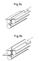
- FIGS. 2a and 2b A knife.
- Fig. 2a shows the start of folding a straight 2b the folded end of this sheet, when he has left the sheet entry zone, so that a subsequent sheet can enter.
- Fig. 3 is a combination folding machine consisting of a pocket folder 12 and an adjoining one Sword folding mechanism 14 shown.
- suction wheel 16 as part of a sheet feeder 20 transports sheets of paper from a tray to one Conveyor line that includes an alignment table.
- a Central control device 10 of a digital control system becomes a certain suction cycle Y1 for the suction wheel 16 established.
- Sheet detectors B1, B2, B4 to B7 are on different positions in the combination folding machine arranged and are covered during the sheet passage and deliver the signal level on and during the Pause the signal level off, as is shown in FIG. 6 is described in more detail.
- control device 10 of the digital control system the entire sensors and actuators of the folding machine are linked.
- the Control the signals of the sheet detectors B1, B2, B4, B5, B6, B7 and the incremental gear B3 and controls the Suction cycle Y1 of the suction wheel 16 and the sword cycle Y2, Y3.
- the bow detector B1 is in the immediate vicinity of the Suction wheel 16, the sheet detector B2 at the sheet inlet of the Pocket folder 12 and the sheet detector B4 at the pocket inlet a first folding pocket.
- the bow detector B5 is on Arch outlet of the pocket folding unit 12 arranged.
- the bow detector 1.84 leads from the time of the sheet entry to When the signal level disappears from the fold zone On. Only when the arc detector B4 turns the signal level off leads, the next sheet may go into the folding zone of the pocket folding unit 12 break in.
- Sheet detectors B6 and B7 are on a format adjustable Holder in a subsequent to the pocket folder 12 Sword folder 14 attached.
- the holder (see Fig. 5) is set so that the rear edge of the stop of the sword folding unit 14 transported the folding sheet Do not cover sheet detector B6 anymore.
- the location of the arc detectors B2, B4 and B5 is more accurate in Fig. 4 and the location the sheet detectors B6, B7 and the holder is more precise in Fig. 5 shown.
- After the sheet entry is with the falling Signal of the arc detector B6 acting as a signal generator Heavy stroke triggered.
- the arc detector B7 leads from the time of the sheet entry until the time of disappearance the signal level on from the folding zone. Only when the sensor B7 leads to the signal level Off, the next arc can be in the Run in the folding zone of the sword folding unit 14.
- the suction cycle control is adjusted to the correct pitch, so that the minimum Bow spacing on pocket and sword folding mechanism 12, 14 maintained becomes. There is a percentage security surcharge added to the measured minimum distance.
- the central control device 10 calculates by means of the Waveforms of the arc detectors B2, B4, B5, B6, B7 and the signals of the incremental encoder B3 the correct arc distance on the suction wheel 16.
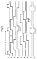
- the corresponding waveforms the arc detectors and incremental encoders are in Fig. 6 shown for a specific sheet format and a fold type.
- S6 is the suction cycle setting determined by the learning curve, which are normally maintained during production is designated Y1.
- S1 is the suction cycle period. With B1, B2 and B4 to B7 the signal levels are the corresponding arc detectors are shown. Designated S2 the arc distance on the suction wheel, S3 the arc distance in the Folding pocket of the pocket folding unit 12 and S4 the sheet spacing the switching states on the 14. Y2 and Y3 sword folding unit a sword clutch or a sword brake, which in Fig. 3 are not shown explicitly again.
- the operating performance of the folding machine shown in Fig. 3 is optimized in that the signals from the arc detectors B1, B2 and B4 to B7 and the incremental encoder B3 from the Control device 10 are processed as follows: the temporal distance between the fed to the sheet feeder 20 Trigger pulses will be at the lowest possible value regulated, at which a predetermined minimum distance between two pulse edges of the arc detectors B2 and B4 are not is undercut.
- the first pulse edge is the Trailing edge of a preceding sheet at sheet inlet 11 of the pocket folder 12 and the second pulse edge Leading edge of the following sheet.
- the sheet detector B7 at the sheet inlet of the sword folding unit 14 provides a pulse, the edge of which Is assigned to the trailing edge of a preceding sheet.
- the Bow detector B6 in turn provides a pulse with one Flank, which is the leading edge of a subsequent sheet assigned. From the corresponding difference we can the sheet spacing S4 (see FIG. 6) on the sword folding mechanism 14 determine.
- the pulse signal upon detection of the trailing edge of the preceding arc releases, as clearly shown in FIG. 5 is recognizable, the drive of the folding blade for a folding process from the sword coupling by means of the signal Y2 in the on state and the sword brake by means of the Signal Y3 is transferred to the off state. Because of this The process becomes the operating performance of the sword folding unit 14 and thus also optimized the entire combination folding machine, because it is impossible that the folding sword too is triggered at the wrong time and the following one Sheet enters the sword folding mechanism 14 too early.
- Another optimization of operational performance is the actual minimum distances during ongoing production to be measured and the arc distance by determining the trend S2 on suction wheel 16 to reduce or increase.
- the determined sheet lengths are used for sheet throughput control used.
- the bow detectors B2 and B4 are also used as a control of the complete sheet entry into the folding pocket.
- the signals emitted by the arc detectors B2 and B4 can in the control device 10 for two further functions are processed:
- a sheet that does not run to the pocket stop will not properly folded and leads to production problems.
- the path of the incoming and outgoing sheet saved and as a reference value for the Folded sheets used in production.
- the advantage of Pocket check is a folded sheet early is recognized and the folder drive is quickly switched off can be.
Landscapes
- Folding Of Thin Sheet-Like Materials, Special Discharging Devices, And Others (AREA)
Description
- Fig. 1a
- eine schematische Ansicht eines Taschenfalzwerkes mit einem sich darin befindlichen Bogen bei Falzbeginn,
- Fig. 1b
- das Taschenfalzwerk gemäß Fig. 1a mit dem fertiggefalzten Bogen,
- Fig. 2a
- ein Schwertfalzwerk mit einem sich darin befindlichen Bogen bei Falzbeginn,
- Fig. 2b
- das Schwertfalzwerk gemäß Fig. 2a mit dem fertiggefalzten Bogen,
- Fig. 3
- ein kombiniertes Taschen- und Schwertfalzwerk mit zahlreichen Bogendetektoren zur Durchführung des erfindungsgemäßen Verfahrens,
- Fig. 4
- einen Teil des im Kombinations-Falzwerk nach Fig. 3 enthaltenen Taschenfalzwerkes,
- Fig. 5
- in perspektivischer Ansicht ein im Kombinations-Falzwerk nach Fig. 3 einsetzbares Schwertfalzwerk,
- Fig. 6
- in Gegenüberstellung die Schaltzustände der im Kombinations-Falzwerk nach Fig. 3 vorgesehenen Bogendetektoren sowie die Schaltzustände von einigen weiteren darin enthaltenen Einrichtungen bei Durchführung des erfindungsgemäßen Verfahrens.
Claims (7)
- Verfahren zur Optimierung der Betriebsleistung einer Falzmaschine mit einem Bogenanleger (20) und mehreren aufeinanderfolgenden Falzstationen mittels einer zentralen Steuereinrichtung (10), in der Signale von Bogendetektoren (B1, B2, B4 bis B7) verarbeitet werden, die an verschiedenen Stellen der Falzmaschine entlang der Bogendurchlaufstrecke angeordnet sind, wobei der zeitliche Abstand zwischen den dem Bogenanleger (20) zugeführten Auslöseimpulsen auf den kleinstmöglichen Wert eingestellt, insbesondere geregelt wird, der einem Mindestabstand zwischen zwei Bogen entspricht, dadurch gekennzeichnet, daß ein vorgegebener Mindestabstand zwischen zwei Impulsflanken der Bogendetektoren (B2, B4; B6, B7), von denen die erste die Hinterkante eines vorausgehenden Bogens am Bogeneinlauf (11) einer Falzstation und die zweite die Vorderkante des darauffolgenden Bogens darstellt, nicht unterschritten wird, wobei die erste Impulsflanke von einem Bogendetektor (B4, B7) geliefert wird, der vom Zeitpunkt des Bogeneinlaufes bis zum Zeitpunkt des Verschwindens des Bogen aus der Falzzone einen gleichen Signalpegel liefert.
- Verfahren nach Anspruch 1, dadurch gekennzeichnet, daß die zweite Impulsflanke von einem Bogendetektor (B7) am Bogeneinlauf eines Schwertfalzwerkes (14) abgegeben wird, der in einem vorbestimmten Abstand hinter einem vorgelagerten, auf die Bogenlänge einstellbaren Bogendetektor (B6) angeordnet ist, dessen Impulssignal bei Erfassen der Hinter kante eines Bogens den Antrieb des Falzschwertes für einen Falzvorgang auslöst.
- Verfahren nach Anspruch 2, dadurch gekennzeichnet, daß der vorgelagerte Bogendetektor (B6) auf die Hinterkante eines am Anschlag des Schwertfalzwerkes (14) ausgerichteten Bogens eingestellt wird.
- Verfahren nach Anspruch 1, dadurch gekennzeichnet, daß die zwei Impulsflanken von einem Paar Bogendetektoren (B2, B4) an einem Taschenfalzwerk (12) abgegeben werden, wobei die zweite Impulsflanke der Vorderkante eines Bogens am Bogeneinlauf (11) und die erste Impulsflanke der Hinterkante eines aus einer Falztasche austretenden vorangehenden Bogens entspricht.
- Verfahren nach einem der vorstehenden Ansprüche, dadurch gekennzeichnet, daß für mehrere Falzstationen jeweils ein zugehöriger Mindestabstand zwischen zwei Impulsflanken der von den Bogendetektoren (B1, B2, B4 bis B7) am jeweiligen Bogeneinlauf (11) abgegebenen Impulssignale vorgegeben wird und der Abstand zwischen den Auslöseimpulsen für den Bogenanleger (20) so geregelt wird, daß keiner der vorgegebenen Mindestabstände unterschritten wird.
- Verfahren nach einem der vorstehenden Ansprüche, dadurch gekennzeichnet, daß Schwankungen im zeitlichen Auftreten der Impulsflanken durch Mittelung ausgeglichen werden.
- Verfahren nach einem der vorstehenden Ansprüche, dadurch gekennzeichnet, daß vor Produktionsbeginn ein einzelner Bogen als Lernbogen abgerufen wird und alle Falzstationen durchläuft, daß aus den von den Bogendetektoren (B1, B2, B4 bis B7) abgegebenen Signalen die Bogenlänge bestimmt wird und daß die Bogen-Durchlaufgeschwindigkeit der Falzmaschine auf den größtmöglichen Wert eingestellt wird, bei dem weder eine vorbestimmte Grenze der Bogen-Durchlaufgeschwindigkeit, noch ein vorbestimmter Grenzwert der sich aus Bogenlänge, Bogenabstand und Bogen-Durchlaufgeschwindigkeit ergebenden Taktfolge des Bogenanlegers (20) überschritten wird.
Applications Claiming Priority (4)
| Application Number | Priority Date | Filing Date | Title |
|---|---|---|---|
| DE19509323 | 1995-03-15 | ||
| DE19509323 | 1995-03-15 | ||
| DE19516437A DE19516437B4 (de) | 1995-03-15 | 1995-05-04 | Verfahren zur Optimierung der Betriebsleistung einer Falzmaschine |
| DE19516437 | 1995-05-04 |
Publications (3)
| Publication Number | Publication Date |
|---|---|
| EP0732293A2 EP0732293A2 (de) | 1996-09-18 |
| EP0732293A3 EP0732293A3 (de) | 1997-07-23 |
| EP0732293B1 true EP0732293B1 (de) | 2002-01-30 |
Family
ID=26013383
Family Applications (1)
| Application Number | Title | Priority Date | Filing Date |
|---|---|---|---|
| EP19960104141 Expired - Lifetime EP0732293B1 (de) | 1995-03-15 | 1996-03-15 | Verfahren zur Optimierung der Betriebsleistung einer Falzmaschine |
Country Status (2)
| Country | Link |
|---|---|
| EP (1) | EP0732293B1 (de) |
| PT (1) | PT732293E (de) |
Cited By (2)
| Publication number | Priority date | Publication date | Assignee | Title |
|---|---|---|---|---|
| DE102016203043A1 (de) | 2016-02-26 | 2017-08-31 | Heidelberger Druckmaschinen Ag | Verfahren zum Falzen von Bogen und Falzmaschine |
| WO2023194874A1 (en) * | 2022-04-05 | 2023-10-12 | Dandekar Sanjay Madhav | A system for operating a paper folding machine |
Families Citing this family (5)
| Publication number | Priority date | Publication date | Assignee | Title |
|---|---|---|---|---|
| DE19747997A1 (de) * | 1997-10-30 | 1999-05-12 | Stahl Gmbh & Co Maschf | Taschenfalzwerk und Verfahren zur Registerregelung eines Taschenfalzwerks |
| US6440049B1 (en) * | 1998-02-02 | 2002-08-27 | Heidelberger Druckmaschinen Ag | Folder with early warning jam detection system and related method |
| DE19860070A1 (de) * | 1998-12-23 | 2000-06-29 | Stahl Gmbh & Co Maschf | Taschenfalzwerk und Verfahren zur Registerregelung eines Taschenfalzwerks |
| DE10059271A1 (de) * | 2000-11-29 | 2002-06-06 | Heidelberger Druckmasch Ag | Falzschwertsteuerung |
| DE102006021901B4 (de) * | 2006-05-11 | 2008-08-21 | Koenig & Bauer Aktiengesellschaft | Verfahren zum Längsfalzen von zu falzenden Produkten |
Family Cites Families (3)
| Publication number | Priority date | Publication date | Assignee | Title |
|---|---|---|---|---|
| DE3935056C2 (de) * | 1989-10-20 | 1996-07-11 | Stahl Gmbh & Co Maschf | Verfahren zur Kontrolle des Bogendurchlaufs in einer Falzmaschine und Vorrichtung zur Durchführung des Verfahrens |
| DE4013401A1 (de) * | 1990-04-26 | 1991-10-31 | Binder & Co Masch Oppenweiler | Verfahren zum einrichten und steuern einer falzmaschine |
| DE4315095A1 (de) * | 1993-05-06 | 1994-11-10 | Stahl Gmbh & Co Maschf | Verfahren zum Betreiben einer Falzmaschine |
-
1996
- 1996-03-15 EP EP19960104141 patent/EP0732293B1/de not_active Expired - Lifetime
- 1996-03-15 PT PT96104141T patent/PT732293E/pt unknown
Cited By (3)
| Publication number | Priority date | Publication date | Assignee | Title |
|---|---|---|---|---|
| DE102016203043A1 (de) | 2016-02-26 | 2017-08-31 | Heidelberger Druckmaschinen Ag | Verfahren zum Falzen von Bogen und Falzmaschine |
| DE102016203043B4 (de) | 2016-02-26 | 2018-05-09 | Heidelberger Druckmaschinen Ag | Verfahren zum Falzen von Bogen und Falzmaschine |
| WO2023194874A1 (en) * | 2022-04-05 | 2023-10-12 | Dandekar Sanjay Madhav | A system for operating a paper folding machine |
Also Published As
| Publication number | Publication date |
|---|---|
| PT732293E (pt) | 2002-07-31 |
| EP0732293A3 (de) | 1997-07-23 |
| EP0732293A2 (de) | 1996-09-18 |
Similar Documents
| Publication | Publication Date | Title |
|---|---|---|
| DE3319247C2 (de) | Verfahren und Vorrichtung zum Fördern von Blattlagen zu einer Weiterverarbeitungsmaschine | |
| DE4241502C2 (de) | Vorrichtung zum fortwährenden Zuführen einzelner Blätter zu einem Blattverarbeitungsabschnitt einer Blattverarbeitungseinrichtung | |
| DE2118587C3 (de) | Einrichtung zum gegenseitigen Anpassen der Fördergeschwindigkeiten zweier Förderer | |
| DE2457112C3 (de) | Blatttransportvorrichtung | |
| CH617906A5 (de) | ||
| EP0873273B1 (de) | Falzapparat mit signaturweiche | |
| DE3301722C2 (de) | Verfahren und Vorrichtung zur paßgerechten Zuführung von Bogen an bogenverarbeitenden Maschinen | |
| EP1811851B1 (de) | Verfahren und vorrichtung zum schneiden von würsten | |
| EP2363363A2 (de) | Verfahren und Vorrichtung zur Richtungsumkehr beim Transport von Gegenständen | |
| EP0732293B1 (de) | Verfahren zur Optimierung der Betriebsleistung einer Falzmaschine | |
| EP1281653A2 (de) | Vorrichtung zum rotativen Bearbeiten von blattförmigen Bedruckstoffen | |
| EP0453909B1 (de) | Verfahren zum Einrichten und Steuern einer Falzmaschine | |
| EP1013589B1 (de) | Taschenfalzwerk und Verfahren zur Registerregelung eines Taschenfalzwerks | |
| EP1421022A1 (de) | Verfahren und anordnung zum erkennen von doppelabzügen | |
| DE2202851B2 (de) | Kontrollvorrichtung zur automatischen druckanstellung und spaeteren einlauf- und anlegekontrolle bei bogenfuehrenden druckmaschinen | |
| DE3935056C2 (de) | Verfahren zur Kontrolle des Bogendurchlaufs in einer Falzmaschine und Vorrichtung zur Durchführung des Verfahrens | |
| EP2695741B1 (de) | Fadenheftmaschine | |
| CH672776A5 (de) | ||
| DE19516437B4 (de) | Verfahren zur Optimierung der Betriebsleistung einer Falzmaschine | |
| EP1588965B1 (de) | Verfahren zur Lagekontrolle eines in einer Falzmaschine transportierten Bogens | |
| DE19506463C2 (de) | Stauüberwachungseinrichtung für eine Transportvorrichtung für Papier, insbesondere für eine Papierbahn | |
| EP2492107B1 (de) | Fadenheftmaschine | |
| DE2051065A1 (de) | Überwachungseinrichtung auf Registerhaltigkeit von bedruckten Bögen | |
| EP1854753B1 (de) | Falzapparat und ein Verfahren zum Längsfalzen von Produkten von unterschiedlicher Breite | |
| DE2747598C2 (de) | Einrichtung zur Regelung der Arbeitsgeschwindigkeit mehrerer hintereinandergeschalteter Flaschenbehandlungsmaschinen |
Legal Events
| Date | Code | Title | Description |
|---|---|---|---|
| PUAI | Public reference made under article 153(3) epc to a published international application that has entered the european phase |
Free format text: ORIGINAL CODE: 0009012 |
|
| AK | Designated contracting states |
Kind code of ref document: A2 Designated state(s): CH DE IT LI PT |
|
| PUAL | Search report despatched |
Free format text: ORIGINAL CODE: 0009013 |
|
| AK | Designated contracting states |
Kind code of ref document: A3 Designated state(s): CH DE IT LI PT |
|
| 17P | Request for examination filed |
Effective date: 19970922 |
|
| 17Q | First examination report despatched |
Effective date: 19990628 |
|
| RAP1 | Party data changed (applicant data changed or rights of an application transferred) |
Owner name: HEIDELBERGER DRUCKMASCHINEN AKTIENGESELLSCHAFT |
|
| GRAG | Despatch of communication of intention to grant |
Free format text: ORIGINAL CODE: EPIDOS AGRA |
|
| GRAG | Despatch of communication of intention to grant |
Free format text: ORIGINAL CODE: EPIDOS AGRA |
|
| GRAG | Despatch of communication of intention to grant |
Free format text: ORIGINAL CODE: EPIDOS AGRA |
|
| GRAH | Despatch of communication of intention to grant a patent |
Free format text: ORIGINAL CODE: EPIDOS IGRA |
|
| GRAH | Despatch of communication of intention to grant a patent |
Free format text: ORIGINAL CODE: EPIDOS IGRA |
|
| GRAA | (expected) grant |
Free format text: ORIGINAL CODE: 0009210 |
|
| AK | Designated contracting states |
Kind code of ref document: B1 Designated state(s): CH DE IT LI PT |
|
| PG25 | Lapsed in a contracting state [announced via postgrant information from national office to epo] |
Ref country code: IT Free format text: LAPSE BECAUSE OF FAILURE TO SUBMIT A TRANSLATION OF THE DESCRIPTION OR TO PAY THE FEE WITHIN THE PRE;WARNING: LAPSES OF ITALIAN PATENTS WITH EFFECTIVE DATE BEFORE 2007 MAY HAVE OCCURRED AT ANY TIME BEFORE 2007. THE CORRECT EFFECTIVE DATE MAY BE DIFFERENT FROM THE ONE RECORDED.SCRIBED TIME-LIMIT Effective date: 20020130 |
|
| REG | Reference to a national code |
Ref country code: CH Ref legal event code: EP |
|
| REF | Corresponds to: |
Ref document number: 59608655 Country of ref document: DE Date of ref document: 20020314 |
|
| REG | Reference to a national code |
Ref country code: PT Ref legal event code: SC4A Free format text: AVAILABILITY OF NATIONAL TRANSLATION Effective date: 20020412 |
|
| PLBQ | Unpublished change to opponent data |
Free format text: ORIGINAL CODE: EPIDOS OPPO |
|
| PLBI | Opposition filed |
Free format text: ORIGINAL CODE: 0009260 |
|
| PLBF | Reply of patent proprietor to notice(s) of opposition |
Free format text: ORIGINAL CODE: EPIDOS OBSO |
|
| PLBQ | Unpublished change to opponent data |
Free format text: ORIGINAL CODE: EPIDOS OPPO |
|
| PLAB | Opposition data, opponent's data or that of the opponent's representative modified |
Free format text: ORIGINAL CODE: 0009299OPPO |
|
| PLBI | Opposition filed |
Free format text: ORIGINAL CODE: 0009260 |
|
| 26 | Opposition filed |
Opponent name: MASCHINENBAU OPPENWEILER BINDER GMBH & CO Effective date: 20021030 |
|
| 26 | Opposition filed |
Opponent name: MASCHINENBAU OPPENWEILER BINDER GMBH & CO Effective date: 20021030 |
|
| PLBF | Reply of patent proprietor to notice(s) of opposition |
Free format text: ORIGINAL CODE: EPIDOS OBSO |
|
| PLBF | Reply of patent proprietor to notice(s) of opposition |
Free format text: ORIGINAL CODE: EPIDOS OBSO |
|
| PLCK | Communication despatched that opposition was rejected |
Free format text: ORIGINAL CODE: EPIDOSNREJ1 |
|
| APBP | Date of receipt of notice of appeal recorded |
Free format text: ORIGINAL CODE: EPIDOSNNOA2O |
|
| APBQ | Date of receipt of statement of grounds of appeal recorded |
Free format text: ORIGINAL CODE: EPIDOSNNOA3O |
|
| APAA | Appeal reference recorded |
Free format text: ORIGINAL CODE: EPIDOS REFN |
|
| APBU | Appeal procedure closed |
Free format text: ORIGINAL CODE: EPIDOSNNOA9O |
|
| APAH | Appeal reference modified |
Free format text: ORIGINAL CODE: EPIDOSCREFNO |
|
| PLBN | Opposition rejected |
Free format text: ORIGINAL CODE: 0009273 |
|
| STAA | Information on the status of an ep patent application or granted ep patent |
Free format text: STATUS: OPPOSITION REJECTED |
|
| 27O | Opposition rejected |
Effective date: 20050601 |
|
| PGFP | Annual fee paid to national office [announced via postgrant information from national office to epo] |
Ref country code: CH Payment date: 20120425 Year of fee payment: 17 |
|
| PGFP | Annual fee paid to national office [announced via postgrant information from national office to epo] |
Ref country code: PT Payment date: 20130228 Year of fee payment: 18 |
|
| REG | Reference to a national code |
Ref country code: CH Ref legal event code: PL |
|
| PG25 | Lapsed in a contracting state [announced via postgrant information from national office to epo] |
Ref country code: CH Free format text: LAPSE BECAUSE OF NON-PAYMENT OF DUE FEES Effective date: 20130331 Ref country code: LI Free format text: LAPSE BECAUSE OF NON-PAYMENT OF DUE FEES Effective date: 20130331 |
|
| PGFP | Annual fee paid to national office [announced via postgrant information from national office to epo] |
Ref country code: DE Payment date: 20140331 Year of fee payment: 19 |
|
| REG | Reference to a national code |
Ref country code: PT Ref legal event code: MM4A Free format text: LAPSE DUE TO NON-PAYMENT OF FEES Effective date: 20140915 |
|
| PG25 | Lapsed in a contracting state [announced via postgrant information from national office to epo] |
Ref country code: PT Free format text: LAPSE BECAUSE OF NON-PAYMENT OF DUE FEES Effective date: 20140915 |
|
| REG | Reference to a national code |
Ref country code: DE Ref legal event code: R119 Ref document number: 59608655 Country of ref document: DE |
|
| PG25 | Lapsed in a contracting state [announced via postgrant information from national office to epo] |
Ref country code: DE Free format text: LAPSE BECAUSE OF NON-PAYMENT OF DUE FEES Effective date: 20151001 |