EP0731258B1 - Abgaskrümmer - Google Patents
Abgaskrümmer Download PDFInfo
- Publication number
- EP0731258B1 EP0731258B1 EP96102547A EP96102547A EP0731258B1 EP 0731258 B1 EP0731258 B1 EP 0731258B1 EP 96102547 A EP96102547 A EP 96102547A EP 96102547 A EP96102547 A EP 96102547A EP 0731258 B1 EP0731258 B1 EP 0731258B1
- Authority
- EP
- European Patent Office
- Prior art keywords
- flange
- pipes
- manifold
- exhaust manifold
- cylinder
- Prior art date
- Legal status (The legal status is an assumption and is not a legal conclusion. Google has not performed a legal analysis and makes no representation as to the accuracy of the status listed.)
- Expired - Lifetime
Links
Images

Classifications
-
- F—MECHANICAL ENGINEERING; LIGHTING; HEATING; WEAPONS; BLASTING
- F01—MACHINES OR ENGINES IN GENERAL; ENGINE PLANTS IN GENERAL; STEAM ENGINES
- F01N—GAS-FLOW SILENCERS OR EXHAUST APPARATUS FOR MACHINES OR ENGINES IN GENERAL; GAS-FLOW SILENCERS OR EXHAUST APPARATUS FOR INTERNAL-COMBUSTION ENGINES
- F01N13/00—Exhaust or silencing apparatus characterised by constructional features
- F01N13/08—Other arrangements or adaptations of exhaust conduits
- F01N13/10—Other arrangements or adaptations of exhaust conduits of exhaust manifolds
- F01N13/102—Other arrangements or adaptations of exhaust conduits of exhaust manifolds having thermal insulation
Definitions
- the invention is based on an air-gap-insulated exhaust manifold for Internal combustion engines according to the preamble of claim 1.
- the invention has for its object one in fluidic and manufacturing technology improved exhaust manifold create.
- the invention proposes a manifold with features mentioned in claim 1. Developments of the invention are the subject of subclaims.
- the invention therefore proposes that in a case with three cylinder tubes it is provided that the first two cylinder tubes are brought together in parallel are and with an axially aligned intermediate header get connected.
- This intermediate header pipe can then be used the third cylinder tube in turn aligned and merged then a connection, for example by plugging in, with the header pipe running in the same direction.
- the intermediate manifold when the intermediate manifold is brought together with the third cylinder tube the intermediate manifold a double as large a cross section as the cylinder tube since it is the gas flow from two cylinder tubes.
- the first two cylinder tubes are like this shaped so that in its end region the direction of the intermediate header exhibit. This curvature, for example by 90 °, can be so take place that a gradual deflection of the gas jet is effected. In its end area, that is, when the gas flows into the intermediate manifold, the gases are already in the same direction as the intermediate manifold, so that there are no one-sided local impacts on wall parts.
- the making of holes in the wall of the intermediate header omitted, since the first two cylinder tubes axially in there anyway Opened intermediate header pipe inserted or connected to it become.
- the one another adjacent merged ends of the cylinder tubes along one especially abut a flat surface.
- the invention proposes that the cross section through the merged Ends of the first two cylinder tubes each with a semicircle, can correspond to a semi-oval or another semi-shape. If for example, the intermediate header pipe has a circular cross section has, contain the first two cylinder tubes in their end region a semicircular cross section. With an oval intermediate header pipe the cross section would accordingly have the shape of a have half oval.
- the intermediate header pipes secured against slipping by lugs, bulges or projections be, these are arranged so that temperature expansions are still possible.
- End of cylinder tubes is especially in the case of air gap insulated Exhaust manifolds applicable in which the gas-bearing inner pipe system is arranged within an outer shell, which with the cylinder flange and connected to the collecting flange, in particular welded is.
- the connection between the cylinder tubes, the manifold and the intermediate manifolds by simple Plug in because gas tightness is no longer required.
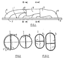
- the exhaust manifold shown in Fig. 1 includes a flange 1 which in its left part in Fig. 1, which is about two thirds of the total length extends as a cylinder flange 2 is formed. In his mind of it right adjoining Part of the flange 1 is then designed as a collecting flange 3.
- Starting from the cylinder flange 2 are three cylinder tubes 4 attached to the flange, for example by welding. Each cylinder tube 4 has an opening in the cylinder flange 2 in connection so that the through the opening of the Flange 2 passing gas jet through the corresponding Cylinder tube 4 is derived.
- the cylinder tubes 4 are approximately on the cylinder flange 2 attached at right angles and extend from there on over a quarter arch in one direction that essentially parallel or slightly oblique to the surface of the flange 1 runs.
- the first cylinder tube on the far left in FIG. 1, extends to beyond the second cylinder tube 4, the two first cylinder tubes 4 abut each other and in their End regions 5 run parallel to each other. Both end areas 5 of the first two cylinder tubes 4 are in an intermediate header tube 6 inserted, the axis of which is the same direction has as the end regions 5 of the cylinder tubes 4. It occurs So in the intermediate header 6 no deflection of the two the two cylinder tubes 4 emerging gas jets.
- the intermediate header 6 then continues approximately straight up to the also coaxially aligned manifold 7th
- the third cylinder tube 4 which also has a quarter arc is curved, is parallel in its end region to the end region of the intermediate header 6 and lies with his wall on this. It is next to the intermediate header 6 inserted horizontally into the end of the collecting tube 7, so that both the gas jet emerging from the intermediate header 6 as well as the gas jet from the cylinder tube 4 when entering run parallel to each other in the collecting tube 7.
- the Collecting tube 7 now picks up and directs all gas jets over the sheet 8 at its end to the as Collective flange acting part 3 of the flange.
- an outer shell for example in the form of a hood, arranged around with the flange 1 is welded gas-tight.
- Fig. 2 shows in its right half a section through the Arrangement of Fig. 1 along the line B-B, i.e. H. at the Point at which the end regions 5 of the two cylinder tubes 4 into the intermediate collecting tube with a circular cross-section open out.
- the cross section of the two end regions 5 corresponds to a semicircle, with a flat one Partition between the two walls that are close together issue.
- the intermediate header 6 is a close fit created around the two end regions 5.
- Both end areas 5 of the first two cylinder tubes 4 have the same Cross-sectional shape and the same cross-sectional size. From there the same amount of gas flows out of both cylinder tubes this way an equal speed of the two Gas flows reached when entering the intermediate header 6.
- Fig. 2 shows on the left a cross section through the arrangement along the line A-A.
- the end region 5 opens at this point of the third cylinder tube 4 together with the end region of the Intermediate header tube 6 in the header tube 7.
- the End region of the intermediate header tube 6 along a plane Partition surface at the end region of the third cylinder tube 4.
- the cross section of the intermediate header tube 6 is approximately twice as large as the cross section of the cylinder tube 4 since from the intermediate header 6 the gas flow from the two first cylinder tubes 4 emerges.
- FIG. 3 shows corresponding representations in an exhaust system, in which both the header pipe and the intermediate header pipe 6 has an oval cross section.
- Fig. 4 shows a longitudinal section through part of a Arrangement on an enlarged scale.
- the cylinder flange 2 has a plurality of openings 10 already mentioned, from which the exhaust gases from the internal combustion engine escape.
- every opening 10 is the end of a cylinder tube 4 assigned to the engine used and welded.
- the opposite ends 5 of the first two cylinder tubes 4 are in the intermediate header 6 inserted.
- the two ends 5 of the first two Cylinder tubes 4 are neither with each other nor with the intermediate header 6 welded or soldered, so that due to the Eliminating such a connection further reduced costs can be.
- the first cylinder tube 4 contains just before its end portion 5 has an outward projection Shape of a bead 11, for example, over a Extends part of its circumference.
- the intermediate header 6 together with the third cylinder tube 4 in the manifold 7 inserted.
- the intermediate header pipe 6 contains the intermediate header pipe 6 a bead 12 corresponding to the bead 11 Distance of the bead 12 from the associated end edge of the Intermediate manifold 6 is chosen so that thermal stresses can be included.
- the two beads 11, 12 are intended to prevent the intermediate collecting tube from slipping off 7 for temperature changes and for Prevent vibrations.
- Fig. 6 shows again the arrangement of Fig. 1, this time an outer shell 13 is broken off at the ends of the flange 1 is shown, along the edge of the flange 1 with this is welded.
- the flange 13 can also have holes 14, which have corresponding connection holes 15 of flange 1 match.
Landscapes
- Engineering & Computer Science (AREA)
- Chemical & Material Sciences (AREA)
- Combustion & Propulsion (AREA)
- Mechanical Engineering (AREA)
- General Engineering & Computer Science (AREA)
- Exhaust Silencers (AREA)
- Control Of Throttle Valves Provided In The Intake System Or In The Exhaust System (AREA)
- Quick-Acting Or Multi-Walled Pipe Joints (AREA)
Description
- Fig. 1
- eine schematische Seitenansicht eines Abgaskrümmers, bei dem der Zylinderflansch einstückig in einen Sammelflansch übergeht;
- Fig. 2
- Querschnitte durch die Anordnung der Fig. 1 an zwei Stellen;
- Fig. 3
- Querschnitte durch eine ähnliche Anordnung bei einer anderen Außenform;
- Fig. 4
- einen Teillängsschnitt durch einen Abgaskrümmer mit drei Zylinderrohren;
- Fig. 5
- einen Längsschnitt durch den Abgaskrümmer der Fig. 1.
Claims (7)
- Luftspaltisolierter Abgaskrümmer, mit einem Zylinderflansch (2) zur Anbringung des Krümmers an einem Zylinderkopf, einem Sammelflansch (3) zum Anschließen eines weiterführenden Rohrs, einer Außenschale (13), die mit dem Zylinderflansch (2) und dem Sammelflansch (3) verbunden ist, sowie mit einem gasführenden Innenrohrsystem innerhalb der Außenschale (13), das ein mit dem Sammelflansch (3) verbundenes Sammelrohr (7) und mindestens drei mit dem Zylinderflansch (2) verbundene Zylinderrohre (4) aufweist,
dadurch gekennzeichnet, daß die Enden (5) der ersten beiden Zylinderrohre (4) parallel zueinander verlaufen,
aneinander anliegend angeordnet und mit einem axial ausgerichteten Zwischensammelrohr (6) verbunden, insbesondere in dieses eingesteckt sind, das seinerseits mit dem dritten Zylinderrohr (4) im Endbereich parallel zueinander verlaufend und aneinander anliegend angeordnet sowie mit diesem im Endbereich zusammengefaßt und mit dem Sammelrohr (7) oder einem weiteren Zwischensammelrohr verbunden, insbesondere in dieses eingesteckt ist. - Abgaskrümmer nach Anspruch 1, bei dem die aneinander anliegenden zusammengeführten Enden (5) der Zylinderrohre (4) längs einer insbesondere ebenen Fläche aneinander anliegen.
- Abgaskrümmer nach Anspruch 1 oder 2, bei dem der Querschnitt durch die zusammengeführten Enden (5) der beiden ersten Zylinderrohre (4) jeweils einem Halbkreis oder einem Halboval entspricht.
- Abgaskrümmer nach einem der vorhergehenden Ansprüche, bei dem die Zwischensammelrohre (6) zwischen Vorsprüngen (11, 12) oder Ausbeulungen gehaltert sind.
- Abgaskrümmer nach einem der vorhergehenden Ansprüche, bei dem das Sammelrohr (7) und/oder die Zwischensammelrohre (6) einen dem gemeinsamen Querschnitt der zusammengeführten Zylinderrohre (4) entsprechenden Querschnitt aufweisen.
- Abgaskrümmer nach einem der vorhergehenden Ansprüche, bei dem die Querschnittsaufteilung der Zwischensammelrohre (6) und/oder des Sammelrohrs (7) der Zahl der zusammengeführten Zylinderrohre (4) entspricht.
- Abgaskrümmer nach einem der vorhergehenden Ansprüche, bei dem die Zylinderrohre (4), das Sammelrohr (7) und die Zwischensammelrohre (6) durch Stecken miteinander verbunden sind.
Applications Claiming Priority (2)
| Application Number | Priority Date | Filing Date | Title |
|---|---|---|---|
| DE19507439 | 1995-03-03 | ||
| DE19507439A DE19507439A1 (de) | 1995-03-03 | 1995-03-03 | Auspuffkrümmer |
Publications (2)
| Publication Number | Publication Date |
|---|---|
| EP0731258A1 EP0731258A1 (de) | 1996-09-11 |
| EP0731258B1 true EP0731258B1 (de) | 2002-09-04 |
Family
ID=7755538
Family Applications (1)
| Application Number | Title | Priority Date | Filing Date |
|---|---|---|---|
| EP96102547A Expired - Lifetime EP0731258B1 (de) | 1995-03-03 | 1996-02-21 | Abgaskrümmer |
Country Status (4)
| Country | Link |
|---|---|
| EP (1) | EP0731258B1 (de) |
| AT (1) | ATE223556T1 (de) |
| DE (2) | DE19507439A1 (de) |
| ES (1) | ES2178683T3 (de) |
Cited By (2)
| Publication number | Priority date | Publication date | Assignee | Title |
|---|---|---|---|---|
| DE19917604C5 (de) * | 1998-04-20 | 2009-09-10 | Honda Giken Kogyo K.K. | Wärmeisolierter Abgaskrümmer |
| WO2025083079A1 (de) * | 2023-10-17 | 2025-04-24 | Rolls-Royce Solutions GmbH | Strömungsvorrichtung, brennkraftmaschine und verfahren zum zusammenführen zweier fluidströme mit einer solchen strömungsvorrichtung |
Families Citing this family (7)
| Publication number | Priority date | Publication date | Assignee | Title |
|---|---|---|---|---|
| DE19957979B4 (de) * | 1999-12-02 | 2006-08-10 | Audi Ag | Abgaskrümmer |
| DE10219269A1 (de) * | 2002-04-30 | 2003-11-20 | Zeuna Staerker Kg | Zweischalige, luftspaltisolierte Abgaszusammenführung und Verfahren zu deren Herstellung |
| DE10261879B4 (de) * | 2002-12-20 | 2012-09-27 | Volkswagen Ag | Abgassammelrohr |
| DE602004006698T2 (de) * | 2003-12-01 | 2007-10-04 | Nissan Motor Co., Ltd., Yokohama | Abgaskrümmer für eine Brennkraftmaschine |
| DE102009001542A1 (de) | 2009-03-13 | 2010-10-07 | Ford Global Technologies, LLC, Dearborn | Zylinderkopf für einen Saugmotor und Verwendung eines derartigen Zylinderkopfes |
| USD812100S1 (en) | 2015-03-31 | 2018-03-06 | Litchfield Imports Limited | Exhaust manifold |
| CN114135380B (zh) * | 2022-01-27 | 2023-01-06 | 潍柴动力股份有限公司 | 一种排气歧管 |
Family Cites Families (8)
| Publication number | Priority date | Publication date | Assignee | Title |
|---|---|---|---|---|
| US2344863A (en) * | 1942-04-09 | 1944-03-21 | Continental Motors Corp | Internal combustion engine |
| US3043094A (en) * | 1960-02-29 | 1962-07-10 | Alco Products Inc | Exhaust manifolds |
| JPH01138311A (ja) * | 1987-11-24 | 1989-05-31 | Mazda Motor Corp | エンジンの排気通路構造 |
| DE69129068T2 (de) * | 1990-08-13 | 1998-07-30 | Flowmaster Inc | Sammelrohranlage für brennkraftmaschine und verfahren |
| JP2632601B2 (ja) * | 1991-02-18 | 1997-07-23 | 株式会社ユタカ技研 | 排気管 |
| DE4226171A1 (de) * | 1992-08-07 | 1994-02-10 | Bischoff Erhardt Gmbh Co Kg | Abgaskrümmer |
| US5299419A (en) * | 1992-11-02 | 1994-04-05 | Bittle James J | Gas flow headers for internal combustion engines |
| DE4342572C1 (de) * | 1993-12-14 | 1994-11-24 | Mtu Friedrichshafen Gmbh | Abgasanlage für eine aufgeladene Brennkraftmaschine |
-
1995
- 1995-03-03 DE DE19507439A patent/DE19507439A1/de not_active Withdrawn
-
1996
- 1996-02-21 EP EP96102547A patent/EP0731258B1/de not_active Expired - Lifetime
- 1996-02-21 AT AT96102547T patent/ATE223556T1/de not_active IP Right Cessation
- 1996-02-21 ES ES96102547T patent/ES2178683T3/es not_active Expired - Lifetime
- 1996-02-21 DE DE59609613T patent/DE59609613D1/de not_active Expired - Lifetime
Cited By (2)
| Publication number | Priority date | Publication date | Assignee | Title |
|---|---|---|---|---|
| DE19917604C5 (de) * | 1998-04-20 | 2009-09-10 | Honda Giken Kogyo K.K. | Wärmeisolierter Abgaskrümmer |
| WO2025083079A1 (de) * | 2023-10-17 | 2025-04-24 | Rolls-Royce Solutions GmbH | Strömungsvorrichtung, brennkraftmaschine und verfahren zum zusammenführen zweier fluidströme mit einer solchen strömungsvorrichtung |
Also Published As
| Publication number | Publication date |
|---|---|
| DE19507439A1 (de) | 1996-09-05 |
| EP0731258A1 (de) | 1996-09-11 |
| ATE223556T1 (de) | 2002-09-15 |
| DE59609613D1 (de) | 2002-10-10 |
| ES2178683T3 (es) | 2003-01-01 |
Similar Documents
| Publication | Publication Date | Title |
|---|---|---|
| EP0735251B1 (de) | Abgaskrümmer für eine Brennkraftmaschine | |
| EP0737803B1 (de) | Abgassammelrohr, insbesondere für eine Brennkraftmaschine in einem Kraftfahrzeug, und Verfahren zu dessen Herstellung | |
| EP0582985A1 (de) | Abgaskrümmer | |
| DE2033434A1 (de) | Abgassammler | |
| DE69915994T2 (de) | Querstromschalldämpfer mit Leitblechen | |
| EP0731258B1 (de) | Abgaskrümmer | |
| EP0955453A2 (de) | Abgaskrümmer | |
| EP0023041A1 (de) | Aussengehäuse für einen Abgasschalldämpfer für Brennkraftmaschinen | |
| EP2921670B1 (de) | Abgaskrümmer für eine Abgasanlage eines Verbrennungsmotors | |
| DE19523532A1 (de) | Katalysatoranordnung mit zwei- oder mehrsträngiger Abgasführung | |
| DE19508217A1 (de) | Metallischer Wabenkörper | |
| DE10045499A1 (de) | Auspuffsystem für ein Motorrad | |
| DE102004018693B4 (de) | Abgasanlage | |
| DE10144015A1 (de) | Abgasanlage für mehrzylindrige Verbrennungsmotoren | |
| EP1367234B1 (de) | Doppelwandige Abgasleitung mit Flansch | |
| DE102008018668B4 (de) | Abgaskrümmer und Abgasrohr für Verbrennungsmotoren | |
| DE19526084A1 (de) | Abgasrohrkrümmer | |
| DE112004000717B4 (de) | Organ einer Auspuffleitung eines Kraftfahrzeugs | |
| EP1199450A2 (de) | Abgaskrümmer | |
| DE19952648A1 (de) | Luftspaltisolierter Schalenkrümmer | |
| DE4316870A1 (de) | Vorrichtung zum Reinigen von Verbrennungsmotor-Abgasen sowie Verfahren zu deren Herstellung | |
| EP0745805A2 (de) | Heizkessel | |
| DE3332052C2 (de) | Schalldämpfer | |
| DE19832627A1 (de) | Vorrichtung zum Einblasen von Sekundärluft in den Abgasbereich einer Brennkraftmaschine | |
| DE10359073A1 (de) | Abgaskrümmer |
Legal Events
| Date | Code | Title | Description |
|---|---|---|---|
| PUAI | Public reference made under article 153(3) epc to a published international application that has entered the european phase |
Free format text: ORIGINAL CODE: 0009012 |
|
| AK | Designated contracting states |
Kind code of ref document: A1 Designated state(s): AT BE DE ES FR GB IT SE |
|
| 17P | Request for examination filed |
Effective date: 19970226 |
|
| 17Q | First examination report despatched |
Effective date: 19980921 |
|
| RAP1 | Party data changed (applicant data changed or rights of an application transferred) |
Owner name: FRIEDRICH BOYSEN GMBH & CO. KG |
|
| GRAG | Despatch of communication of intention to grant |
Free format text: ORIGINAL CODE: EPIDOS AGRA |
|
| GRAG | Despatch of communication of intention to grant |
Free format text: ORIGINAL CODE: EPIDOS AGRA |
|
| GRAH | Despatch of communication of intention to grant a patent |
Free format text: ORIGINAL CODE: EPIDOS IGRA |
|
| GRAH | Despatch of communication of intention to grant a patent |
Free format text: ORIGINAL CODE: EPIDOS IGRA |
|
| GRAA | (expected) grant |
Free format text: ORIGINAL CODE: 0009210 |
|
| AK | Designated contracting states |
Kind code of ref document: B1 Designated state(s): AT BE DE ES FR GB IT SE |
|
| REF | Corresponds to: |
Ref document number: 223556 Country of ref document: AT Date of ref document: 20020915 Kind code of ref document: T |
|
| REG | Reference to a national code |
Ref country code: GB Ref legal event code: FG4D Free format text: NOT ENGLISH |
|
| REF | Corresponds to: |
Ref document number: 59609613 Country of ref document: DE Date of ref document: 20021010 |
|
| GBT | Gb: translation of ep patent filed (gb section 77(6)(a)/1977) |
Effective date: 20021014 |
|
| ET | Fr: translation filed | ||
| REG | Reference to a national code |
Ref country code: ES Ref legal event code: FG2A Ref document number: 2178683 Country of ref document: ES Kind code of ref document: T3 |
|
| PLBE | No opposition filed within time limit |
Free format text: ORIGINAL CODE: 0009261 |
|
| STAA | Information on the status of an ep patent application or granted ep patent |
Free format text: STATUS: NO OPPOSITION FILED WITHIN TIME LIMIT |
|
| 26N | No opposition filed |
Effective date: 20030605 |
|
| PGFP | Annual fee paid to national office [announced via postgrant information from national office to epo] |
Ref country code: ES Payment date: 20090219 Year of fee payment: 14 Ref country code: AT Payment date: 20090218 Year of fee payment: 14 |
|
| PGFP | Annual fee paid to national office [announced via postgrant information from national office to epo] |
Ref country code: SE Payment date: 20090216 Year of fee payment: 14 Ref country code: IT Payment date: 20090221 Year of fee payment: 14 |
|
| PGFP | Annual fee paid to national office [announced via postgrant information from national office to epo] |
Ref country code: BE Payment date: 20090408 Year of fee payment: 14 |
|
| PGFP | Annual fee paid to national office [announced via postgrant information from national office to epo] |
Ref country code: FR Payment date: 20090213 Year of fee payment: 14 |
|
| PGFP | Annual fee paid to national office [announced via postgrant information from national office to epo] |
Ref country code: GB Payment date: 20100218 Year of fee payment: 15 |
|
| BERE | Be: lapsed |
Owner name: FRIEDRICH *BOYSEN G.M.B.H. & CO. K.G. Effective date: 20100228 |
|
| EUG | Se: european patent has lapsed | ||
| REG | Reference to a national code |
Ref country code: FR Ref legal event code: ST Effective date: 20101029 |
|
| PG25 | Lapsed in a contracting state [announced via postgrant information from national office to epo] |
Ref country code: AT Free format text: LAPSE BECAUSE OF NON-PAYMENT OF DUE FEES Effective date: 20100221 |
|
| PG25 | Lapsed in a contracting state [announced via postgrant information from national office to epo] |
Ref country code: FR Free format text: LAPSE BECAUSE OF NON-PAYMENT OF DUE FEES Effective date: 20100301 |
|
| PG25 | Lapsed in a contracting state [announced via postgrant information from national office to epo] |
Ref country code: BE Free format text: LAPSE BECAUSE OF NON-PAYMENT OF DUE FEES Effective date: 20100228 |
|
| REG | Reference to a national code |
Ref country code: ES Ref legal event code: FD2A Effective date: 20110324 |
|
| PG25 | Lapsed in a contracting state [announced via postgrant information from national office to epo] |
Ref country code: IT Free format text: LAPSE BECAUSE OF NON-PAYMENT OF DUE FEES Effective date: 20100221 |
|
| PG25 | Lapsed in a contracting state [announced via postgrant information from national office to epo] |
Ref country code: ES Free format text: LAPSE BECAUSE OF NON-PAYMENT OF DUE FEES Effective date: 20110310 |
|
| PG25 | Lapsed in a contracting state [announced via postgrant information from national office to epo] |
Ref country code: ES Free format text: LAPSE BECAUSE OF NON-PAYMENT OF DUE FEES Effective date: 20100222 |
|
| GBPC | Gb: european patent ceased through non-payment of renewal fee |
Effective date: 20110221 |
|
| PG25 | Lapsed in a contracting state [announced via postgrant information from national office to epo] |
Ref country code: GB Free format text: LAPSE BECAUSE OF NON-PAYMENT OF DUE FEES Effective date: 20110221 |
|
| PG25 | Lapsed in a contracting state [announced via postgrant information from national office to epo] |
Ref country code: SE Free format text: LAPSE BECAUSE OF NON-PAYMENT OF DUE FEES Effective date: 20100222 |
|
| PGFP | Annual fee paid to national office [announced via postgrant information from national office to epo] |
Ref country code: DE Payment date: 20150429 Year of fee payment: 20 |
|
| REG | Reference to a national code |
Ref country code: DE Ref legal event code: R071 Ref document number: 59609613 Country of ref document: DE |