EP0731258B1 - Exhaust manifold - Google Patents
Exhaust manifold Download PDFInfo
- Publication number
- EP0731258B1 EP0731258B1 EP96102547A EP96102547A EP0731258B1 EP 0731258 B1 EP0731258 B1 EP 0731258B1 EP 96102547 A EP96102547 A EP 96102547A EP 96102547 A EP96102547 A EP 96102547A EP 0731258 B1 EP0731258 B1 EP 0731258B1
- Authority
- EP
- European Patent Office
- Prior art keywords
- flange
- pipes
- manifold
- exhaust manifold
- cylinder
- Prior art date
- Legal status (The legal status is an assumption and is not a legal conclusion. Google has not performed a legal analysis and makes no representation as to the accuracy of the status listed.)
- Expired - Lifetime
Links
Images

Classifications
-
- F—MECHANICAL ENGINEERING; LIGHTING; HEATING; WEAPONS; BLASTING
- F01—MACHINES OR ENGINES IN GENERAL; ENGINE PLANTS IN GENERAL; STEAM ENGINES
- F01N—GAS-FLOW SILENCERS OR EXHAUST APPARATUS FOR MACHINES OR ENGINES IN GENERAL; GAS-FLOW SILENCERS OR EXHAUST APPARATUS FOR INTERNAL COMBUSTION ENGINES
- F01N13/00—Exhaust or silencing apparatus characterised by constructional features ; Exhaust or silencing apparatus, or parts thereof, having pertinent characteristics not provided for in, or of interest apart from, groups F01N1/00 - F01N5/00, F01N9/00, F01N11/00
- F01N13/08—Other arrangements or adaptations of exhaust conduits
- F01N13/10—Other arrangements or adaptations of exhaust conduits of exhaust manifolds
- F01N13/102—Other arrangements or adaptations of exhaust conduits of exhaust manifolds having thermal insulation
Definitions
- the invention is based on an air-gap-insulated exhaust manifold for Internal combustion engines according to the preamble of claim 1.
- the invention has for its object one in fluidic and manufacturing technology improved exhaust manifold create.
- the invention proposes a manifold with features mentioned in claim 1. Developments of the invention are the subject of subclaims.
- the invention therefore proposes that in a case with three cylinder tubes it is provided that the first two cylinder tubes are brought together in parallel are and with an axially aligned intermediate header get connected.
- This intermediate header pipe can then be used the third cylinder tube in turn aligned and merged then a connection, for example by plugging in, with the header pipe running in the same direction.
- the intermediate manifold when the intermediate manifold is brought together with the third cylinder tube the intermediate manifold a double as large a cross section as the cylinder tube since it is the gas flow from two cylinder tubes.
- the first two cylinder tubes are like this shaped so that in its end region the direction of the intermediate header exhibit. This curvature, for example by 90 °, can be so take place that a gradual deflection of the gas jet is effected. In its end area, that is, when the gas flows into the intermediate manifold, the gases are already in the same direction as the intermediate manifold, so that there are no one-sided local impacts on wall parts.
- the making of holes in the wall of the intermediate header omitted, since the first two cylinder tubes axially in there anyway Opened intermediate header pipe inserted or connected to it become.
- the one another adjacent merged ends of the cylinder tubes along one especially abut a flat surface.
- the invention proposes that the cross section through the merged Ends of the first two cylinder tubes each with a semicircle, can correspond to a semi-oval or another semi-shape. If for example, the intermediate header pipe has a circular cross section has, contain the first two cylinder tubes in their end region a semicircular cross section. With an oval intermediate header pipe the cross section would accordingly have the shape of a have half oval.
- the intermediate header pipes secured against slipping by lugs, bulges or projections be, these are arranged so that temperature expansions are still possible.
- End of cylinder tubes is especially in the case of air gap insulated Exhaust manifolds applicable in which the gas-bearing inner pipe system is arranged within an outer shell, which with the cylinder flange and connected to the collecting flange, in particular welded is.
- the connection between the cylinder tubes, the manifold and the intermediate manifolds by simple Plug in because gas tightness is no longer required.
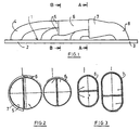
- the exhaust manifold shown in Fig. 1 includes a flange 1 which in its left part in Fig. 1, which is about two thirds of the total length extends as a cylinder flange 2 is formed. In his mind of it right adjoining Part of the flange 1 is then designed as a collecting flange 3.
- Starting from the cylinder flange 2 are three cylinder tubes 4 attached to the flange, for example by welding. Each cylinder tube 4 has an opening in the cylinder flange 2 in connection so that the through the opening of the Flange 2 passing gas jet through the corresponding Cylinder tube 4 is derived.
- the cylinder tubes 4 are approximately on the cylinder flange 2 attached at right angles and extend from there on over a quarter arch in one direction that essentially parallel or slightly oblique to the surface of the flange 1 runs.
- the first cylinder tube on the far left in FIG. 1, extends to beyond the second cylinder tube 4, the two first cylinder tubes 4 abut each other and in their End regions 5 run parallel to each other. Both end areas 5 of the first two cylinder tubes 4 are in an intermediate header tube 6 inserted, the axis of which is the same direction has as the end regions 5 of the cylinder tubes 4. It occurs So in the intermediate header 6 no deflection of the two the two cylinder tubes 4 emerging gas jets.
- the intermediate header 6 then continues approximately straight up to the also coaxially aligned manifold 7th
- the third cylinder tube 4 which also has a quarter arc is curved, is parallel in its end region to the end region of the intermediate header 6 and lies with his wall on this. It is next to the intermediate header 6 inserted horizontally into the end of the collecting tube 7, so that both the gas jet emerging from the intermediate header 6 as well as the gas jet from the cylinder tube 4 when entering run parallel to each other in the collecting tube 7.
- the Collecting tube 7 now picks up and directs all gas jets over the sheet 8 at its end to the as Collective flange acting part 3 of the flange.
- an outer shell for example in the form of a hood, arranged around with the flange 1 is welded gas-tight.
- Fig. 2 shows in its right half a section through the Arrangement of Fig. 1 along the line B-B, i.e. H. at the Point at which the end regions 5 of the two cylinder tubes 4 into the intermediate collecting tube with a circular cross-section open out.
- the cross section of the two end regions 5 corresponds to a semicircle, with a flat one Partition between the two walls that are close together issue.
- the intermediate header 6 is a close fit created around the two end regions 5.
- Both end areas 5 of the first two cylinder tubes 4 have the same Cross-sectional shape and the same cross-sectional size. From there the same amount of gas flows out of both cylinder tubes this way an equal speed of the two Gas flows reached when entering the intermediate header 6.
- Fig. 2 shows on the left a cross section through the arrangement along the line A-A.
- the end region 5 opens at this point of the third cylinder tube 4 together with the end region of the Intermediate header tube 6 in the header tube 7.
- the End region of the intermediate header tube 6 along a plane Partition surface at the end region of the third cylinder tube 4.
- the cross section of the intermediate header tube 6 is approximately twice as large as the cross section of the cylinder tube 4 since from the intermediate header 6 the gas flow from the two first cylinder tubes 4 emerges.
- FIG. 3 shows corresponding representations in an exhaust system, in which both the header pipe and the intermediate header pipe 6 has an oval cross section.
- Fig. 4 shows a longitudinal section through part of a Arrangement on an enlarged scale.
- the cylinder flange 2 has a plurality of openings 10 already mentioned, from which the exhaust gases from the internal combustion engine escape.
- every opening 10 is the end of a cylinder tube 4 assigned to the engine used and welded.
- the opposite ends 5 of the first two cylinder tubes 4 are in the intermediate header 6 inserted.
- the two ends 5 of the first two Cylinder tubes 4 are neither with each other nor with the intermediate header 6 welded or soldered, so that due to the Eliminating such a connection further reduced costs can be.
- the first cylinder tube 4 contains just before its end portion 5 has an outward projection Shape of a bead 11, for example, over a Extends part of its circumference.
- the intermediate header 6 together with the third cylinder tube 4 in the manifold 7 inserted.
- the intermediate header pipe 6 contains the intermediate header pipe 6 a bead 12 corresponding to the bead 11 Distance of the bead 12 from the associated end edge of the Intermediate manifold 6 is chosen so that thermal stresses can be included.
- the two beads 11, 12 are intended to prevent the intermediate collecting tube from slipping off 7 for temperature changes and for Prevent vibrations.
- Fig. 6 shows again the arrangement of Fig. 1, this time an outer shell 13 is broken off at the ends of the flange 1 is shown, along the edge of the flange 1 with this is welded.
- the flange 13 can also have holes 14, which have corresponding connection holes 15 of flange 1 match.
Abstract
Description
Die Erfindung geht aus von einem luftspaltisolierten Abgaskrümmer für Verbrennungsmotoren nach dem Oberbegriff von Anspruch 1.The invention is based on an air-gap-insulated exhaust manifold for Internal combustion engines according to the preamble of claim 1.
Es ist bislang üblich, daß derartige Abgaskrümmer ein Sammelrohr aufweisen, das grob gesprochen parallel oder in Längsrichtung des eben ausgebildeten Zylinderflanschs verläuft. Die von dem Zylinderflansch kommenden Zylinderrohre werden dann mit den Rändern von Öffnungen in dem Sammelrohr verbunden, so daß die Längsrichtung der Zylinderrohre mit der Längsrichtung des Sammelrohrs einen im wesentlichen rechten Winkel einschließt. Zur Verbesserung des Strömungsverhaltens ist es schon versucht worden, die Zylinderrohre leicht gekrümmt auszubilden, so daß sie schräg in das Sammelrohr einmünden.It has so far been customary for such exhaust manifolds to have a manifold, the roughly speaking parallel or in the longitudinal direction of the just trained Cylinder flange runs. The coming from the cylinder flange Cylinder tubes are then in with the edges of openings connected to the manifold so that the longitudinal direction of the cylinder tubes with the longitudinal direction of the manifold a substantially right Includes angle. It is to improve the flow behavior attempts have been made to make the cylinder tubes slightly curved, so that they open diagonally into the collecting pipe.
Zur Verbindung ist es möglich, das anzubindende Zylinderrohr mit einem Kragen zu versehen, der mittels einer Schweißnaht mit dem Rohr verbunden wird.For connection, it is possible to connect the cylinder tube to a To provide a collar that is connected to the tube by means of a weld seam becomes.
Diese Lösung hat den Nachteil, daß ein hoher Fertigungsaufwand durch Herstellen der Löcher in den Rohren, das Anpassen des Kragens an dem Rohr und durch die Schweißnähte betrieben werden muß. Da der angeschweißte Kragen der Dehnungsrichtung des Sammelrohrs entgegensteht, treten auch Risse auf. Das Eintreten des Gases aus dem Zylinderrohr unter einem Winkel gegenüber der Längsachse führt dazu, daß das heiße Gas die gegenüberliegende Wandung beaufschlagt, so daß es dort zu erhöhten Temperaturen, gegebenenfalls zum Lochausbrand kommt. Außerdem wird durch das schräge Einströmen eine Verwirbelung erzeugt, die sich nachteilig auf die optimale Gasgeschwindigkeit auswirkt.This solution has the disadvantage that a high manufacturing cost Making the holes in the pipes, fitting the collar to the Pipe and through the welds must be operated. Because the welded on Collar opposes the direction of expansion of the collecting tube, cracks also appear. Entry of gas from the cylinder barrel at an angle to the longitudinal axis causes the hot Gas acts on the opposite wall, causing it to rise there Temperatures, possibly leading to hole burnout. Moreover is created by the oblique inflow, the adversely affects the optimal gas velocity.
Es ist bereits ein luftspaltisolierter Abgaskrümmer mit den Merkmalen des ersten Teils des Anspruchs 1 bekannt (DE-A-42 26 171).It is already an air gap insulated exhaust manifold with the features of the first part of claim 1 known (DE-A-42 26 171).
Weiterhin ist es bekannt, bei Verbrennungsmotoren die Enden von selbsttragenden Auspuffrohren parallel zueinander und aneinander anliegend anzuordnen. Damit soll erreicht werden, daß die aus den einzelnen Zylinderrohren stammenden Gasimpulse zu unterschiedlichen Zeiten in ein weiterführendes Abgasrohr führen (WO 92-03639).Furthermore, it is known that the ends of self-supporting exhaust pipes parallel to and adjacent to each other to arrange. This is to ensure that the individual Gas pulses originating from cylinder tubes at different times in lead a further exhaust pipe (WO 92-03639).
Der Erfindung liegt die Aufgabe zugrunde, einen in strömungstechnischer und herstellungstechnischer Hinsicht verbesserten Abgaskrümmer zu schaffen.The invention has for its object one in fluidic and manufacturing technology improved exhaust manifold create.
Zur Lösung dieser Aufgabe schlägt die Erfindung einen Krümmer mit den im Anspruch 1 genannten Merkmalen vor. Weiterbildungen der Erfindung sind Gegenstand von Unteransprüchen.To achieve this object, the invention proposes a manifold with features mentioned in claim 1. Developments of the invention are the subject of subclaims.
Die Erfindung schlägt also vor, daß in einem Fall mit drei Zylinderrohren vorgesehen ist, daß zunächst die zwei ersten Zylinderrohre parallel zusammengeführt sind und mit einem axial ausgerichteten Zwischensammelrohr verbunden werden. Dieses Zwischensammelrohr kann dann mit dem dritten Zylinderrohr wiederum parallel ausgerichtet und zusammengeführt werden, wobei dann eine Verbindung, beispielsweise durch Einstecken, mit dem in gleicher Richtung verlaufenden Sammelrohr erfolgt. In diesem Fall erhält bei der Zusammenführung des Zwischensammelrohrs mit dem dritten Zylinderrohr das Zwischensammelrohr einen doppelt so großen Querschnitt wie das Zylinderrohr, da es ja die Gasströmung aus zwei Zylinderrohren aufnehmen soll.The invention therefore proposes that in a case with three cylinder tubes it is provided that the first two cylinder tubes are brought together in parallel are and with an axially aligned intermediate header get connected. This intermediate header pipe can then be used the third cylinder tube in turn aligned and merged then a connection, for example by plugging in, with the header pipe running in the same direction. In this case, when the intermediate manifold is brought together with the third cylinder tube the intermediate manifold a double as large a cross section as the cylinder tube since it is the gas flow from two cylinder tubes.
Entsprechend kann auch bei der Zusammenführung von vier oder mehr Zylinderrohren vorgegangen werden.Similarly, when four or more are merged Cylinder tubes are proceeded.
Bei der eingangs genannten Konstellation, wo also die Längsrichtung des Sammelrohrs quer zu den Richtungen der an dem Zylinderflansch angebrachten Zylinderrohre steht, werden die ersten beiden Zylinderrohre so geformt, daß sie in ihrem Endbereich die Richtung des Zwischensammelrohrs aufweisen. Diese Krümmung, beispielsweise um 90°, kann dabei so erfolgen, daß eine allmähliche Umlenkung des Gasstrahls bewirkt wird. In ihrem Endbereich, wenn also das Gas in das Zwischensammelrohr strömt, haben die Gase schon die gleiche Richtung wie das Zwischensammelrohr, so daß keine einseitigen lokalen Beaufschlagungen von Wandteilen auftreten. Das Einbringen von Löchern in die Wand des Zwischensammelrohrs entfällt, da die beiden ersten Zylinderrohre axial in das dort sowieso geöffnete Zwischensammelrohr eingesteckt bzw. mit diesem verbunden werden.In the constellation mentioned above, where the longitudinal direction of the Manifold transverse to the directions of those attached to the cylinder flange The first two cylinder tubes are like this shaped so that in its end region the direction of the intermediate header exhibit. This curvature, for example by 90 °, can be so take place that a gradual deflection of the gas jet is effected. In its end area, that is, when the gas flows into the intermediate manifold, the gases are already in the same direction as the intermediate manifold, so that there are no one-sided local impacts on wall parts. The making of holes in the wall of the intermediate header omitted, since the first two cylinder tubes axially in there anyway Opened intermediate header pipe inserted or connected to it become.
Da die Gasströme beim Austreten aus den beiden ersten Zylinderrohren und beim Eintritt in das Zwischensammelrohr bereits parallel zueinander ausgerichtet sind, tritt auch das Problem der gegenseitigen Behinderung der Gasströme nicht mehr auf. Dies führt zu einer Verbesserung der Motorcharakteristik. Es kann durch Querschnittsauswahl dafür gesorgt werden, daß die Strömungsgeschwindigkeit der beiden Gasströme beim Verlassen der Zylinderrohre gleich ist. Entsprechendes gilt für das dritte und eventuelle weitere Zylinderrohre.Because the gas flows when exiting the first two cylinder tubes and already parallel to each other when entering the intermediate header the problem of mutual disability also arises the gas flows no longer. This leads to an improvement in the engine characteristics. Cross-sectional selection can ensure that that the flow rate of the two gas flows when leaving the cylinder tubes are the same. The same applies to the third and possible further cylinder tubes.
In Weiterbildung der Erfindung kann vorgesehen sein, daß die aneinander anliegenden zusammengeführten Enden der Zylinderrohre längs einer insbesondere ebenen Fläche aneinander anliegen.In a development of the invention it can be provided that the one another adjacent merged ends of the cylinder tubes along one especially abut a flat surface.
Die Erfindung schlägt vor, daß der Querschnitt durch die zusammengeführten Enden der beiden ersten Zylinderrohre jeweils einem Halbkreis, einem Halboval oder einer sonstigen Halbform entsprechen kann. Wenn beispielsweise das Zwischensammelrohr einen kreisförmigen Querschnitt aufweist, enthalten die beiden ersten Zylinderrohre in ihrem Endbereich einen halbkreisförmigen Querschnitt. Bei einem oval ausgeführten Zwischensammelrohr würde der Querschnitt dementsprechend die Form eines halben Ovals haben.The invention proposes that the cross section through the merged Ends of the first two cylinder tubes each with a semicircle, can correspond to a semi-oval or another semi-shape. If for example, the intermediate header pipe has a circular cross section has, contain the first two cylinder tubes in their end region a semicircular cross section. With an oval intermediate header pipe the cross section would accordingly have the shape of a have half oval.
Erfindungsgemäß kann vorgesehen sein, daß die Zwischensammelrohre durch Ansätze, Ausbeulungen oder Vorsprünge gegen ein Verrutschen gesichert werden, wobei diese so angeordnet sind, daß Temperaturdehnungen noch möglich sind.According to the invention it can be provided that the intermediate header pipes secured against slipping by lugs, bulges or projections be, these are arranged so that temperature expansions are still possible.
Die von der Erfindung vorgeschlagene parallele Ausrichtung der zusammengeführten Enden von Zylinderrohren ist insbesondere bei luftspaltisolierten Abgaskrümmern anwendbar, bei denen das gasführende Innenrohrsystem innerhalb einer Außenschale angeordnet ist, die mit dem Zylinderflansch und dem Sammelflansch verbunden, insbesondere verschweißt ist. In diesem Fall kann die Verbindung zwischen den Zylinderrohren, dem Sammelrohr und den Zwischensammelrohren durch einfaches Stecken erfolgen, da eine Gasdichtheit nicht mehr erforderlich ist. Durch entsprechende Formgebung und enges Anliegen der einzelnen Teile aneinander kann dafür gesorgt werden, daß die Undichtigkeit klein gehalten wird.The proposed parallel alignment of the merged by the invention End of cylinder tubes is especially in the case of air gap insulated Exhaust manifolds applicable in which the gas-bearing inner pipe system is arranged within an outer shell, which with the cylinder flange and connected to the collecting flange, in particular welded is. In this case, the connection between the cylinder tubes, the manifold and the intermediate manifolds by simple Plug in because gas tightness is no longer required. By appropriate shaping and tight fitting of the individual parts together, it can be ensured that the leakage is kept small becomes.
Weitere Merkmale, Einzelheiten und Vorzüge ergeben sich aus den Patentansprüchen, deren Wortlaut durch Bezugnahme zum Inhalt der Beschreibung gemacht wird, der folgenden Beschreibung einer bevorzugten Ausführungsform der Erfindung sowie anhand der Zeichnung. Hierbei zeigen:
- Fig. 1
- eine schematische Seitenansicht eines Abgaskrümmers, bei dem der Zylinderflansch einstückig in einen Sammelflansch übergeht;
- Fig. 2
- Querschnitte durch die Anordnung der Fig. 1 an zwei Stellen;
- Fig. 3
- Querschnitte durch eine ähnliche Anordnung bei einer anderen Außenform;
- Fig. 4
- einen Teillängsschnitt durch einen Abgaskrümmer mit drei Zylinderrohren;
- Fig. 5
- einen Längsschnitt durch den Abgaskrümmer der Fig. 1.
- Fig. 1
- is a schematic side view of an exhaust manifold, in which the cylinder flange integrally merges into a collecting flange;
- Fig. 2
- Cross sections through the arrangement of Figure 1 in two places.
- Fig. 3
- Cross sections through a similar arrangement with a different outer shape;
- Fig. 4
- a partial longitudinal section through an exhaust manifold with three cylinder tubes;
- Fig. 5
- 2 shows a longitudinal section through the exhaust manifold of FIG. 1.
Der in Fig. 1 dargestellte Abgaskrümmer enthält einen Flansch 1, der in
seinem in Fig. 1 linken Teil, der sich über etwa zwei Drittel der Gesamtlänge
erstreckt, als Zylinderflansch 2 ausgebildet ist. In seinem sich daran
rechts anschließenden
Teil ist der Flansch 1 dann als Sammelflansch 3 ausgebildet.
Von dem Zylinderflansch 2 ausgehend sind drei Zylinderrohre 4
an dem Flansch befestigt, beispielsweise durch Schweißen.
Jedes Zylinderrohr 4 steht mit einer Öffnung in dem Zylinderflansch
2 in Verbindung, so daß der durch die Öffnung des
Flanschs 2 durchtretende Gasstrahl durch das entsprechende
Zylinderrohr 4 abgeleitet wird.The exhaust manifold shown in Fig. 1 includes a flange 1 which in
its left part in Fig. 1, which is about two thirds of the total length
extends as a
Die Zylinderrohre 4 sind am Zylinderflansch 2 etwa unter
einem rechten Winkel angebracht und erstrecken sich von dort
an über einen Viertelbogen in eine Richtung, die im wesentlichen
parallel oder leicht schräg zu der Fläche des Flanschs 1
verläuft.The
Das erste Zylinderrohr, in Fig. 1 ganz links, erstreckt sich
bis über das zweite Zylinderrohr 4 hinaus, wobei die beiden
ersten Zylinderrohre 4 aneinander anliegen und in ihren
Endbereichen 5 parallel zueinander verlaufen. Beide Endbereiche
5 der beiden ersten Zylinderrohre 4 sind in ein Zwischensammelrohr
6 hineingeführt, dessen Achse die gleiche Richtung
aufweist wie die Endbereiche 5 der Zylinderrohre 4. Es tritt
also im Zwischensammelrohr 6 keine Umlenkung der beiden aus
den beiden Zylinderrohren 4 austretenden Gasstrahlen auf.The first cylinder tube, on the far left in FIG. 1, extends
to beyond the
Das Zwischensammelrohr 6 verläuft dann etwa geradlinig weiter
bis zu dem ebenfalls gleichachsig ausgerichteten Sammelrohr
7.The
Das dritte Zylinderrohr 4, das ebenfalls über einen Viertelkreisbogen
gebogen verläuft, ist in seinem Endbereich parallel
zu dem Endbereich des Zwischensammelrohrs 6 und liegt mit
seiner Wand an diesem an. Es ist neben dem Zwischensammelrohr
6 liegend in das Ende des Sammelrohrs 7 eingesteckt, so daß
sowohl der aus dem Zwischensammelrohr 6 austretende Gasstrahl
als auch der Gasstrahl aus dem Zylinderrohr 4 beim Eintreten
in das Sammelrohr 7 parallel zueinander verlaufen. Das
Sammelrohr 7 nimmt nun alle Gasstrahlen auf und lenkt sie
über den an seinem Ende vorhandenen Bogen 8 zu dem als
Sammelflansch wirkenden Teil 3 des Flanschs um.The
Bei einem Abgaskrümmer für einen Verbrennungsmotor wird um die in Fig. 1 zu sehende Rohranordnung eine Außenschale, beispielsweise in Form einer Haube, herum angeordnet, die mit dem Flansch 1 gasdicht verschweißt ist.At an exhaust manifold for an internal combustion engine is around 1 can be seen an outer shell, for example in the form of a hood, arranged around with the flange 1 is welded gas-tight.
Fig. 2 zeigt in seiner rechten Hälfte einen Schnitt durch die
Anordnung der Fig. 1 längs der Linie B-B, d. h. an der
Stelle, an der die Endbereiche 5 der beiden Zylinderrohre 4
in das mit kreisrundem Querschnitt versehene Zwischensammelrohr
einmünden. Der Querschnitt der beiden Endbereiche 5
entspricht einem Halbkreis, mit einer eben verlaufenden
Trennfläche zwischen den beiden Wänden, die dicht aneinander
anliegen. Das Zwischensammelrohr 6 ist mit enger Passung
um die beiden Endbereiche 5 herum angelegt. Beide Endbereiche
5 der beiden ersten Zylinderrohre 4 besitzen die gleiche
Querschnittsform und die gleiche Querschnittsgröße. Da aus
beiden Zylinderrohren die gleiche Gasmenge ausströmt, wird
auf diese Weise eine gleiche Geschwindigkeit der beiden
Gasströme beim Eintreten in das Zwischensammelrohr 6 erreicht.Fig. 2 shows in its right half a section through the
Arrangement of Fig. 1 along the line B-B, i.e. H. at the
Point at which the
Fig. 2 zeigt links einen Querschnitt durch die Anordnung
längs der Linie A-A. An dieser Stelle mündet der Endbereich 5
des dritten Zylinderrohrs 4 zusammen mit dem Endbereich des
Zwischensammelrohrs 6 in das Sammelrohr 7. Wiederum liegt der
Endbereich des Zwischensammelrohrs 6 längs einer ebenen
Trennfläche an dem Endbereich des dritten Zylinderrohrs 4 an.
Der Querschnitt des Zwischensammelrohrs 6 ist jedoch etwa
doppelt so groß wie der Querschnitt des Zylinderrohrs 4, da
aus dem Zwischensammelrohr 6 der Gasstrom aus den beiden
ersten Zylinderrohren 4 austritt.Fig. 2 shows on the left a cross section through the arrangement
along the line A-A. The
Fig. 3 zeigt entsprechende Darstellungen bei einem Abgassystem,
bei dem sowohl das Sammelrohr als auch das Zwischensammelrohr
6 einen ovalen Querschnitt aufweist.3 shows corresponding representations in an exhaust system,
in which both the header pipe and the
Fig. 4 zeigt einen Längsschnitt durch einen Teil einer
Anordnung in vergrößertem Maßstab. Der Zylinderflansch 2
weist mehrere bereits erwähnte Öffnungen 10 auf, aus denen
die Abgase des Verbrennungsmotors austreten. In jeder Öffnung
10 ist das dem Motor zugeordnete Ende eines Zylinderrohrs 4
eingesetzt und festgeschweißt. Die entgegengesetzten Enden 5
der beiden ersten Zylinderrohre 4 sind in das Zwischensammelrohr
6 eingesteckt. Die beiden Enden 5 der ersten beiden
Zylinderrohre 4 sind weder miteinander noch mit dem Zwischensammelrohr
6 verschweißt oder verlötet, so daß aufgrund des
Wegfalls einer solchen Verbindung die Kosten weiter gesenkt
werden können. Das erste Zylinderrohr 4 enthält kurz vor
seinem Endbereich 5 einen nach außen gerichteten Vorsprung in
Form eines Wulstes 11, der sich beispielsweise über einen
Teil seines Umfangs erstreckt.Fig. 4 shows a longitudinal section through part of a
Arrangement on an enlarged scale. The
Am gegenüberliegenden Ende ist das Zwischensammelrohr 6
zusammen mit dem an ihm anliegenden dritten Zylinderrohr 4 in
das Sammelrohr 7 eingesteckt. Hier enthält das Zwischensammelrohr
6 einen dem Wulst 11 entsprechenden Wulst 12. Der
Abstand des Wulstes 12 von der zugeordneten Endkante des
Zwischensammelrohrs 6 ist so gewählt, daß Wärmespannungen
aufgenommen werden können.At the opposite end is the
Die beiden Wulste 11, 12 sollen ein Abrutschen des Zwischensammelrohrs
7 bei Temperaturwechselbeanspruchung und bei
Erschütterungen verhindern.The two
Wie der Fig. 4 zu entnehmen ist, reichen die Enden 5 der
Zylinderrohre 4 bzw. der Endbereich des Zwischensammelrohrs 6
um eine relativ kurze Strecke in das jeweils nachfolgende
Bauteil hinein. Die Anordnung ist so gewählt, daß jedes
gasführende Rohrelement innen in das nachfolgende Rohrelement
hineingesteckt ist. Die beiden zusammengeführten Enden 5 der
beiden ersten Zylinderrohre 4 enden in der gleichen Ebene,
ebenso wie das dritte Zylinderrohr 4 und das Zwischensammelrohr
6.4, the
Fig. 6 zeigt nochmals die Anordnung der Fig. 1, wobei diesmal
an den Enden des Flanschs 1 abgebrochen eine Außenschale 13
dargestellt ist, die längs des Rands des Flanschs 1 mit
diesem verschweißt ist. Der Flansch 13 kann ebenfalls Löcher
14 aufweisen, die mit entsprechenden Verbindungslöchern 15
des Flanschs 1 übereinstimmen.Fig. 6 shows again the arrangement of Fig. 1, this time
an
Claims (7)
- An air gap insulated exhaust manifold having a cylinder head flange (2) for the attachment of the manifold to a cylinder head, having a manifold flange (3) for the connection of a manifold outlet pipe, having an outer shell (13), which is connected to the cylinder head flange (2) and to the manifold flange (3), and having a gas conducting inner pipe system within the outer shell (13), which has a collecting pipe (7) connected to the manifold flange (3) and at least three primary pipes (4) connected to the cylinder head flange (2), characterised in that
the ends (5) of the first two primary pipes (4) extend parallel to one another;
are arranged contacting one another and are connected to, in particular inserted into, an axially oriented intermediate collecting pipe (6) which, with the third primary pipe (4), is in turn arranged extending parallel to one another in the end region, and contacting one another and being joined together in the end region and connected to, in particular inserted into, the collecting pipe (7), or to a further intermediate collecting pipe. - An exhaust manifold in accordance with claim 1, wherein the ends (5) of the primary pipes (4) contacting one another and being led together contact one another along a surface, in particular a planar surface.
- An exhaust manifold in accordance with claim 1 or claim 2, wherein the cross-section through the ends (5) of the two first primary pipes (4), which are led together, corresponds in each case to a semi-circle or a semi-oval.
- An exhaust manifold in accordance with any one of the preceding claims, wherein the intermediate collecting pipes (6) are held between projections (11, 12) or bulges.
- An exhaust manifold in accordance with any one of the preceding claims, wherein the collecting pipe (7) and/or the intermediate collecting pipes (6) have a cross-section corresponding to the common cross-section of the primary pipes (4) which are led together.
- An exhaust manifold in accordance with any one of the preceding claims, wherein the cross-sectional partitioning of the intermediate collecting pipes (6) and/or of the collecting pipe (7) corresponds to the number of primary pipes (4) which are led together.
- An exhaust manifold in accordance with any one of the preceding claims, wherein the primary pipes (4), the collecting pipe (7) and the intermediate collecting pipes (6) are connected to one another by insertion.
Applications Claiming Priority (2)
| Application Number | Priority Date | Filing Date | Title |
|---|---|---|---|
| DE19507439 | 1995-03-03 | ||
| DE19507439A DE19507439A1 (en) | 1995-03-03 | 1995-03-03 | Exhaust manifold |
Publications (2)
| Publication Number | Publication Date |
|---|---|
| EP0731258A1 EP0731258A1 (en) | 1996-09-11 |
| EP0731258B1 true EP0731258B1 (en) | 2002-09-04 |
Family
ID=7755538
Family Applications (1)
| Application Number | Title | Priority Date | Filing Date |
|---|---|---|---|
| EP96102547A Expired - Lifetime EP0731258B1 (en) | 1995-03-03 | 1996-02-21 | Exhaust manifold |
Country Status (4)
| Country | Link |
|---|---|
| EP (1) | EP0731258B1 (en) |
| AT (1) | ATE223556T1 (en) |
| DE (2) | DE19507439A1 (en) |
| ES (1) | ES2178683T3 (en) |
Cited By (1)
| Publication number | Priority date | Publication date | Assignee | Title |
|---|---|---|---|---|
| DE19917604C5 (en) * | 1998-04-20 | 2009-09-10 | Honda Giken Kogyo K.K. | Heat insulated exhaust manifold |
Families Citing this family (7)
| Publication number | Priority date | Publication date | Assignee | Title |
|---|---|---|---|---|
| DE19957979B4 (en) * | 1999-12-02 | 2006-08-10 | Audi Ag | exhaust manifold |
| DE10219269A1 (en) * | 2002-04-30 | 2003-11-20 | Zeuna Staerker Kg | Double-shell, air-gap insulated exhaust gas merging and method for their production |
| DE10261879B4 (en) * | 2002-12-20 | 2012-09-27 | Volkswagen Ag | Exhaust manifold |
| DE602004012167T3 (en) | 2003-12-01 | 2018-08-16 | Nissan Motor Co., Ltd. | Exhaust manifold for an internal combustion engine |
| DE102009001542A1 (en) | 2009-03-13 | 2010-10-07 | Ford Global Technologies, LLC, Dearborn | Cylinder head for a naturally aspirated engine and use of such a cylinder head |
| USD812100S1 (en) | 2015-03-31 | 2018-03-06 | Litchfield Imports Limited | Exhaust manifold |
| CN114135380B (en) * | 2022-01-27 | 2023-01-06 | 潍柴动力股份有限公司 | Exhaust manifold |
Family Cites Families (8)
| Publication number | Priority date | Publication date | Assignee | Title |
|---|---|---|---|---|
| US2344863A (en) * | 1942-04-09 | 1944-03-21 | Continental Motors Corp | Internal combustion engine |
| US3043094A (en) * | 1960-02-29 | 1962-07-10 | Alco Products Inc | Exhaust manifolds |
| JPH01138311A (en) * | 1987-11-24 | 1989-05-31 | Mazda Motor Corp | Exhaust passage structure of engine |
| ATE163991T1 (en) * | 1990-08-13 | 1998-03-15 | Flowmaster Inc | COLLECTION PIPE SYSTEM FOR INTERNAL COMBUSTION ENGINE AND PROCESS |
| JP2632601B2 (en) * | 1991-02-18 | 1997-07-23 | 株式会社ユタカ技研 | Exhaust pipe |
| DE4226171A1 (en) * | 1992-08-07 | 1994-02-10 | Bischoff Erhardt Gmbh Co Kg | Exhaust manifold |
| US5299419A (en) * | 1992-11-02 | 1994-04-05 | Bittle James J | Gas flow headers for internal combustion engines |
| DE4342572C1 (en) * | 1993-12-14 | 1994-11-24 | Mtu Friedrichshafen Gmbh | Exhaust system for a turbocharged internal combustion engine |
-
1995
- 1995-03-03 DE DE19507439A patent/DE19507439A1/en not_active Withdrawn
-
1996
- 1996-02-21 DE DE59609613T patent/DE59609613D1/en not_active Expired - Lifetime
- 1996-02-21 EP EP96102547A patent/EP0731258B1/en not_active Expired - Lifetime
- 1996-02-21 AT AT96102547T patent/ATE223556T1/en not_active IP Right Cessation
- 1996-02-21 ES ES96102547T patent/ES2178683T3/en not_active Expired - Lifetime
Cited By (1)
| Publication number | Priority date | Publication date | Assignee | Title |
|---|---|---|---|---|
| DE19917604C5 (en) * | 1998-04-20 | 2009-09-10 | Honda Giken Kogyo K.K. | Heat insulated exhaust manifold |
Also Published As
| Publication number | Publication date |
|---|---|
| DE19507439A1 (en) | 1996-09-05 |
| DE59609613D1 (en) | 2002-10-10 |
| EP0731258A1 (en) | 1996-09-11 |
| ES2178683T3 (en) | 2003-01-01 |
| ATE223556T1 (en) | 2002-09-15 |
Similar Documents
| Publication | Publication Date | Title |
|---|---|---|
| EP0735251B1 (en) | Exhaust collector for an internal combustion engine | |
| EP0737803B1 (en) | Exhaust collector, particularly for an internal combustion engine in a motor vehicle, and process for its manufacture | |
| EP0582985A1 (en) | Exhaust manifold | |
| DE2033434A1 (en) | Exhaust collector | |
| DE69915994T2 (en) | Cross-flow silencer with baffles | |
| DE19819946A1 (en) | Exhaust manifold | |
| EP0731258B1 (en) | Exhaust manifold | |
| DE2238256B2 (en) | Exhaust collector for an internal combustion engine | |
| EP0023041A1 (en) | External housing for an internal combustion engine silencer | |
| DE10045499B4 (en) | Exhaust system for a motorcycle | |
| DE19523532A1 (en) | Catalytic converter arrangement with two or more-strand exhaust gas routing | |
| DE19508217A1 (en) | Metallic honeycomb body | |
| EP2921670A2 (en) | Exhaust manifold for an exhaust system of a combustion engine | |
| DE102004018693B4 (en) | exhaust system | |
| DE10144015A1 (en) | Exhaust system for multi-cylinder internal combustion engines | |
| EP1367234B1 (en) | Double wall exhaust pipe with flange | |
| DE102008018668B4 (en) | Exhaust manifold and exhaust pipe for internal combustion engines | |
| DE19952648C2 (en) | Air gap insulated cup manifold | |
| DE19526084A1 (en) | Exhaust manifold | |
| EP1199450A2 (en) | Exhaust manifold | |
| DE112004000717B4 (en) | Organ of an exhaust pipe of a motor vehicle | |
| EP0451662B1 (en) | Recuperative burner | |
| DE4316870A1 (en) | Device for purifying exhaust gases from an internal combustion engine and a method for its manufacture | |
| DE19832627A1 (en) | Device for blowing secondary air into exhaust gas area of internal combustion engine has flange for exhaust gas pipe fitted to cylinder head and air feed conduit connected to flange | |
| DE10359073A1 (en) | Exhaust manifold for internal combustion engine, has feather seal arranged between gas conducting body and flange so that temperature conditional expansion takes place relative to flange, where body moves relative to flange with expansion |
Legal Events
| Date | Code | Title | Description |
|---|---|---|---|
| PUAI | Public reference made under article 153(3) epc to a published international application that has entered the european phase |
Free format text: ORIGINAL CODE: 0009012 |
|
| AK | Designated contracting states |
Kind code of ref document: A1 Designated state(s): AT BE DE ES FR GB IT SE |
|
| 17P | Request for examination filed |
Effective date: 19970226 |
|
| 17Q | First examination report despatched |
Effective date: 19980921 |
|
| RAP1 | Party data changed (applicant data changed or rights of an application transferred) |
Owner name: FRIEDRICH BOYSEN GMBH & CO. KG |
|
| GRAG | Despatch of communication of intention to grant |
Free format text: ORIGINAL CODE: EPIDOS AGRA |
|
| GRAG | Despatch of communication of intention to grant |
Free format text: ORIGINAL CODE: EPIDOS AGRA |
|
| GRAH | Despatch of communication of intention to grant a patent |
Free format text: ORIGINAL CODE: EPIDOS IGRA |
|
| GRAH | Despatch of communication of intention to grant a patent |
Free format text: ORIGINAL CODE: EPIDOS IGRA |
|
| GRAA | (expected) grant |
Free format text: ORIGINAL CODE: 0009210 |
|
| AK | Designated contracting states |
Kind code of ref document: B1 Designated state(s): AT BE DE ES FR GB IT SE |
|
| REF | Corresponds to: |
Ref document number: 223556 Country of ref document: AT Date of ref document: 20020915 Kind code of ref document: T |
|
| REG | Reference to a national code |
Ref country code: GB Ref legal event code: FG4D Free format text: NOT ENGLISH |
|
| REF | Corresponds to: |
Ref document number: 59609613 Country of ref document: DE Date of ref document: 20021010 |
|
| GBT | Gb: translation of ep patent filed (gb section 77(6)(a)/1977) |
Effective date: 20021014 |
|
| ET | Fr: translation filed | ||
| REG | Reference to a national code |
Ref country code: ES Ref legal event code: FG2A Ref document number: 2178683 Country of ref document: ES Kind code of ref document: T3 |
|
| PLBE | No opposition filed within time limit |
Free format text: ORIGINAL CODE: 0009261 |
|
| STAA | Information on the status of an ep patent application or granted ep patent |
Free format text: STATUS: NO OPPOSITION FILED WITHIN TIME LIMIT |
|
| 26N | No opposition filed |
Effective date: 20030605 |
|
| PGFP | Annual fee paid to national office [announced via postgrant information from national office to epo] |
Ref country code: ES Payment date: 20090219 Year of fee payment: 14 Ref country code: AT Payment date: 20090218 Year of fee payment: 14 |
|
| PGFP | Annual fee paid to national office [announced via postgrant information from national office to epo] |
Ref country code: SE Payment date: 20090216 Year of fee payment: 14 Ref country code: IT Payment date: 20090221 Year of fee payment: 14 |
|
| PGFP | Annual fee paid to national office [announced via postgrant information from national office to epo] |
Ref country code: BE Payment date: 20090408 Year of fee payment: 14 |
|
| PGFP | Annual fee paid to national office [announced via postgrant information from national office to epo] |
Ref country code: FR Payment date: 20090213 Year of fee payment: 14 |
|
| PGFP | Annual fee paid to national office [announced via postgrant information from national office to epo] |
Ref country code: GB Payment date: 20100218 Year of fee payment: 15 |
|
| BERE | Be: lapsed |
Owner name: FRIEDRICH *BOYSEN G.M.B.H. & CO. K.G. Effective date: 20100228 |
|
| EUG | Se: european patent has lapsed | ||
| REG | Reference to a national code |
Ref country code: FR Ref legal event code: ST Effective date: 20101029 |
|
| PG25 | Lapsed in a contracting state [announced via postgrant information from national office to epo] |
Ref country code: AT Free format text: LAPSE BECAUSE OF NON-PAYMENT OF DUE FEES Effective date: 20100221 |
|
| PG25 | Lapsed in a contracting state [announced via postgrant information from national office to epo] |
Ref country code: FR Free format text: LAPSE BECAUSE OF NON-PAYMENT OF DUE FEES Effective date: 20100301 |
|
| PG25 | Lapsed in a contracting state [announced via postgrant information from national office to epo] |
Ref country code: BE Free format text: LAPSE BECAUSE OF NON-PAYMENT OF DUE FEES Effective date: 20100228 |
|
| REG | Reference to a national code |
Ref country code: ES Ref legal event code: FD2A Effective date: 20110324 |
|
| PG25 | Lapsed in a contracting state [announced via postgrant information from national office to epo] |
Ref country code: IT Free format text: LAPSE BECAUSE OF NON-PAYMENT OF DUE FEES Effective date: 20100221 |
|
| PG25 | Lapsed in a contracting state [announced via postgrant information from national office to epo] |
Ref country code: ES Free format text: LAPSE BECAUSE OF NON-PAYMENT OF DUE FEES Effective date: 20110310 |
|
| PG25 | Lapsed in a contracting state [announced via postgrant information from national office to epo] |
Ref country code: ES Free format text: LAPSE BECAUSE OF NON-PAYMENT OF DUE FEES Effective date: 20100222 |
|
| GBPC | Gb: european patent ceased through non-payment of renewal fee |
Effective date: 20110221 |
|
| PG25 | Lapsed in a contracting state [announced via postgrant information from national office to epo] |
Ref country code: GB Free format text: LAPSE BECAUSE OF NON-PAYMENT OF DUE FEES Effective date: 20110221 |
|
| PG25 | Lapsed in a contracting state [announced via postgrant information from national office to epo] |
Ref country code: SE Free format text: LAPSE BECAUSE OF NON-PAYMENT OF DUE FEES Effective date: 20100222 |
|
| PGFP | Annual fee paid to national office [announced via postgrant information from national office to epo] |
Ref country code: DE Payment date: 20150429 Year of fee payment: 20 |
|
| REG | Reference to a national code |
Ref country code: DE Ref legal event code: R071 Ref document number: 59609613 Country of ref document: DE |