EP0729003B1 - Plattenwärmeübertrager mit einer Umfangsdichtung - Google Patents
Plattenwärmeübertrager mit einer Umfangsdichtung Download PDFInfo
- Publication number
- EP0729003B1 EP0729003B1 EP95113150A EP95113150A EP0729003B1 EP 0729003 B1 EP0729003 B1 EP 0729003B1 EP 95113150 A EP95113150 A EP 95113150A EP 95113150 A EP95113150 A EP 95113150A EP 0729003 B1 EP0729003 B1 EP 0729003B1
- Authority
- EP
- European Patent Office
- Prior art keywords
- plate
- heat exchanger
- exchanger according
- rim
- projections
- Prior art date
- Legal status (The legal status is an assumption and is not a legal conclusion. Google has not performed a legal analysis and makes no representation as to the accuracy of the status listed.)
- Expired - Lifetime
Links
Images



Classifications
-
- F—MECHANICAL ENGINEERING; LIGHTING; HEATING; WEAPONS; BLASTING
- F28—HEAT EXCHANGE IN GENERAL
- F28F—DETAILS OF HEAT-EXCHANGE AND HEAT-TRANSFER APPARATUS, OF GENERAL APPLICATION
- F28F3/00—Plate-like or laminated elements; Assemblies of plate-like or laminated elements
- F28F3/08—Elements constructed for building-up into stacks, e.g. capable of being taken apart for cleaning
- F28F3/10—Arrangements for sealing the margins
-
- Y—GENERAL TAGGING OF NEW TECHNOLOGICAL DEVELOPMENTS; GENERAL TAGGING OF CROSS-SECTIONAL TECHNOLOGIES SPANNING OVER SEVERAL SECTIONS OF THE IPC; TECHNICAL SUBJECTS COVERED BY FORMER USPC CROSS-REFERENCE ART COLLECTIONS [XRACs] AND DIGESTS
- Y10—TECHNICAL SUBJECTS COVERED BY FORMER USPC
- Y10S—TECHNICAL SUBJECTS COVERED BY FORMER USPC CROSS-REFERENCE ART COLLECTIONS [XRACs] AND DIGESTS
- Y10S165/00—Heat exchange
- Y10S165/355—Heat exchange having separate flow passage for two distinct fluids
- Y10S165/356—Plural plates forming a stack providing flow passages therein
- Y10S165/364—Plural plates forming a stack providing flow passages therein with fluid traversing passages formed through the plate
- Y10S165/365—Plural plates forming a stack providing flow passages therein with fluid traversing passages formed through the plate including peripheral seal element forming flow channel bounded by seal and heat exchange plates
- Y10S165/369—Plural plates forming a stack providing flow passages therein with fluid traversing passages formed through the plate including peripheral seal element forming flow channel bounded by seal and heat exchange plates including seal to plate attachment means
Definitions
- the invention relates to a plate heat exchanger with a Intermediate space aligned heat exchanger plates as well a peripheral seal to complete the heat exchanger area
- Heat exchanger plates one of the plates one around the heat exchanger area has around extending groove for receiving the seal, along which substantially evenly distributed numerous projections parallel to the plates are formed with terminal fastening parts, which correspond to me Breakthroughs in the edge of one adjoining the groove Plate are engaged.
- seals To replace or replace the seals in the event of operational damage To be able to, the seals must be releasably connected to the plates.
- seals of the type mentioned above attach the fasteners releasably to the respective one plate.
- the fasteners formed as mushroom-shaped heads, which in the holes of Plate edge are pressed or buttoned (EP 0 039 229 A).
- the one with it associated work is time consuming and for the operator's hands exhausting.
- the object of the invention is therefore to provide a peripheral seal of the aforementioned Art to further train that they are much easier and can be installed faster and there is also the risk of external damage is withdrawn.
- the openings an edge of the plate edge are open.
- the edge be the outer edge of the plate edge.
- the conceivably simple measure according to the invention creates the possibility the fasteners from outside the edge of one plate into the now insert openings that are essentially U-shaped, which is a comparatively much simpler and less energy-intensive Work means. It has been shown that the assembly time for a seal is different using the subject matter of the invention to about a quarter leaves.
- the measure according to the invention ensures that when the seal is under the excess pressure in the space between the plates something is squeezed outwards, the fastening parts no longer cut through an edge that limits the opening to the outside or can even be sheared off.
- the projections are essentially are tabs extending perpendicular to the longitudinal course of the seal.
- the respective part forming the support for the projections the edge of one plate level with the bottom be the groove.
- the respective one forming the support for the projections Part of the edge of one plate opposite the Bottom of the groove is stepped up to allow the outer Groove wall also in the area of the projections none Experiencing interruption of their supportive effect.
- the fasteners can be from the rotating Spaced outer edge or inner edge of the seal arranged and perpendicular from the protrusions in Direction on which parts protrude a plate what for example, by designing the fastening parts than essentially cylindrical or related to theirs End widening cones can happen. It exists however, the possibility that the fasteners forming a neck terminal, based on the Projections beyond the head-like sitting one plate Have extensions. The neck is then from that Edge of the openings covers and prevent it head-like extensions an unwanted slipping out the fastening parts from the openings.
- the fasteners can be transverse its longitudinal extension is circular, elliptical or have a polygonal cross section.
- the fasteners transverse to their longitudinal extension an elongated, essentially up to the outer edge of the plate edge have going cross-section, ie essentially U-shaped openings in the plate edge practical fill out, resulting in an even more stable fit the fastening parts within the one plate results.
- the openings in the area of the edge of the plate edge have funnel-shaped extension through which the Thread the fasteners into the openings is facilitated.
- At least two adjacent ones Projections at the end through a fastening part are connected to each other in the form of a bridge, and that the bridge proceeding from the ledges assigned openings related to the projections is arranged beyond the one plate.
- the bridge therefore engages under the plate edge starting from the Ends of the protrusions. It subsides because of open openings of the openings also easy to assemble, but is now not outside of the plate pack is free and therefore there is no risk of damage exposed.
- the one under attack by the bridge Section of the plate edge opposite the neighboring one Sections towards the bridge is offset to an excessive kinking of the Seal forming material in the neck area between Avoid protrusions and bridge.
- the same could be through an appropriately stepped approach to the bridge can be reached on the projections, the aforementioned
- preference is given to possible solutions.
- the bridge perpendicular to the surface of one plate opposite the projections have a lower material thickness.
- it is also advisable that the openings in the longitudinal direction of the plate edge widened compared to the dimensions of the projections are trained.
- Figure 1 shows the top view of a heat exchanger plate 1 for example made of stainless steel sheet, the in the heat exchange area with embossed profiles 2 is provided.
- the heat exchange range is from a circumferential seal 3, which is still in a descriptive, embossed into the plate 1, circumferential Groove sits.
- the seal 3 faces outwards Projections 4 on which they are still in to be described detachably connected to the plate 1 is. Openings also encompassed by the seal 3 5, 6, 7, 8 serve the line in a known manner the one subject to mutual heat exchange Media.
- FIG. 1 now shows together with those taken from it Section according to Figures 3 and 4 in an enlarged view section A from FIG. 1. It can be seen here that the seal 3 is stamped into the plate, groove surrounding the heat exchange area 10 sits with groove base 11, the inner boundary wall FIG. 4 shows and its outer boundary wall 13 can be seen from Figure 3.
- the configuration described enables the seal 3 to be installed in that the fastening parts 18 into the openings 19 from outside the plate. This is the Assembly possible quickly and without any special effort. The same applies in the event that a defective Seal must be replaced.
- the head 17 must face the edge the next record has enough space for what for example, by profiling the Plate edge can be done in the manner shown. It is also a matter of course that the cross section of the Seal 3 must be dimensioned so that it is the bottom of the groove of the next plate there, which is what is at hand Trap through a roof-shaped projection 28 the seal 3 is reached.
- FIGS. 2 to 4 show the same representation like FIGS. 2 to 4, a modification of their subject, parts already described with the for it provided reference numerals and not again are explained in detail.
- the modification is that the tabs 20 are shorter are formed so that they to the edge of the plate edge 15 protrude from the head 17 of the fastening part 18 become.
- the modification is also that the breakthrough 21 in the area of the outer edge of the plate edge 15 has a funnel-shaped extension 22 which Threading the fastening part 18 during assembly compaction facilitated.
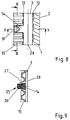
- FIGS. 8 to 10 show a further modification of the Object according to FIGS. 2 to 4 in the manner of representation there, whereby also already described again Provide parts with the numbers there and are not explained again in detail.
- the modification here is that the tab 14 with a fastening part 25 with head 26 and neck 27 is provided, which is the U-shaped cross section of the Opening 19 adapted to the end of the tab 14 and thus extends to the edge of the plate edge 15.
- the formation of the opening 19 is so far U-shaped shown and described. However, it does exist for the designs according to Figures 2 to 7 also Possibility of the cross section of the openings 19 outside the fastening parts 18 to the edge of the plate edge 15 to reduce something so that the Fasteners 18 overcoming a slight Insert the obstacle into the openings 19 and therefore not easy to get out of shown shifting mounting position.
- Figures 11 and 12 show an enlargement of the detail A of Figure 1, another training, wherein also already described parts with the introduced numbering and not again are explained.
- two neighboring, tab-shaped projections 30, 31 of the seal 3 at the end connected by a bridge 32 are located within the platemark on the Straps 30, 31 facing away from the plate.
- the one between the tabs 30 and 31 is assigned Openings 33, 34 located section 35 of the plate edge somewhat towards the bridge 32 Continuously trained, so in the area of the connection point between bridge 32 and 30, 31 the seal educational material used as little as possible becomes.
- the fact that the Cross section of the bridge 32 perpendicular to the surface of the Plate 1 is less than the cross section of the tabs 30 and 31.
- seal attachment shown in Figures 11 and 12 can also be easily pushed in make through the openings 33, 34, as a result, all of the attachment of the seal serving parts between adjacent plates. are taken, thus from external damage are protected.
Landscapes
- Engineering & Computer Science (AREA)
- Physics & Mathematics (AREA)
- Thermal Sciences (AREA)
- Mechanical Engineering (AREA)
- General Engineering & Computer Science (AREA)
- Heat-Exchange Devices With Radiators And Conduit Assemblies (AREA)
- Gasket Seals (AREA)
- Lining Or Joining Of Plastics Or The Like (AREA)
- Steam Or Hot-Water Central Heating Systems (AREA)
Description
- Figur 1
- die Draufsicht auf eine Wärmeübertragerplatte mit aufgesetzter Dichtung;
- Figur 2
- den Randbereich A in vergrößerter Darstellung;
- Figur 3
- die Schnittansicht III-III aus Figur 2;
- Figur 4
- die Schnittansicht IV-IV aus Figur 2;
- Figuren 5 bis 7 und 8 bis 10
- zwei Abwandlungen des Gegenstandes gemäß Figur 2 bis 4 in gleicher Darstellungsweise;
- Figur 11
- eine andere Ausbildung in vergrößerter Darstellung des Ausschnittes A aus Figur 1 und
- Figur 12
- die Schnittansicht XII-XII aus Figur 11.
Claims (21)
- Plattenwärmeübertrager mit unter Belassung eines Zwischenraumes fluchtend aufeinander angeordneten Wärmeübertragerplatten (1) sowie einer Umfangsdichtung zum Abschluss des Wärmeübertragerbereiches der Wärmeübertragerplatten (1), wobei eine der Platten (1) eine um den Wärmeübertragerbereich herum verlaufende Nut (10) zur Aufnahme der Dichtung (3) aufweist, an der entlang im wesentlichen gleichmäßig verteilt zahlreiche zu den Platten (1) parallele Vorsprünge (14, 20, 30, 31) mit endständigen Befestigungsteilen (18, 25, 32) ausgebildet sind, welche mit korrespondierenden Durchbrechungen (19, 21, 33, 34) des sich an die Nut anschließenden Randes (15) der einen Platte (1) in Eingriff sind,
dadurch gekennzeichnet, daß die Durchbrechungen (19, 21, 33, 34) zu einer Kante des Plattenrandes (15) hin offen ausgebildet sind. - Plattenwärmeübertrager nach Anspruch 1,
dadurch gekennzeichnet, daß die Durchbrechungen (19, 21, 33, 34) zur Außenkante des Plattenrandes (15) hin offen ausgebildet sind. - Plattenwärmeübertrager nach Anspruch 1,
dadurch gekennzeichnet, daß die Durchbrechungen zu einer Innenkante eines Plattenrandes hin offen ausgebildet sind. - Plattenwärmeübertrager nach Anspruch 1, 2 oder 3,
dadurch gekennzeichnet, daß die Vorsprünge sich im wesentlichen senkrecht zum Längsverlauf der Dichtung (3) erstreckende Laschen (14, 20, 30, 31) sind. - Plattenwärmeübertrager nach einem oder mehreren der Ansprüche 1 bis 4,
dadurch gekennzeichnet, daß der die Auflage für die Vorsprünge (4, 14, 20, 30, 31) bildende jeweilige Teil des Randes (15) der einen Platte (1) niveaugleich mit dem Grund (11) der Nut (10) ist. - Plattenwärmeübertrager nach einem oder mehreren der Ansprüche 1 bis 4,
dadurch gekennzeichnet, daß der die Auflage für die Vorsprünge (4, 14, 21, 30, 31) bildende jeweilige Teil des Randes (15) der einen Platte (1) gegenüber dem Grund (11) der Nut (10) nach oben abgetreppt ist. - Plattenwärmeübertrager nach einem oder mehreren der Ansprüche 1 bis 6,
dadurch gekennzeichnet, daß die Befestigungsteile (18, 25, 35) vom umlaufenden Außenrand bzw. Innenrand der Dichtung (3) beabstandet angeordnet sind. - Plattenwärmeübertrager nach einem oder mehreren der Ansprüche 1 bis 7,
dadurch gekennzeichnet, daß die Befestigungsteile (18, 25) senkrecht von den Vorsprüngen (4, 14, 20) in Richtung auf die eine Platte (1) ragende Teile sind. - Plattenwärmeübertrager nach einem oder mehreren der Ansprüche 1 bis 8,
dadurch gekennzeichnet, daß die Befestigungsteile im wesentlichen zylindrische oder sich zu ihren Enden hin erweiternde Zapfen sind. - Plattenwärmeübertrager nach einem oder mehreren der Ansprüche 1 bis 9,
dadurch gekennzeichnet, daß die Befestigungsteile (18, 25) unter Bildung eines Halses (16, 27) endständige, bezogen auf die Vorsprünge (14, 20) jenseits der einen Platte (1) sitzende kopfartige Erweiterungen (17, 26) aufweisen. - Plattenwärmeübertrager nach einem oder mehreren der Ansprüche 1 bis 10,
dadurch gekennzeichnet, daß die Befestigungsteile (18, 25) quer zu ihrer Längserstreckung einen kreisförmigen, elliptischen oder polygonalen Querschnitt aufweisen. - Plattenwärmeübertrager nach einem oder mehreren der Ansprüche 1 bis 11,
dadurch gekennzeichnet, daß die Befestigungsteile (25) quer zu ihrer Längserstreckung einen länglichen, im wesentlichen bis zur Außenkante des Plattenrandes (15) gehenden Querschnitt aufweisen. - Plattenwärmeübertrager nach einem oder mehreren der Ansprüche 1 bis 12,
dadurch gekennzeichnet, daß der Querschnitt der Durchbrechungen (19, 21) im wesentlichen dem des mit ihnen in Eingriff befindlichen Abschnittes (16, 27) der Befestigungsteile (18, 25) entspricht. - Plattenwärmeübertrager nach einem oder mehreren der Ansprüche 1 bis 13,
dadurch gekennzeichnet, daß der Querschnitt der Durchbrechungen bis zur Kante des flachen Randes (15) hin gleichbleibend ausgebildet ist. - Plattenwärmeübertrager nach einem oder mehreren der Ansprüche 1 bis 13,
dadurch gekennzeichnet, daß der Querschnitt der Durchbrechungen ausgehend von der Position der Befestigungsteile (18, 25) zur Kante des Plattenrandes (15) hin reduziert ist. - Plattenwärmeübertrager nach einem oder mehreren der Ansprüche 1 bis 15,
dadurch gekennzeichnet, daß die Durchbrechungen (21) im Bereich der Kante des Plattenrandes (15) eine trichterförmige Erweiterung (22) aufweisen. - Plattenwärmeübertrager nach einem oder mehreren der Ansprüche 1 bis 7,
dadurch gekennzeichnet, daß jeweils wenigstens zwei benachbarte Vorsprünge (30, 31) endständig durch ein Befestigungsteil in Form einer Brücke (32) miteinander verbunden sind, und
daß die Brücke (32) ausgehend von den den Vorsprüngen (30, 31) zugeordneten Durchbrechungen (33, 34) bezogen auf die Vorsprünge (30, 31) jenseits der einen Platte (1) angeordnet ist. - Plattenwärmeübertrager nach Anspruch 17,
dadurch gekennzeichnet, daß der von der Brücke (32) untergriffene Abschnitt (35) des Plattenrandes (15) gegenüber den benachbarten Abschnitten in Richtung von der Brücke (32) fort versetzt ist. - Plattenwärmeübertrager nach Anspruch 17 oder 18,
dadurch gekennzeichnet, daß die Brücke (32) senkrecht zur Oberfläche der einen Platte (1) eine gegenüber den Vorsprüngen (30, 31) geringere Materialstärke aufweist. - Plattenwärmeübertrager nach einem oder mehreren der Ansprüche 17 bis 19,
dadurch gekennzeichnet, daß die Durchbrechungen (33, 34) in Längsrichtung des Plattenrandes (15) gegenüber den Abmessungen der Vorsprünge (30, 31) verbreitert ausgebildet sind. - Plattenwärmetauscher nach einem oder mehreren der Ansprüche 1 bis 20,
dadurch gekennzeichnet, daß der Rand der in Richtung der Befestigungsteile (18, 25, 32) nächstfolgenden Wärmeübertragerplatte eine den Befestigungsteilen bzw. deren Enden Platze lassende Profilierung aufweist.
Applications Claiming Priority (3)
| Application Number | Priority Date | Filing Date | Title |
|---|---|---|---|
| EN19506281 | 1995-02-23 | ||
| DE19506281A DE19506281A1 (de) | 1995-02-23 | 1995-02-23 | Umfangsdichtung eines Plattenwärmeübertragers |
| DE19506281 | 1995-02-23 |
Publications (3)
| Publication Number | Publication Date |
|---|---|
| EP0729003A2 EP0729003A2 (de) | 1996-08-28 |
| EP0729003A3 EP0729003A3 (de) | 1998-10-14 |
| EP0729003B1 true EP0729003B1 (de) | 2002-04-10 |
Family
ID=7754821
Family Applications (1)
| Application Number | Title | Priority Date | Filing Date |
|---|---|---|---|
| EP95113150A Expired - Lifetime EP0729003B1 (de) | 1995-02-23 | 1995-08-22 | Plattenwärmeübertrager mit einer Umfangsdichtung |
Country Status (6)
| Country | Link |
|---|---|
| US (1) | US5727620A (de) |
| EP (1) | EP0729003B1 (de) |
| AT (1) | ATE216061T1 (de) |
| DE (2) | DE19506281A1 (de) |
| DK (1) | DK0729003T3 (de) |
| ES (1) | ES2173137T3 (de) |
Cited By (1)
| Publication number | Priority date | Publication date | Assignee | Title |
|---|---|---|---|---|
| ITVR20090014A1 (it) * | 2009-02-16 | 2010-08-17 | Luca Cipriani | Struttura di piastra per scambiatore di calore a piastre |
Families Citing this family (21)
| Publication number | Priority date | Publication date | Assignee | Title |
|---|---|---|---|---|
| IT1299659B1 (it) * | 1998-04-23 | 2000-03-24 | Cipriani Scambiatori Srl | Scambiatore di calore a piastre |
| IL125113A (en) * | 1998-06-25 | 2001-08-26 | Pessach Seidel | Heat exchanger plates and sealing gaskets therefor |
| DE10035939A1 (de) * | 2000-07-21 | 2002-02-07 | Bosch Gmbh Robert | Vorrichtung zur Wärmeübertragung |
| DE10035776C1 (de) * | 2000-07-22 | 2001-12-13 | Gea Ecoflex Gmbh | Plattenwärmetauscher |
| DE20210209U1 (de) * | 2002-06-28 | 2003-11-06 | Autokühler GmbH & Co. KG, 34369 Hofgeismar | Wärmeaustauschernetz |
| FR2910607B1 (fr) * | 2006-12-21 | 2009-02-06 | Alfa Laval Vicard Soc Par Acti | Echangeur thermique a plaques |
| SE533359C2 (sv) * | 2008-12-16 | 2010-09-07 | Alfa Laval Corp Ab | Platta och packning till en plattvärmeväxlare |
| EP2317187A1 (de) * | 2009-10-30 | 2011-05-04 | Alfa Laval Corporate AB | Dichtung und Dichtungsortungsanordnungen |
| JP5883763B2 (ja) * | 2012-10-17 | 2016-03-15 | 株式会社日阪製作所 | プレート式熱交換器 |
| DK2762823T3 (en) * | 2013-01-30 | 2017-10-09 | Alfa Laval Corp Ab | Fastener, Packing Device and Unit |
| TR201911112T4 (tr) * | 2013-12-10 | 2019-08-21 | Swep Int Ab | Geliştirilmiş akışa sahip ısı değiştirici. |
| EP2886997B1 (de) * | 2013-12-18 | 2018-04-18 | Alfa Laval Corporate AB | Wärmetauschplatte und Plattenwärmetauscher |
| DK2886998T3 (en) | 2013-12-18 | 2018-06-18 | Alfa Laval Corp Ab | Fastener, gasket device, heat exchanger plate and unit |
| DK2957851T3 (en) * | 2014-06-18 | 2017-08-07 | Alfa Laval Corp Ab | HEAT TRANSFER PLATE AND PLATE HEAT EXCHANGERS THAT INCLUDE SUCH A HEAT TRANSFER PLATE |
| CN106217918B (zh) * | 2016-09-13 | 2018-08-17 | 江苏远翔物联科技有限公司 | 拉链式封边模具 |
| US10876794B2 (en) * | 2017-06-12 | 2020-12-29 | Ingersoll-Rand Industrial U.S., Inc. | Gasketed plate and shell heat exchanger |
| US11359871B2 (en) * | 2019-07-31 | 2022-06-14 | Denso International America, Inc. | Heat exchanger with fluid flow normalization |
| RU2738541C1 (ru) * | 2019-10-31 | 2020-12-14 | Данфосс А/С | Теплообменная пластина |
| DK180498B1 (en) * | 2019-11-07 | 2021-05-27 | Danfoss As | Heat exchanger plate |
| WO2022024125A1 (en) * | 2020-07-29 | 2022-02-03 | Pessach Seidel | Heat exchanger plate and sealing gasket lockable thereto |
| CN114993077A (zh) * | 2022-04-25 | 2022-09-02 | 浙江银轮机械股份有限公司 | 换热器及其换热系统 |
Family Cites Families (15)
| Publication number | Priority date | Publication date | Assignee | Title |
|---|---|---|---|---|
| AT8436B (de) | 1900-11-15 | 1902-07-25 | Arlt & Fricke | Gasglühlichtlampe. |
| SU416550A1 (ru) * | 1972-04-25 | 1981-09-07 | Korobchanskij O A | Уплотнение дл пакета пластин |
| GB2028996B (en) * | 1978-08-30 | 1982-12-22 | Apv Co Ltd | Plate-type heat transfer apparatus |
| GB2071303B (en) * | 1980-03-10 | 1983-12-21 | Apv Co Ltd | Heat transfer apparatus |
| SE421241B (sv) * | 1980-04-30 | 1981-12-07 | Alfa Laval Ab | Plattvermevexlare |
| ATE8436T1 (de) * | 1980-04-30 | 1984-07-15 | Alfa-Laval Ab | Plattenwaermetauscher. |
| GB2075656B (en) * | 1980-05-01 | 1983-12-21 | Apv Co Ltd | Improved heat transfer apparatus |
| GB2092241B (en) * | 1981-01-30 | 1984-07-18 | Apv The Co Ltd | Gasket arrangement for plate heat exchanger |
| GB2138931B (en) * | 1983-04-18 | 1986-07-09 | Apv Int Ltd | Gasketing for heat exchanger plates |
| SE8303449L (sv) * | 1983-06-16 | 1984-12-17 | Alfa Laval Thermal | Packningsarrangemang for plattvermevexlare |
| US4905758A (en) * | 1989-07-03 | 1990-03-06 | Tranter, Inc. | Plate heat exchanger |
| SU1726965A1 (ru) * | 1990-02-05 | 1992-04-15 | Производственное Объединение "Воткинский Завод" | Пластина теплообменника |
| JP3069592B2 (ja) * | 1990-02-21 | 2000-07-24 | 株式会社日阪製作所 | プレート式熱交換器 |
| IT1239317B (it) * | 1990-04-05 | 1993-10-19 | Cipriani Scambiatori S R L | Dispositivo formante guarnizione di tenuta per piastra di scambiatore di calore dotato di piastre aventi tale dispositivo. |
| JP2992719B2 (ja) * | 1992-01-29 | 1999-12-20 | 株式会社日阪製作所 | プレート式熱交換器 |
-
1995
- 1995-02-23 DE DE19506281A patent/DE19506281A1/de not_active Withdrawn
- 1995-08-22 AT AT95113150T patent/ATE216061T1/de active
- 1995-08-22 ES ES95113150T patent/ES2173137T3/es not_active Expired - Lifetime
- 1995-08-22 EP EP95113150A patent/EP0729003B1/de not_active Expired - Lifetime
- 1995-08-22 DE DE59510156T patent/DE59510156D1/de not_active Expired - Lifetime
- 1995-08-22 DK DK95113150T patent/DK0729003T3/da active
- 1995-11-08 US US08/554,656 patent/US5727620A/en not_active Expired - Lifetime
Cited By (2)
| Publication number | Priority date | Publication date | Assignee | Title |
|---|---|---|---|---|
| ITVR20090014A1 (it) * | 2009-02-16 | 2010-08-17 | Luca Cipriani | Struttura di piastra per scambiatore di calore a piastre |
| WO2010092556A1 (en) * | 2009-02-16 | 2010-08-19 | Luca Cipriani | A plate structure and gasket for a plate heat exchanger and respective plate heat exchanger |
Also Published As
| Publication number | Publication date |
|---|---|
| DE59510156D1 (de) | 2002-05-16 |
| EP0729003A3 (de) | 1998-10-14 |
| ES2173137T3 (es) | 2002-10-16 |
| DE19506281A1 (de) | 1996-08-29 |
| ATE216061T1 (de) | 2002-04-15 |
| EP0729003A2 (de) | 1996-08-28 |
| US5727620A (en) | 1998-03-17 |
| DK0729003T3 (da) | 2002-06-17 |
Similar Documents
| Publication | Publication Date | Title |
|---|---|---|
| EP0729003A2 (de) | Umfangsdichtung eines Plattenwärme-übertragers | |
| EP0298225A1 (de) | Etagenturm zur Warenausstellung | |
| DE2221312A1 (de) | Vorgefertigte flanschverbindungsvorrichtung | |
| EP0399955B1 (de) | Verschlusselement zur Sicherung eines Deckels an einem Rahmen | |
| DE202013011960U1 (de) | Steckverbinder zum Verbinden von Hohlprofilen | |
| EP1088577A1 (de) | Kolonnentrennwand | |
| EP0277330A1 (de) | Montageknoteneinheit | |
| DE19539157C2 (de) | Verbindung eines Leiterprofils mit einem eingesteckten Innenteil | |
| DE19712278B4 (de) | Bodenelement | |
| EP0345222A2 (de) | Gitterrost und Tragrahmen dazu | |
| EP3865623B1 (de) | Fugenprofil | |
| EP0687790B1 (de) | Linearverbinder für hohle Abstandsprofile eines Mehrscheibenisolierglases | |
| WO1993018336A1 (de) | Grundgestell für maschinen und dergleichen | |
| DE202004013686U1 (de) | Gerader Steckverbinder | |
| AT526547A1 (de) | Tragstab und Abdeckelement zur Bildung eines Gitterrostes | |
| DE8617287U1 (de) | Verglasungsklotz | |
| CH625010A5 (en) | Self-supporting, vertical partition wall and a method of producing the same | |
| DE2446328C2 (de) | Abschirmvorrichtung für Wandöffnungen | |
| EP0877125A2 (de) | Rahmen für die Montage von Sanitärartikeln | |
| DE4403159C2 (de) | Entwässerungsrinne | |
| CH690453A5 (de) | Objektsicherungsgitter. | |
| DE2459625C3 (de) | Vorrichtung zur Herstellung von rohr- oder säulenförmigen Erzeugnissen aus Beton | |
| DE4306561C2 (de) | Kreuzstrom-Wärmetauscher | |
| DE8708104U1 (de) | Durchführungselement zur Durchführung eines Rohres durch ein Gehäuse | |
| DE20315711U1 (de) | Sammelschienenträger |
Legal Events
| Date | Code | Title | Description |
|---|---|---|---|
| PUAI | Public reference made under article 153(3) epc to a published international application that has entered the european phase |
Free format text: ORIGINAL CODE: 0009012 |
|
| AK | Designated contracting states |
Kind code of ref document: A2 Designated state(s): AT CH DE DK ES FR GB IE IT LI NL SE |
|
| RAP1 | Party data changed (applicant data changed or rights of an application transferred) |
Owner name: API SCHMIDT-BRETTEN GMBH & CO. KG |
|
| PUAL | Search report despatched |
Free format text: ORIGINAL CODE: 0009013 |
|
| AK | Designated contracting states |
Kind code of ref document: A3 Designated state(s): AT CH DE DK ES FR GB IE IT LI NL SE |
|
| 17P | Request for examination filed |
Effective date: 19990212 |
|
| 17Q | First examination report despatched |
Effective date: 20001113 |
|
| GRAG | Despatch of communication of intention to grant |
Free format text: ORIGINAL CODE: EPIDOS AGRA |
|
| GRAG | Despatch of communication of intention to grant |
Free format text: ORIGINAL CODE: EPIDOS AGRA |
|
| GRAH | Despatch of communication of intention to grant a patent |
Free format text: ORIGINAL CODE: EPIDOS IGRA |
|
| RTI1 | Title (correction) |
Free format text: PLATE HEATEXCHANGER WITH AN EDGE SEAL |
|
| GRAH | Despatch of communication of intention to grant a patent |
Free format text: ORIGINAL CODE: EPIDOS IGRA |
|
| REG | Reference to a national code |
Ref country code: GB Ref legal event code: IF02 |
|
| GRAA | (expected) grant |
Free format text: ORIGINAL CODE: 0009210 |
|
| AK | Designated contracting states |
Kind code of ref document: B1 Designated state(s): AT CH DE DK ES FR GB IE IT LI NL SE |
|
| REF | Corresponds to: |
Ref document number: 216061 Country of ref document: AT Date of ref document: 20020415 Kind code of ref document: T |
|
| REG | Reference to a national code |
Ref country code: CH Ref legal event code: EP |
|
| REG | Reference to a national code |
Ref country code: GB Ref legal event code: FG4L Free format text: GERMAN |
|
| REG | Reference to a national code |
Ref country code: IE Ref legal event code: FG4D Free format text: GERMAN |
|
| REF | Corresponds to: |
Ref document number: 59510156 Country of ref document: DE Date of ref document: 20020516 |
|
| REG | Reference to a national code |
Ref country code: CH Ref legal event code: NV Representative=s name: R. A. EGLI & CO. PATENTANWAELTE |
|
| REG | Reference to a national code |
Ref country code: DK Ref legal event code: T3 |
|
| GBT | Gb: translation of ep patent filed (gb section 77(6)(a)/1977) |
Effective date: 20020710 |
|
| ET | Fr: translation filed | ||
| REG | Reference to a national code |
Ref country code: ES Ref legal event code: FG2A Ref document number: 2173137 Country of ref document: ES Kind code of ref document: T3 |
|
| PLBE | No opposition filed within time limit |
Free format text: ORIGINAL CODE: 0009261 |
|
| STAA | Information on the status of an ep patent application or granted ep patent |
Free format text: STATUS: NO OPPOSITION FILED WITHIN TIME LIMIT |
|
| 26N | No opposition filed |
Effective date: 20030113 |
|
| PGFP | Annual fee paid to national office [announced via postgrant information from national office to epo] |
Ref country code: IE Payment date: 20130819 Year of fee payment: 19 |
|
| PGFP | Annual fee paid to national office [announced via postgrant information from national office to epo] |
Ref country code: NL Payment date: 20140821 Year of fee payment: 20 Ref country code: DK Payment date: 20140825 Year of fee payment: 20 Ref country code: CH Payment date: 20140821 Year of fee payment: 20 Ref country code: DE Payment date: 20140818 Year of fee payment: 20 |
|
| PGFP | Annual fee paid to national office [announced via postgrant information from national office to epo] |
Ref country code: SE Payment date: 20140821 Year of fee payment: 20 Ref country code: AT Payment date: 20140820 Year of fee payment: 20 Ref country code: ES Payment date: 20140827 Year of fee payment: 20 Ref country code: GB Payment date: 20140821 Year of fee payment: 20 Ref country code: FR Payment date: 20140819 Year of fee payment: 20 |
|
| PGFP | Annual fee paid to national office [announced via postgrant information from national office to epo] |
Ref country code: IT Payment date: 20140827 Year of fee payment: 20 |
|
| REG | Reference to a national code |
Ref country code: IE Ref legal event code: MM4A |
|
| REG | Reference to a national code |
Ref country code: DE Ref legal event code: R071 Ref document number: 59510156 Country of ref document: DE |
|
| REG | Reference to a national code |
Ref country code: DK Ref legal event code: EUP Effective date: 20150822 |
|
| REG | Reference to a national code |
Ref country code: CH Ref legal event code: PL |
|
| PG25 | Lapsed in a contracting state [announced via postgrant information from national office to epo] |
Ref country code: IE Free format text: LAPSE BECAUSE OF NON-PAYMENT OF DUE FEES Effective date: 20140822 |
|
| REG | Reference to a national code |
Ref country code: NL Ref legal event code: V4 Effective date: 20150822 |
|
| REG | Reference to a national code |
Ref country code: GB Ref legal event code: PE20 Expiry date: 20150821 |
|
| REG | Reference to a national code |
Ref country code: SE Ref legal event code: EUG |
|
| REG | Reference to a national code |
Ref country code: AT Ref legal event code: MK07 Ref document number: 216061 Country of ref document: AT Kind code of ref document: T Effective date: 20150822 |
|
| PG25 | Lapsed in a contracting state [announced via postgrant information from national office to epo] |
Ref country code: GB Free format text: LAPSE BECAUSE OF EXPIRATION OF PROTECTION Effective date: 20150821 |
|
| REG | Reference to a national code |
Ref country code: ES Ref legal event code: FD2A Effective date: 20151127 |
|
| PG25 | Lapsed in a contracting state [announced via postgrant information from national office to epo] |
Ref country code: ES Free format text: LAPSE BECAUSE OF EXPIRATION OF PROTECTION Effective date: 20150823 |