EP0724686B1 - Control of fuelling rate of an engine - Google Patents
Control of fuelling rate of an engine Download PDFInfo
- Publication number
- EP0724686B1 EP0724686B1 EP94930864A EP94930864A EP0724686B1 EP 0724686 B1 EP0724686 B1 EP 0724686B1 EP 94930864 A EP94930864 A EP 94930864A EP 94930864 A EP94930864 A EP 94930864A EP 0724686 B1 EP0724686 B1 EP 0724686B1
- Authority
- EP
- European Patent Office
- Prior art keywords
- engine
- change
- fuel
- per cycle
- filter constant
- Prior art date
- Legal status (The legal status is an assumption and is not a legal conclusion. Google has not performed a legal analysis and makes no representation as to the accuracy of the status listed.)
- Expired - Lifetime
Links
- 239000000446 fuel Substances 0.000 claims description 103
- 230000008859 change Effects 0.000 claims description 85
- 238000000034 method Methods 0.000 claims description 37
- 230000001419 dependent effect Effects 0.000 claims description 15
- 230000004044 response Effects 0.000 claims description 12
- 230000009471 action Effects 0.000 claims description 4
- 230000003044 adaptive effect Effects 0.000 claims description 4
- 230000003247 decreasing effect Effects 0.000 claims description 3
- 238000001914 filtration Methods 0.000 description 30
- 230000000694 effects Effects 0.000 description 8
- 238000007726 management method Methods 0.000 description 8
- 238000013016 damping Methods 0.000 description 6
- 238000002347 injection Methods 0.000 description 6
- 239000007924 injection Substances 0.000 description 6
- 230000001133 acceleration Effects 0.000 description 5
- 230000007423 decrease Effects 0.000 description 5
- 238000010586 diagram Methods 0.000 description 5
- 238000002485 combustion reaction Methods 0.000 description 4
- 238000006243 chemical reaction Methods 0.000 description 3
- 230000009467 reduction Effects 0.000 description 3
- 230000035939 shock Effects 0.000 description 3
- 230000001052 transient effect Effects 0.000 description 2
- 230000002411 adverse Effects 0.000 description 1
- 230000032683 aging Effects 0.000 description 1
- 230000000712 assembly Effects 0.000 description 1
- 238000000429 assembly Methods 0.000 description 1
- 230000008901 benefit Effects 0.000 description 1
- 230000005540 biological transmission Effects 0.000 description 1
- 230000001010 compromised effect Effects 0.000 description 1
- 230000000994 depressogenic effect Effects 0.000 description 1
- 230000006866 deterioration Effects 0.000 description 1
- 230000001627 detrimental effect Effects 0.000 description 1
- 238000009499 grossing Methods 0.000 description 1
- 238000009434 installation Methods 0.000 description 1
- 238000002955 isolation Methods 0.000 description 1
- 238000012886 linear function Methods 0.000 description 1
- 230000035882 stress Effects 0.000 description 1
- 230000007704 transition Effects 0.000 description 1
Images



Classifications
-
- F—MECHANICAL ENGINEERING; LIGHTING; HEATING; WEAPONS; BLASTING
- F02—COMBUSTION ENGINES; HOT-GAS OR COMBUSTION-PRODUCT ENGINE PLANTS
- F02D—CONTROLLING COMBUSTION ENGINES
- F02D41/00—Electrical control of supply of combustible mixture or its constituents
- F02D41/02—Circuit arrangements for generating control signals
- F02D41/14—Introducing closed-loop corrections
- F02D41/1497—With detection of the mechanical response of the engine
-
- F—MECHANICAL ENGINEERING; LIGHTING; HEATING; WEAPONS; BLASTING
- F02—COMBUSTION ENGINES; HOT-GAS OR COMBUSTION-PRODUCT ENGINE PLANTS
- F02D—CONTROLLING COMBUSTION ENGINES
- F02D41/00—Electrical control of supply of combustible mixture or its constituents
- F02D41/02—Circuit arrangements for generating control signals
- F02D41/04—Introducing corrections for particular operating conditions
- F02D41/045—Detection of accelerating or decelerating state
-
- F—MECHANICAL ENGINEERING; LIGHTING; HEATING; WEAPONS; BLASTING
- F02—COMBUSTION ENGINES; HOT-GAS OR COMBUSTION-PRODUCT ENGINE PLANTS
- F02D—CONTROLLING COMBUSTION ENGINES
- F02D43/00—Conjoint electrical control of two or more functions, e.g. ignition, fuel-air mixture, recirculation, supercharging or exhaust-gas treatment
-
- F—MECHANICAL ENGINEERING; LIGHTING; HEATING; WEAPONS; BLASTING
- F02—COMBUSTION ENGINES; HOT-GAS OR COMBUSTION-PRODUCT ENGINE PLANTS
- F02D—CONTROLLING COMBUSTION ENGINES
- F02D11/00—Arrangements for, or adaptations to, non-automatic engine control initiation means, e.g. operator initiated
- F02D11/06—Arrangements for, or adaptations to, non-automatic engine control initiation means, e.g. operator initiated characterised by non-mechanical control linkages, e.g. fluid control linkages or by control linkages with power drive or assistance
- F02D11/10—Arrangements for, or adaptations to, non-automatic engine control initiation means, e.g. operator initiated characterised by non-mechanical control linkages, e.g. fluid control linkages or by control linkages with power drive or assistance of the electric type
- F02D11/105—Arrangements for, or adaptations to, non-automatic engine control initiation means, e.g. operator initiated characterised by non-mechanical control linkages, e.g. fluid control linkages or by control linkages with power drive or assistance of the electric type characterised by the function converting demand to actuation, e.g. a map indicating relations between an accelerator pedal position and throttle valve opening or target engine torque
-
- F—MECHANICAL ENGINEERING; LIGHTING; HEATING; WEAPONS; BLASTING
- F02—COMBUSTION ENGINES; HOT-GAS OR COMBUSTION-PRODUCT ENGINE PLANTS
- F02D—CONTROLLING COMBUSTION ENGINES
- F02D41/00—Electrical control of supply of combustible mixture or its constituents
- F02D41/02—Circuit arrangements for generating control signals
- F02D41/14—Introducing closed-loop corrections
- F02D41/1401—Introducing closed-loop corrections characterised by the control or regulation method
- F02D2041/1413—Controller structures or design
- F02D2041/1432—Controller structures or design the system including a filter, e.g. a low pass or high pass filter
-
- F—MECHANICAL ENGINEERING; LIGHTING; HEATING; WEAPONS; BLASTING
- F02—COMBUSTION ENGINES; HOT-GAS OR COMBUSTION-PRODUCT ENGINE PLANTS
- F02D—CONTROLLING COMBUSTION ENGINES
- F02D41/00—Electrical control of supply of combustible mixture or its constituents
- F02D41/30—Controlling fuel injection
- F02D41/38—Controlling fuel injection of the high pressure type
- F02D2041/389—Controlling fuel injection of the high pressure type for injecting directly into the cylinder
-
- F—MECHANICAL ENGINEERING; LIGHTING; HEATING; WEAPONS; BLASTING
- F02—COMBUSTION ENGINES; HOT-GAS OR COMBUSTION-PRODUCT ENGINE PLANTS
- F02D—CONTROLLING COMBUSTION ENGINES
- F02D2200/00—Input parameters for engine control
- F02D2200/02—Input parameters for engine control the parameters being related to the engine
- F02D2200/10—Parameters related to the engine output, e.g. engine torque or engine speed
- F02D2200/1012—Engine speed gradient
-
- F—MECHANICAL ENGINEERING; LIGHTING; HEATING; WEAPONS; BLASTING
- F02—COMBUSTION ENGINES; HOT-GAS OR COMBUSTION-PRODUCT ENGINE PLANTS
- F02D—CONTROLLING COMBUSTION ENGINES
- F02D2400/00—Control systems adapted for specific engine types; Special features of engine control systems not otherwise provided for; Power supply, connectors or cabling for engine control systems
- F02D2400/04—Two-stroke combustion engines with electronic control
-
- F—MECHANICAL ENGINEERING; LIGHTING; HEATING; WEAPONS; BLASTING
- F02—COMBUSTION ENGINES; HOT-GAS OR COMBUSTION-PRODUCT ENGINE PLANTS
- F02D—CONTROLLING COMBUSTION ENGINES
- F02D41/00—Electrical control of supply of combustible mixture or its constituents
- F02D41/30—Controlling fuel injection
- F02D41/3011—Controlling fuel injection according to or using specific or several modes of combustion
- F02D41/3017—Controlling fuel injection according to or using specific or several modes of combustion characterised by the mode(s) being used
- F02D41/3023—Controlling fuel injection according to or using specific or several modes of combustion characterised by the mode(s) being used a mode being the stratified charge spark-ignited mode
Definitions
- This invention relates to the control of the amount of fuel delivered to a fuel injected internal combustion engine, and in particular, an internal combustion engine that is subject to a sudden variation in torque demand, such as may occur during driving conditions in an automobile or other vehicle.
- a fuel injection control apparatus is known from EP 0433671 for controlling the fuel injection quantity delivered to an air led engine which corrects a reference fuel injection quantity that is set based on the quantity of intake air sucked into the engine by using a transient correction value set in relation to the transient condition of the engine.
- the system compensates for the deviation in the air/fuel ratio that is commonly experienced due to variations in atmosphere air pressure, for example at high altitude there is a decrease in air density, so that the reference fuel injection quantity that is required at low altitude is excessive at such high altitudes.
- Occasions may occur during the driving or operation of a vehicle, where the engine speed is caused to rapidly increase or decrease. This may be due to the driver demand or may result from the engine's control system as may occur, for example, during automatic gear changing.
- the acceleration or deceleration may have the effect of increasing or decreasing the fuel requirement of the engine in a manner which may contribute to under-fuelling or over-fuelling of the engine during several engine cycles. This under-fuelling or over-fuelling may lead to less than optimum engine performance.
- the acceleration or deceleration especially if sudden, may cause a large movement of the engine relative to the vehicle chassis due to the torque reaction thereof which is typically followed by an impact at the engine mount(s) when the full compliance of the mount(s) is taken up.
- Such large movement and impact at the engine mount(s) is undesirable from the point of view of driver and/or passenger comfort and places stresses on the engine mount(s) that are better avoided. This phenomenon is commonly referred to as "tip-in” or "tip-out”.
- FPC Demand required per cycle
- dFPC/dt rate of change of the fuel required per cycle with time
- EPC Demand the rate of change of the fuel required per cycle with time
- FPC/dt the rate of change of the fuel required per cycle with time
- tip-in/tip-out will generally be more pronounced in engines which are able to provide a quick response to changes in driver demand.
- the applicant's stratified-charge, air-assisted, direct fuel injected two-stroke engines are particularly responsive to rapid changes in load demand, such as may be required by the driver.
- These engines differ from conventional homogeneous charge engines in that the driver demand controls the engine's fuelling rate rather than the airflow to the engine as would normally be the case.
- the inherent inertia and other lags associated with air-flow controlled engines essentially do not have the same effect on the applicant's engine. Accordingly, it may be desirable, in some instances, to apply a damping function to this response while under other situations allowing the driver the full benefit of the brisk response of the engine.
- the present invention is aimed at providing a method of controlling fuel delivery to an engine during the above-described conditions wherein the above problems are overcome or substantially reduced.
- the present invention provides a method of controlling the mass of fuel delivered to a fuel led engine subject to a change in engine load demand comprising the steps of determining a value of the fuel
- the method may be implemented in a fuel based control system in which the operator does not directly control the fuelling to the engine but merely generates a signal ("demand" signal) which indicates the operator's requirements (e.g. increase or decrease in power output from the engine).
- This demand signal may then be processed by an Electronic Control Unit (ECU) which determines the fuel and air flow requirements of the engine.
- ECU Electronic Control Unit
- the operator "demand" signal conveniently determined as a function of accelerator pedal position, is input to the ECU which outputs the required fuel per cycle demand of the engine and controls fuel delivery accordingly.
- the rate of change of fuel per cycle with time may be measured in accordance with the invention and then filtered, that is, multiplied by a filter constant to reduce the rate of change of fuel per cycle with time to no greater than a predetermined threshold level that causes a degree of engine movement that is uncomfortable to a typical driver or operator of the engine and/or is adverse to the life of the engine mounts.
- the threshold level may be time variant and may be determined statistically or may take account of mechanical features such as the life or durability of the engine mounts or otherwise.
- the ECU may be configured to change the engine load demand independently of driver action, such as is desirable during gear ratio changes in an automatic transmission gearbox.
- the invention is also applicable to non-driver initiated load demand changes.
- the filter or damping constant required will be stored within a look-up table provided with preset values for particular rates of change of fuel per cycle with time under particular engine speed and load conditions.
- the ECU provides the appropriate filter constant in accordance with engine operating conditions.
- the look-up table which stores the filter or damping constants or intermediate look-up tables which may be required to generate inputs for this filter constant look-up table may advantageously be made dependent on the sensed road speed of the vehicle.
- the sensed road speed of the vehicle is itself dependent on, and may be calculated, if required, together with other engine operating parameters, from engine speed and load.
- the look-up table which stores the required filter or damping constant may be arranged to be adaptive with respect to time. Accordingly, if a particular selected filter constant results in, for example, an unsatisfactory engine operating condition, each of several times that the filter constant is applied to a required fuel per cycle demand of the engine, the filter constant may be incremented upwardly or downwardly as is appropriate and substituted for the filter constant value previously stored within the look-up table.
- the determined rate of change of fuel required per cycle with time may be constant (a linear function of fuelling with time) or may be time variant .
- the ECU may calculate a function representative of the variation in the rate of change of fuel per cycle with time for the engine.
- the filtering or damping of the rate of change of fuelling rate of the engine as demanded by the driver or ECU is instantaneous.
- This is particularly advantageous in a fuel based control system where, as previously mentioned, there is typically less inertia and lag than in a typical air based homogeneous charge control system.
- a fast filtering or damping response is necessary in a fuel based control system to obtain the desired effect of smoothing changes in the rate of fuelling and/or varying a value of the rate of change of fuel delivered per cycle of the engine to no greater than a predetermined threshold level.
- the degree of filtering may be time variant to take account of features such as the behaviour of the engine mounts. It is apparent that the movement of the engine will be most severe at onset of tip-in/tip-out where the engine mounts are typically at their most compliant. As the movement of the engine becomes more pronounced the compliance of the mounts generally decreases. Thus the degree of filtering may be varied to take account of this and the filter constant can be initially calculated to ensure a smaller rate of change of fuelling for the engine when the mounts are at their most compliant.
- recalculation of the filter constant can occur to increase the rate of change of fuelling and enable a more rapid approach to the demand fuel per cycle with time because the increasing stiffness or decreasing compliance of the engine mounts will tend to offset the likelihood of occurrence of undesirable levels of tip-in/tip-out behaviour.
- Such recalculation of the filter constant may occur stepwise or more gradually.
- the invention provides a fuel control system for a fuel led engine subject to a change in engine load demand comprising a control unit provided with means for determining a change in engine load demand, means for determining a value of the fuel required per cycle (FPC Demand ) in accordance with the change in load demand, means for determining the rate of change of the fuel required per cycle with time (dFPC/dt) based on the determined value of the fuel required per cycle (FPC Demand ), means for determining a filter constant dependent upon the determined rate of change of fuel required per cycle with time, and means for applying said filter constant to the determined value of the fuel required per cycle (FPC Demand ) to maintain the rate of change of fuel per cycle delivered to the engine with time at no greater than a predetermined threshold value.
- a control unit provided with means for determining a change in engine load demand, means for determining a value of the fuel required per cycle (FPC Demand ) in accordance with the change in load demand, means for determining the rate of change of the fuel required per cycle with time (d
- the means to determine the filter constant may provide an appropriate filter constant in accordance with sensed engine operating conditions.
- the filter constant may be determined in response to sensed engine speed, sensed engine load, the sensed road speed of a vehicle within which the engine is mounted and/or a sensed change in gear of the vehicle.
- the filter constant is a function of parameters which may affect the operation of the engine and hence the "drivability" of the vehicle within which the engine is mounted and thereby provide better compensation for any tip-in/tip-out behaviour of the engine.
- the filter constant may be made dependent upon other sensed engine operating parameters.
- air intake flow and fuel flow sensors may also be incorporated within the system for example, as part of the means for determining the filter constant.
- the means for determining the filter constant forms part of a, generally electronic, control unit which constitutes a key component of the system. Appropriately programmed control units and desired sensors may be supplied or arranged for installation in vehicle or on the engine.
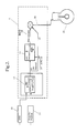
- FIG. 1 of the drawings there is depicted diagrammatically the method of operation of an engine management system to control fuelling to a vehicle engine in accordance with the method above discussed.
- the portion of the diagram within the dotted outline consists of part of an electronic control unit (ECU) 9 forming a key component of an engine management system, ECU controlled engine management systems per se being known in the art.
- the ECU 9 receives signals indicating the engine speed from the engine speed sensor 10 and engine load demand from the load demand sensor 11, the latter typically being indicated by the position of a potentiometer attached to the driver operated throttle pedal. Both input signals are advantageously filtered to remove noise and avoid hunting.
- the ECU 9 may be arranged to alter the engine load demand independently of the driver operated throttle pedal and hence the load demand sensor 11 may be configured to equally sense such non-driver initiated signals.
- the ECU 9 is capable of determining the rate of change of engine speed with respect to time and the rate of change of engine load demand with respect to time from the aforementioned signals. Also, as previously mentioned, the ECU 9 may be adapted to receive signals indicating the vehicle road speed from an appropriate road speed sensor, if desired, or may in fact generate such signals from other sensed or inputted engine operating parameters. Alternatively, or additionally, a signal indicating the gear in which the engine is engaged may be input to the ECU 9. The "gear signal" may indicate whether enablement of the filtering routine is actually required. As with the vehicle road speed, the gear signal may be calculated as a function of engine operating parameters, such as for example, road speed and engine speed. Then, for example and by analogy, at low gear and low engine speed conditions, filtering of the rate of change of fuelling (ie: dFPC / dt ) is more likely to be required.
- road speed as an input variable to the ECU 9 or a variable generated by the ECU 9 such that the method of operation of the engine management system is less compromised. That is, depending upon vehicle road speed, filtering of the rate of change of fuelling of the engine may be too aggressive or insufficient due to the fact that, depending upon what gear the vehicle is in, it is possible to have the same fuelling rate for a number of different vehicle speeds. For example, at low road speed and low engine speed, a sudden increase in the engine load demand followed by a sudden decrease in the engine load demand would typically result in undesirable tip-in/tip-out behaviour.
- Such a situation may typically correspond, for example, to a brief acceleration in low gear such as may be likely when manoeuvring in a car parking area. Accordingly, this situation is one in which it is highly desirable to adopt heavy filtering of the rate of change of fuelling to avoid tip in/tip out.
- the filtering routine may be made dependent upon a signal from a clutch switch such that no, or a reduced level of filtering can take place during a driver gear change event.
- the ECU would treat any other reduction as a possible tip-in or tip-out situation and apply the filtering accordingly. It should be noted that similar compensation would be equally applicable no matter whether a clutch signal is received whilst commencing or completing a gear change event.
- a fuel per cycle or FPC demand look-up table or map 12 produces a signal indicating the demand fuelling rate per cycle (FPC demand) 13 of the engine 20.
- FPC demand the demand fuelling rate per cycle
- the ECU 9 is also able to calculate the rate of change in fuel demand per cycle of the engine with time ( dFPC / dt ) 14. Conveniently, this value is determined by taking two FPC demand readings over a predetermined time interval where the time interval is the time between the recordal of the two FPC demand values. Conveniently, the two FPC demand values mentioned will be the demand FPC as determined as a function of a new pedal position and the preceding demand FPC.
- the signal 13 indicating the demand fuelling rate (FPC demand) of the engine 20 is input to a second look-up table or map 15 together with a road speed signal 16 from which a base filter constant (B) 17 is calculated.
- the road speed signal 16 is calculated by the ECU 9 from sensed or known engine operating parameters.
- the base filter constant 17 and the actual rate of change of fuelling rate ( dFPC / dt )14 are then input to a third look-up table or map 18 which provides, if necessary, a true filter constant value 19.
- This true filter constant 19 is then applied to the original demand FPC value 13 such that a filtered or damped FPC value 30 is generated and can be input as an operation control parameter for the engine 20.
- This "true" filter constant value 19 is appropriate for the particular value of dFPC / dt , such that the rate of change of fuelling to the new value for demand FPC is reduced to a desired level (i.e: a level which is below a predetermined threshold level of dFPC/ dt and which avoids undesirable tip-in/tip-out behaviour).
- This controlled rate of change of the demand FPC will not result in misfuelling of the engine 20, yet provides satisfactory fuelling for an acceptable level of acceleration or deceleration as the case may require.
- the map 18 which calculates the true filter constants is provided with predetermined filter constants found satisfactory for the particular dFPC/dt demanded by the driver or operator or the ECU 9. This improves the driveability of the vehicle as the movement of the engine 20 and any resultant impact at the engine mount(s) is controlled to an acceptable or more desirable level.
- the filtering of the demand FPC signal 13 is instantaneous and continues until the acceleration or deceleration is complete.
- Such a system is shown in Figure 2. Its operation may be briefly described as being in accordance with that described with reference to Figure 1, without a correction for road speed.
- the second map 15 is not required.
- a base filter constant 24 is produced by a look-up table or map 23 as a function of the rate of change of fuelling (dFPC/ dt ) 14 and fuel demand 13 alone.
- the base filter constant 24 is then applied to the original fuel demand or demand FPC 13 such that the filtered or damped FPC value 30 is generated and can be input as an operation control parameter for the engine 20.
- the fuel per cycle 13 and actual air per cycle 21 signals are also provided as inputs to an air/fuel ratio comparator 25, wherein the actual air/fuel ratio based on these inputs is compared with a censored air/fuel ratio which is preset on the basis of engine load demand or pedal position and engine speed.
- the censored air/fuel ratios are stored in a map and will normally be a range between maximum or minimum predetermined limits. The demanded air/fuel ratio is not to exceed the censored air/fuel ratio limits, so that, for example, the rich misfire limit of the engine is not exceeded.
- a correction module 26 is enabled such that correction will be made to the fuel per cycle delivered to the engine 20, so that the air/fuel ratio will be within the permissible variation from the censored air/fuel ratio.
- the rate of change of the censored fuel demand per cycle (dFPC/dt censored ) can be input to the base filter constant map 15 which provides a base filter constant 17 appropriate for the particular value of dFPC/dt censored such that the rate of change of fuelling dFPC/dt 14 is reduced to a manageable level as discussed above with reference to Figure 1.
- the system may also be configured such that, if the rate of change of fuel per cycle dFPC/dt 14 exceeds a certain threshold value even at high road speed, the filtering routine can still be enabled.
- the object of the filtering routine is improved driver comfort and the system is to be configured to achieve that end.
- the values of the filter constants may be adaptive with time such that if, for instance, a selected filter constant 19, 24 results in rich misfire of the engine 20, as sensed, for example, by a combustion chamber pressure transducer, each of several times that the filter constant 19, 24 is applied to a specific FPC demand value 13, the filter constant 19, 24 may be incremented downwardly as required and substituted for the filter constant value previously held in the filter constant map 18, 23. In this way, the desired filtering and thus fuelling condition of the engine 20 is maintained.
- the filter constants 19, 24 or the filter constant map 18, 23 may be made adaptive to allow for changes or differences in the engine mounts.
- the ECU 9 can be programmed to take account of such factors.
- the ECU 9 could be configured such that it is capable of adapting the filter constant map 18, 23 in respect of different engine mounts such as would be the case if the vehicle engine mounts were replaced.
- the ECU 9 may receive or generate signals from suitably located accelerometers or sensed crankshaft fluctuations.
- the ECU 9 will be the ECU 9 that will rapidly reduce the load demand and then re-apply the load demand so that there is a smooth transition during gear changes. Therefore, the method may be applied to control the rate of fuelling during return of the engine to a higher load demand whereas no filtering may be necessary to the reduction in fuelling of the engine 20 on the gear change.
- the filter constant is made a function of time, with the degree of filtering being varied to take into account the variable behaviour of the engine mounts in response to engine movement caused by a change in engine load demand.
- Engine mounts are typically initially compliant to impacts or shocks exerted thereon and then become stiffer or less compliant as the mounts take up the force applied thereto by the engine. Therefore the degree of filtering of the rate of change of fuel per cycle with time can be varied to take this phenomenon into account. This is accomplished in the following manner.
- a first heavy level of filtering or reduction of the rate of change of fuelling is required to restrain or control the initial responsive movement of the engine onto its mounts; the mounts in question being the mounts that will receive the resultant force caused by the movement of the engine, whether in response to tip-in or tip-out.
- the engine is prevented from gaining sufficient momentum that would cause a resultant shock being transmitted to the vehicle via the engine mounts.
- the mounts commence to take up the resultant force generated by the movement of the engine - in other words, the mounts begin becoming less compliant - a greater rate of change of fuelling to the engine can be tolerated as, the initial and, typically, more substantial movement of the engine has been controlled. It follows that, after the first "compliant" phase is complete, the engine mounts have taken up a substantial proportion of the resultant force generated by this engine movement.
- the filter constant can be recalculated and the degree of filtering may be reduced without the consequential increase in the rate of change of fuelling producing a significant impact or shock at the engine mounts because the stiffness of the mounts has increased to a level wherein the degree of movement of the engine does not impinge on driver comfort.
- the variation in filtering achieved by recalculation of the filter constant may be stepwise or may be gradual, possibly being a function of the degree of engine movement that has occurred as determined with reference to time or monitored engine mount stiffness. Such variation in filtering can lead to better response as the filtered rate of change of fuelling can be made to more closely match that demanded by the driver or may enable achievement of the final demanded FPC at substantially the same rate or the time that the final demand FPC would have been achieved if the demanded rate of change of fuelling had been delivered without filtering.
- an injection event or perhaps a time counter may be employed which is enabled when, for example, the operator demand increases suddenly, that is, from idle to wide open throttle at low engine speed which would typically result in an unacceptable level of tip-in.
- the ECU 9 may then provide a filter constant that causes a lower rate of change of fuelling to be obtained during the early injection events following counter enablement.
- the filter constant may be calculated in response to engine speed, gear anc road speed or other parameters as above described such that the initial rate of change of fuelling of the engine remains below the threshold level that would cause excessive engine movement.
- the fuelling rate can be increased with reduced prospect of excessive engine movement and, consequently, the filter constant value may be varied so that the rate of change of fuelling enables a quicker approach to the final demand value as the counter increments steadily upwards.
- the counter may be set to zero and disabled until the next tip-in/tip-out event.
Landscapes
- Engineering & Computer Science (AREA)
- Chemical & Material Sciences (AREA)
- Combustion & Propulsion (AREA)
- Mechanical Engineering (AREA)
- General Engineering & Computer Science (AREA)
- Electrical Control Of Air Or Fuel Supplied To Internal-Combustion Engine (AREA)
- Combined Controls Of Internal Combustion Engines (AREA)
- Control Of Vehicle Engines Or Engines For Specific Uses (AREA)
Applications Claiming Priority (4)
| Application Number | Priority Date | Filing Date | Title |
|---|---|---|---|
| AUPM194993 | 1993-10-21 | ||
| AUPM1949/93 | 1993-10-21 | ||
| AUPM194993 | 1993-10-21 | ||
| PCT/AU1994/000639 WO1995011377A1 (en) | 1993-10-21 | 1994-10-20 | Control of fuelling rate of an engine |
Publications (3)
| Publication Number | Publication Date |
|---|---|
| EP0724686A1 EP0724686A1 (en) | 1996-08-07 |
| EP0724686A4 EP0724686A4 (en) | 1998-05-06 |
| EP0724686B1 true EP0724686B1 (en) | 2001-04-04 |
Family
ID=3777289
Family Applications (1)
| Application Number | Title | Priority Date | Filing Date |
|---|---|---|---|
| EP94930864A Expired - Lifetime EP0724686B1 (en) | 1993-10-21 | 1994-10-20 | Control of fuelling rate of an engine |
Country Status (10)
| Country | Link |
|---|---|
| EP (1) | EP0724686B1 (es) |
| JP (1) | JP3727340B2 (es) |
| KR (1) | KR100351580B1 (es) |
| CN (1) | CN1055521C (es) |
| BR (1) | BR9407872A (es) |
| CA (1) | CA2171623A1 (es) |
| DE (1) | DE69427032T2 (es) |
| ES (1) | ES2155482T3 (es) |
| MY (1) | MY113975A (es) |
| WO (1) | WO1995011377A1 (es) |
Families Citing this family (9)
| Publication number | Priority date | Publication date | Assignee | Title |
|---|---|---|---|---|
| DE19626536C2 (de) * | 1996-07-02 | 2000-07-06 | Daimler Chrysler Ag | Verfahren zur Regelung der Einspritzmenge des den Zylindern einer Brennkraftmaschine zugeführten Kraftstoffs sowie eine Einrichtung zur Durchführung dieses Verfahrens |
| DE19905604A1 (de) * | 1999-02-11 | 2000-08-17 | Bosch Gmbh Robert | Verfahren und Vorrichtung zur Dämpfung von ruckartigen Fahrzeugbewegungen |
| SE526382C2 (sv) * | 2004-01-16 | 2005-09-06 | Scania Cv Abp | Anordning samt förfarande för dämpning |
| KR20060125897A (ko) * | 2004-07-12 | 2006-12-06 | 얀마 가부시키가이샤 | 다기통 엔진의 연료제어방법, 엔진의 연료분사량 제어방법및 이것을 사용한 엔진 운전상태 판별방법, 복수 엔진의추진장치, 선박용 감속 역전기가 부착된 엔진에 있어서의크러시 후진시 연료분사 제어방법 |
| JP5946342B2 (ja) * | 2012-07-09 | 2016-07-06 | 株式会社ケーヒン | エンジン出力制御装置 |
| CN105190115B (zh) * | 2013-04-01 | 2017-03-22 | 本田技研工业株式会社 | 车辆用动力传递装置 |
| US20210197935A1 (en) * | 2018-05-25 | 2021-07-01 | Maersk Drilling A/S | Motion-state dependent operation of kinetic generator on a marine vessel or platform |
| CN109611220A (zh) * | 2018-11-29 | 2019-04-12 | 潍柴动力股份有限公司 | 一种油门控制方法及装置 |
| SE543784C2 (en) * | 2019-11-29 | 2021-07-20 | Scania Cv Ab | System and method for operating a fuel supply pump of a vehicle |
Citations (1)
| Publication number | Priority date | Publication date | Assignee | Title |
|---|---|---|---|---|
| EP0433671A2 (en) * | 1989-11-17 | 1991-06-26 | Nippondenso Co., Ltd. | Fuel injection control apparatus having atmospheric pressure correction function |
Family Cites Families (8)
| Publication number | Priority date | Publication date | Assignee | Title |
|---|---|---|---|---|
| US4502437A (en) * | 1981-11-02 | 1985-03-05 | Ambac Industries, Incorporated | Electrical fuel control system and method for diesel engines |
| JPS62206250A (ja) * | 1986-03-05 | 1987-09-10 | Mazda Motor Corp | エンジンの燃料制御装置 |
| JPS63198742A (ja) * | 1987-02-12 | 1988-08-17 | Mitsubishi Electric Corp | エンジン制御装置 |
| JPS63212740A (ja) * | 1987-02-27 | 1988-09-05 | Mitsubishi Electric Corp | 内燃機関の電子制御装置 |
| DE3930396C2 (de) * | 1989-09-12 | 1993-11-04 | Bosch Gmbh Robert | Verfahren zum einstellen von luft- und kraftstoffmengen fuer eine mehrzylindrige brennkraftmaschine |
| DE4120000A1 (de) * | 1991-06-18 | 1992-12-24 | Vdo Schindling | Verfahren und schaltungsanordnung zur beeinflussung einer stellgroesse |
| DE4202407C2 (de) * | 1992-01-29 | 1994-02-03 | Daimler Benz Ag | Verfahren zur Dämpfung von Fahrlängsschwingungen |
| PH30377A (en) * | 1992-02-11 | 1997-04-15 | Orbital Eng Pty | Air fuel ratio control |
-
1994
- 1994-10-20 EP EP94930864A patent/EP0724686B1/en not_active Expired - Lifetime
- 1994-10-20 BR BR9407872A patent/BR9407872A/pt not_active IP Right Cessation
- 1994-10-20 DE DE69427032T patent/DE69427032T2/de not_active Expired - Fee Related
- 1994-10-20 CN CN94193850A patent/CN1055521C/zh not_active Expired - Fee Related
- 1994-10-20 ES ES94930864T patent/ES2155482T3/es not_active Expired - Lifetime
- 1994-10-20 WO PCT/AU1994/000639 patent/WO1995011377A1/en not_active Ceased
- 1994-10-20 JP JP51109895A patent/JP3727340B2/ja not_active Expired - Fee Related
- 1994-10-20 CA CA002171623A patent/CA2171623A1/en not_active Abandoned
- 1994-10-20 KR KR1019960702003A patent/KR100351580B1/ko not_active Expired - Fee Related
- 1994-10-21 MY MYPI94002806A patent/MY113975A/en unknown
Patent Citations (1)
| Publication number | Priority date | Publication date | Assignee | Title |
|---|---|---|---|---|
| EP0433671A2 (en) * | 1989-11-17 | 1991-06-26 | Nippondenso Co., Ltd. | Fuel injection control apparatus having atmospheric pressure correction function |
Also Published As
| Publication number | Publication date |
|---|---|
| EP0724686A4 (en) | 1998-05-06 |
| CN1055521C (zh) | 2000-08-16 |
| EP0724686A1 (en) | 1996-08-07 |
| CN1133628A (zh) | 1996-10-16 |
| WO1995011377A1 (en) | 1995-04-27 |
| ES2155482T3 (es) | 2001-05-16 |
| MY113975A (en) | 2002-07-31 |
| DE69427032D1 (de) | 2001-05-10 |
| DE69427032T2 (de) | 2001-07-19 |
| JP3727340B2 (ja) | 2005-12-14 |
| JPH09504068A (ja) | 1997-04-22 |
| BR9407872A (pt) | 1996-10-29 |
| KR100351580B1 (ko) | 2002-12-26 |
| CA2171623A1 (en) | 1995-04-27 |
Similar Documents
| Publication | Publication Date | Title |
|---|---|---|
| US6035825A (en) | Control of fueling rate of an engine | |
| EP1650416B1 (en) | Torque control system for vehicle | |
| EP0921296B1 (en) | A fuel injection control device for an internal combustion engine | |
| EP0724686B1 (en) | Control of fuelling rate of an engine | |
| US4887573A (en) | Ignition timing adjusting apparatus for internal combustion engine | |
| CN100549392C (zh) | 内燃机的节气门开度控制系统和方法 | |
| JP2001512209A (ja) | 内燃エンジンのトルクの急激変動補正方法 | |
| EP0595505B1 (en) | Apparatus for damping mechanical resonance in a vehicle powered by an engine | |
| EP1186461B1 (en) | Method and arrangement for controlling a drive system | |
| JP2000512713A (ja) | 内燃機関の制御方法及び装置 | |
| KR100749193B1 (ko) | 차량의 구동 유닛 제어를 위한 장치 및 방법 | |
| US20110313636A1 (en) | Method for operating a drivetrain of a motor vehicle | |
| JP2000234554A (ja) | 車両の衝撃的運動を減衰するための方法 | |
| JPH06221419A (ja) | 自動変速機を備えた車両における変速時の快適性制御方法 | |
| US6418907B1 (en) | Method and device for the operation of a drive unit on a vehicle | |
| JPH10512646A (ja) | 車両の内燃機関の回転速度制御 | |
| WO2004061282A1 (en) | Apparatus and method for limiting turbocharger speed | |
| EP1220979B1 (en) | Method of controlling changes in torque in an internal combustion engine and an internal combustion engine controlled in accordance with said method | |
| US6855092B2 (en) | Throttle control method and method of selecting powertrain objectives | |
| AU676784B2 (en) | Control of fuelling rate of an engine | |
| JP2009121427A (ja) | ディーゼルエンジン車両の制振制御装置 | |
| US6915783B2 (en) | Method for the damping of mechanical vibrations in the drive train of an internal combustion engine | |
| US6739316B2 (en) | Method for the damping of load impacts in the drive train of a motor vehicle driven by an internal combustion engine equipped with an electronic control system | |
| GB2314944A (en) | Controlling fuel injection in an internal combustion engine | |
| CN1184740A (zh) | 控制汽车驱动装置输出扭矩的方法 |
Legal Events
| Date | Code | Title | Description |
|---|---|---|---|
| PUAI | Public reference made under article 153(3) epc to a published international application that has entered the european phase |
Free format text: ORIGINAL CODE: 0009012 |
|
| 17P | Request for examination filed |
Effective date: 19960411 |
|
| AK | Designated contracting states |
Kind code of ref document: A1 Designated state(s): BE DE ES FR GB IT SE |
|
| A4 | Supplementary search report drawn up and despatched | ||
| AK | Designated contracting states |
Kind code of ref document: A4 Designated state(s): BE DE ES FR GB IT SE |
|
| 17Q | First examination report despatched |
Effective date: 19980629 |
|
| GRAG | Despatch of communication of intention to grant |
Free format text: ORIGINAL CODE: EPIDOS AGRA |
|
| GRAG | Despatch of communication of intention to grant |
Free format text: ORIGINAL CODE: EPIDOS AGRA |
|
| GRAG | Despatch of communication of intention to grant |
Free format text: ORIGINAL CODE: EPIDOS AGRA |
|
| GRAH | Despatch of communication of intention to grant a patent |
Free format text: ORIGINAL CODE: EPIDOS IGRA |
|
| GRAH | Despatch of communication of intention to grant a patent |
Free format text: ORIGINAL CODE: EPIDOS IGRA |
|
| GRAA | (expected) grant |
Free format text: ORIGINAL CODE: 0009210 |
|
| ITF | It: translation for a ep patent filed | ||
| AK | Designated contracting states |
Kind code of ref document: B1 Designated state(s): BE DE ES FR GB IT SE |
|
| PG25 | Lapsed in a contracting state [announced via postgrant information from national office to epo] |
Ref country code: BE Free format text: LAPSE BECAUSE OF FAILURE TO SUBMIT A TRANSLATION OF THE DESCRIPTION OR TO PAY THE FEE WITHIN THE PRESCRIBED TIME-LIMIT Effective date: 20010404 |
|
| REF | Corresponds to: |
Ref document number: 69427032 Country of ref document: DE Date of ref document: 20010510 |
|
| REG | Reference to a national code |
Ref country code: ES Ref legal event code: FG2A Ref document number: 2155482 Country of ref document: ES Kind code of ref document: T3 |
|
| ET | Fr: translation filed | ||
| REG | Reference to a national code |
Ref country code: GB Ref legal event code: IF02 |
|
| PLBE | No opposition filed within time limit |
Free format text: ORIGINAL CODE: 0009261 |
|
| STAA | Information on the status of an ep patent application or granted ep patent |
Free format text: STATUS: NO OPPOSITION FILED WITHIN TIME LIMIT |
|
| 26N | No opposition filed | ||
| PGFP | Annual fee paid to national office [announced via postgrant information from national office to epo] |
Ref country code: SE Payment date: 20041006 Year of fee payment: 11 |
|
| PG25 | Lapsed in a contracting state [announced via postgrant information from national office to epo] |
Ref country code: SE Free format text: LAPSE BECAUSE OF NON-PAYMENT OF DUE FEES Effective date: 20051021 |
|
| EUG | Se: european patent has lapsed | ||
| PGFP | Annual fee paid to national office [announced via postgrant information from national office to epo] |
Ref country code: GB Payment date: 20061018 Year of fee payment: 13 |
|
| PGFP | Annual fee paid to national office [announced via postgrant information from national office to epo] |
Ref country code: ES Payment date: 20061124 Year of fee payment: 13 |
|
| PGFP | Annual fee paid to national office [announced via postgrant information from national office to epo] |
Ref country code: DE Payment date: 20071018 Year of fee payment: 14 |
|
| PGFP | Annual fee paid to national office [announced via postgrant information from national office to epo] |
Ref country code: IT Payment date: 20071026 Year of fee payment: 14 |
|
| PGFP | Annual fee paid to national office [announced via postgrant information from national office to epo] |
Ref country code: FR Payment date: 20071009 Year of fee payment: 14 |
|
| GBPC | Gb: european patent ceased through non-payment of renewal fee |
Effective date: 20071020 |
|
| PG25 | Lapsed in a contracting state [announced via postgrant information from national office to epo] |
Ref country code: GB Free format text: LAPSE BECAUSE OF NON-PAYMENT OF DUE FEES Effective date: 20071020 |
|
| REG | Reference to a national code |
Ref country code: ES Ref legal event code: FD2A Effective date: 20071022 |
|
| PG25 | Lapsed in a contracting state [announced via postgrant information from national office to epo] |
Ref country code: ES Free format text: LAPSE BECAUSE OF NON-PAYMENT OF DUE FEES Effective date: 20071022 |
|
| REG | Reference to a national code |
Ref country code: FR Ref legal event code: ST Effective date: 20090630 |
|
| PG25 | Lapsed in a contracting state [announced via postgrant information from national office to epo] |
Ref country code: IT Free format text: LAPSE BECAUSE OF NON-PAYMENT OF DUE FEES Effective date: 20081020 Ref country code: DE Free format text: LAPSE BECAUSE OF NON-PAYMENT OF DUE FEES Effective date: 20090501 |
|
| PG25 | Lapsed in a contracting state [announced via postgrant information from national office to epo] |
Ref country code: FR Free format text: LAPSE BECAUSE OF NON-PAYMENT OF DUE FEES Effective date: 20081031 |