EP0724151A1 - Gerät zur Messung der Wärmeleitfähigkeit - Google Patents
Gerät zur Messung der Wärmeleitfähigkeit Download PDFInfo
- Publication number
- EP0724151A1 EP0724151A1 EP96300221A EP96300221A EP0724151A1 EP 0724151 A1 EP0724151 A1 EP 0724151A1 EP 96300221 A EP96300221 A EP 96300221A EP 96300221 A EP96300221 A EP 96300221A EP 0724151 A1 EP0724151 A1 EP 0724151A1
- Authority
- EP
- European Patent Office
- Prior art keywords
- thermal conductivity
- temperature
- heating
- gas
- sample gas
- Prior art date
- Legal status (The legal status is an assumption and is not a legal conclusion. Google has not performed a legal analysis and makes no representation as to the accuracy of the status listed.)
- Granted
Links
Images


Classifications
-
- G—PHYSICS
- G01—MEASURING; TESTING
- G01N—INVESTIGATING OR ANALYSING MATERIALS BY DETERMINING THEIR CHEMICAL OR PHYSICAL PROPERTIES
- G01N27/00—Investigating or analysing materials by the use of electric, electrochemical, or magnetic means
- G01N27/02—Investigating or analysing materials by the use of electric, electrochemical, or magnetic means by investigating impedance
- G01N27/04—Investigating or analysing materials by the use of electric, electrochemical, or magnetic means by investigating impedance by investigating resistance
- G01N27/14—Investigating or analysing materials by the use of electric, electrochemical, or magnetic means by investigating impedance by investigating resistance of an electrically-heated body in dependence upon change of temperature
- G01N27/18—Investigating or analysing materials by the use of electric, electrochemical, or magnetic means by investigating impedance by investigating resistance of an electrically-heated body in dependence upon change of temperature caused by changes in the thermal conductivity of a surrounding material to be tested
- G01N27/185—Investigating or analysing materials by the use of electric, electrochemical, or magnetic means by investigating impedance by investigating resistance of an electrically-heated body in dependence upon change of temperature caused by changes in the thermal conductivity of a surrounding material to be tested using a catharometer
Definitions
- the present invention relates to a thermal conductivity measuring device suitably used for a thermal conductivity type gas analyzer.
- a thermal conductivity type hydrogen meter As a thermal conductivity type gas analyzer used in an oil refining, petrochemical, or steel plant, a thermal conductivity type hydrogen meter whose main part is shown in Fig. 8 has been used.
- reference numeral 1 denotes a first thermal conductivity detector (to be referred to as a TCD hereinafter) disposed in a supply path for a sample gas (e.g., a gas containing H 2 gas as a measurement gas and N 2 gas as a carrier gas); 2, a second TCD disposed in a supply path for a reference gas whose thermal conductivity is known; R1 and R2, resistors, 3, a comparator; and 4, a constant-current source/constant-voltage source.
- a sample gas e.g., a gas containing H 2 gas as a measurement gas and N 2 gas as a carrier gas
- R1 and R2 resistors, 3, a comparator
- a constant-current source/constant-voltage source
- a sample gas is supplied to the TCD 1, and deprives the TCD 1 of heat in proportion to its thermal conductivity.
- the heating temperature of the TCD 1 changes, and its resistance value changes.
- a reference gas is supplied to the TCD 2.
- the thermal conductivity of the reference gas is constant, the heat deprived from the TCD2 by the reference gas is also constant. Consequently, the heating temperature of the TCD 2 is constant, and its resistance value is constant.
- a voltage generated at the connection point between the resistor R1 and the TCD 1 is applied to the non-inverting input of the comparator 3, and a voltage generated at the connection point between the resistor R2 and the TCD 2 is applied to the inverting input of the comparator 3.
- a resistance value change proportional to the difference in thermal conductivity between the sample gas and the reference gas is detected as unbalanced voltage ⁇ V.
- the reference gas has the same component (N 2 gas) as that of a carrier gas contained in the sample gas, the concentration of H 2 gas contained in the sample gas can be measured by referring to a calibration curve preset on the basis of the detected unbalanced voltage ⁇ V.
- Fig. 9 shows the principle of a two-constant temperature type thermal conductivity measurement cell disclosed in Japanese Patent Laid-Open No. 58-202863.
- reference numeral 5 denotes a temperature measuring resistance wire consisting of a thin platinum wire; and 6, a vessel made of a cylindrical metal outer tube.
- the temperature measuring resistance wire 5 is stretched in the center of the vessel 6.
- a sample gas is fed into the vessel 6 as a measurement chamber, and the temperature in the vessel 6 is kept at a predetermined temperature t 2 °C.
- a current i is supplied to the temperature measuring resistance wire 5 to set the temperature of the temperature measuring resistance wire 5 at a predetermined temperature t 1 °C.
- the thermal conductivity of the sample gas is obtained by measuring the current i .
- Fig. 10 shows the main part of a gas thermal conductivity measuring device disclosed in U.S.P. No. 4,850,714.
- reference numeral 7 denotes a main flow pipe; 8-1 and 8-2, radial branch bores 8-1 and 8-2; 9, a measurement cell; 10, a compound; 11, a base block; 12 and 13, ceramic plates; 14 and 15, flow channels; 16 and 17, heating resistors; and 18, a window.
- the heating resistors 16 and 17 are formed, as platinum thin resistors, on the outer surfaces of the ceramic plates 12 and 13, and are used as measurement resistors for controlling the measurement cell 9 at a constant temperature.
- the base block 11 is constituted by a central small insulating plate 11-1 and small insulating plates 11-2 and 11-3 disposed to sandwich the central small insulating plate 11-1.
- the almost square window 18 is formed to extend through the small insulating plates 11-2 and 11-3.
- two measurement resistors 19 and 20 each having a meandering form (manufactured by masking and chemically etching a 5- ⁇ m thick small nickel plate), are formed on both sides of the central small insulating plate 11-1 to cross the window 18 many times and oppose each other.
- an arrow A indicates a flow channel for a sample gas
- the measurement resistors 20 and 19 are respectively disposed on the upstream and downstream sides of the flow channel A.
- the measurement resistors 19 and 20 are electrically disposed in opposing sides of the bridge.
- this gas thermal conductivity measuring device when the flow velocity is zero, temperature distributions are directly formed around the measurement resistors 19 and 20 to be symmetrical about the boundary surface between the measurement resistors 19 and 20. With a flow velocity other than zero, the peaks of the temperature distributions move in the direction of the measurement resistor 19 on the downstream side by additional thermal conduction.
- the difference in resistance value between the measurement resistors 19 and 20 which is caused by this temperature difference is a measure of the flow velocity or thermal conductivity of the sample gas.
- the thermal conductivity of the sample gas in the flow channel A can be obtained from a voltage measured across the bridge diagonal positions.
- a thermal conductivity measuring device comprising a diaphragm portion formed on a base, heating means, formed in the diaphragm portion, for performing conduction of heat to/from a sample gas, measuring means, disposed on the base to be near the heating means, for measuring an ambient temperature around the base, the measuring means being thermally insulated from the heating means, control means for controlling an amount of energy supplied to the heating means such that a temperature difference between the ambient temperature measured by the measuring means and a heating temperature of the heating means becomes a constant value, and thermal conductivity calculating means for calculating a thermal conductivity of the sample gas on the basis of the amount of energy supplied to the heating means while the temperature difference is kept at the constant value by the control means.
- Fig. 1 shows the schematic arrangement of a thermal conductivity measuring device of the present invention, which is applied to a thermal conductivity type hydrogen meter for calculating the concentration of hydrogen in a sample gas by measuring the thermal conductivity of the gas.
- reference numeral 21 denotes a thermal conductivity detector (to be referred to as a TCD hereinafter) as a heating means disposed in a supply path for a sample gas (e.g., a gas containing H 2 gas as a measurement gas and N 2 gas as a carrier gas); 22, a temperature sensor as an ambient temperature measuring means; R1, R2, and R3, resistors constituting a Wheatstone resistor 20 together with the TCD 21; 23, a comparator constituted by an operational amplifier for receiving two outputs from the Wheatstone resistor 20; 24, a thermal conductivity calculating section for calculating a thermal conductivity on the basis of an output voltage from the Wheatstone resistor 20; 25, a concentration output section for outputting a gas concentration on the basis of the thermal conductivity calculated by the
- the TCD 21 is formed inside a diaphragm portion 31 formed in the center of the base 30 constituting a ⁇ TCD 105 as a single-crystal silicon chip sensor, and the diaphragm portion 31 has a three-layer structure constituted by Si 3 N 4 (silicon nitride), Pt (platinum), and Si 3 N 4 layers. Many slits 31a are formed in the diaphragm portion 31 to allow an etching solution to pass. A space is formed under the diaphragm portion 31 by the etching solution.
- the temperature sensor 22 is disposed on a peripheral portion of the base 30 at a position near the TCD 21 formed inside the diaphragm portion 31. In this embodiment, the base 30 is 1.7 mm square and 0.4 mm thick.
- the TCD 21 is thermally insulated from the base 30, and is constituted by a thin-film resistor.
- the TCD 21 is therefore a high-sensitivity sensor having a very large area which comes into contact with a sample gas.
- the temperature sensor 22 is disposed at a position where it is near the TCD 21 and thermally insulated therefrom, the thermal conductivity of a sample gas can be measured at a constant temperature.
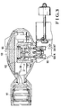
- Fig. 3 shows the main part of the analyzer portion of the thermal conductivity type hydrogen meter.
- reference numeral 100 denotes a case; 101, a main board; 102, an oven; 103, a gas inlet; and 104, a gas outlet.
- the heater 28 is embedded in the oven 102 to form the thermostat tank 27.
- the ⁇ TCD 105 in Fig. 2 is disposed in the central portion of the thermostat tank 27 such that the diaphragm portion 31 is directed toward the supply path for a sample gas.
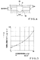
- Fig. 4 shows how the ⁇ TCD 105 is disposed in the thermostat tank 27 in Fig. 3.
- the volume of a chamber portion 106 facing the diaphragm portion 31 is set to be larger than that of a gas flow channel for reducing the influence of the flow of a gas.
- a sample gas is supplied to the TCD 21, and deprives the TCD 1 of heat in proportion to thermal conductivity.
- a voltage generated at the connection point between the resistor R1 and the TCD 21 is applied to the inverting input of the comparator 23, and a voltage generated at the connection point between the resistors R3 and R2 is applied to the non-inverting input of the comparator 23.
- Q T Q G + Q S + Q C + Q R
- Q G the quantity of heat transferred to the sample gas by thermal conduction
- Q S the quantity of heat transferred to the base 30 via the diaphragm portion
- Q C the quantity of heat transferred by convection (forced convection and unforced convection)
- Q R the quantity of heat transferred by radiation.
- Q T (T Rh - T RR2 ) ⁇ ⁇ m ⁇ G + (T Rh - T RR2 ) ⁇ ⁇ si ⁇ G S + Q C + Q R
- T RR2 is an ambient temperature (°C) around the base 30
- ⁇ m is the thermal conductivity (w/k ⁇ m) of the sample gas
- G is a device constant (m)
- ⁇ si is the thermal conductivity (w/k ⁇ m) of the diaphragm portion 31
- G S is a device constant (m) in the diaphragm portion 31.
- the device constant G and the device constant G S do not change regardless of the gas composition, and the quantities of heat Q C and Q R are values (or constant values) sufficiently smaller than those of the quantities of heat Q G and Q S .
- the thermal conductivity ⁇ si is considered as a constant value.
- the heating temperature T Rh is therefore controlled to be a constant value.
- the ambient temperature T RR2 is measured by the temperature sensor 22, and power to the heater 28 is controlled by the thermostat tank temperature control circuit 29 on the basis of the measured temperature. With this operation, the temperature in the thermostat tank 27 is adjusted, and the ambient temperature T RR2 around the base 30 is kept at a constant value.
- the heating temperature T Rh and the ambient temperature T RR2 are respectively kept at 140°C and 60°C. With this operation, the temperature difference between the heating temperature T Rh and the ambient temperature T RR2 is always kept at 80°C.
- Equation (3) can therefore be rewritten as equation (4):
- Q T A ⁇ ⁇ m + B
- a and B are device constants (shape factors including operation state factors).
- the thermal conductivity ⁇ m of the sample gas can be obtained by a substitution of the output voltage v into equation (6).
- equation (6) is set in the thermal conductivity calculating section 24.
- the device constants A and B in this mathematical expression are determined as follows.
- a first calibration gas e.g., 100% N 2 gas
- a second calibration gas e.g., 100% H 2 gas
- the measured output voltages v N2 and v H2 are then substituted into equations (7) and (8) to obtain the device constants A and B.
- the obtained device constants A and B are set as the device constants A and B in the mathematical expression set in the thermal conductivity calculating section 24.
- A (v N2 2 - v H2 2 )/Rh ⁇ ( ⁇ N2 - ⁇ H2 )
- B (v N2 2 ⁇ H2 - V H2 2 ⁇ N2 )/Rh ⁇ ( ⁇ H2 - ⁇ N2 )
- ⁇ N2 is the thermal conductivity (w/k ⁇ m) of 100% N 2 gas at (T Rh + T RR2 )/2
- ⁇ H2 is the thermal conductivity (w/k ⁇ m) of 100% H 2 gas at (T Rh + T RR2 )/2.
- T Rh and T RR2 are respectively kept at 140°C and 60°C
- T Rh + T RR2 )/2 100°C. Therefore, the thermal conductivities of the calibration gases, which have already been obtained as physical data at 100°C, can be used.
- v N2 2 Rh ⁇ A ⁇ N2 + Rh ⁇ B
- v H2 2 Rh ⁇ A ⁇ H2 + Rh ⁇ B
- a temperature sensor may be mounted in the thermostat tank 27 to keep the temperature in the thermostat tank 27 at 60°C. In this case, however, even if the temperature in the thermostat tank 27 is kept at 60°C, since different temperatures are measured at different measurement places, the ambient temperature T RR2 around the base 30 cannot be accurately kept at 60°C.
- the temperature sensor 22 is mounted in the base 30 to adjust the temperature in the thermostat tank 27 such that the measurement temperature of the temperature sensor 22 is kept at 60°C.
- the ambient temperature T RR2 around the base 30 is accurately kept at 60°C.
- a plurality of types of calibration curves commonly determined for all analyzers in accordance with measurement gases and carrier gases contained in a sample gas are stored in the ROM 26.
- various calibration curves stored in the ROM 26 include: an N 2 -H 2 calibration curve representing the H 2 concentration of a sample gas having a thermal conductivity ⁇ m and containing H 2 as a measurement gas and N 2 as a carrier gas in Fig.
- a calibration curve representing the H 2 concentration of a sample gas having a thermal conductivity ⁇ m and containing H 2 as a measurement gas and CH 4 as a carrier gas
- a calibration curve representing the H 2 concentration of a sample gas having a thermal conductivity ⁇ m and containing H 2 as a measurement gas and CO 2 as a carrier gas.
- these calibration curves are obtained as physical data in advance. If such calibration curves are not obtained in advance, they are created by actual measurement.
- the concentration output section 25 reads out a necessary calibration curve of the calibration curves stored in the ROM 26 in accordance with the composition of a sample gas in question.
- the N 2 -H 2 calibration curve is read out.
- the concentration of H 2 contained in the sample gas is obtained on the basis of the thermal conductivity ⁇ m of the sample gas which is calculated by the thermal conductivity calculating section 24. This concentration is then output as a measured concentration value.
- the concentration of a measurement gas can be measured without using an intrinsic calibration curve for each analyzer.
- the device constants A and B in the mathematical expression in the thermal conductivity calculating section 24 need only be determined on the basis of the output voltages v which are respectively measured by supplying the first and second calibration gases to the TCD 21. For this reason, the time required for calibration and adjustment of the analyzer can be greatly shortened.
- H 2 having a high thermal conductivity is used as a measurement gas.
- a gas having a high thermal conductivity e.g., He
- a gas having a low thermal conductivity e.g., Cl 2
- a measurement gas e.g., a measurement gas. That is, as long as the difference in thermal conductivity between a carrier gas and a measurement gas is large, the concentration of the measurement gas can be measured in the same manner as H 2 .
- 100% N 2 gas and 100% H 2 gas are respectively used as the first and second calibration gases, any gases can be used as calibration gases as long as their thermal conductivities are known.
- various calibration curves are stored in the ROM 26.
- the resistance value of the heating means i.e., heating temperature
- the resistance value of the heating means is controlled to be constant by using the Wheatstone bridge and the operational amplifier.
- the present invention is not limited to this.
- the resistance value of the heating means i.e., heating temperature
- the thermal conductivity ⁇ m of a sample gas is calculated by substituting the output voltage v into a predetermined mathematical expression (equation (6)).
- an intrinsic v- ⁇ m characteristic representing the relationship between the output voltage v and the thermal conductivity ⁇ m may be stored for each analyzer, and the thermal conductivity ⁇ m corresponding to the output voltage v may be obtained from the v- ⁇ m characteristic.
- the temperature in the thermostat tank 27 is adjusted such that the temperature measured by the temperature sensor 22 is kept at a constant value (60°C).
- a temperature sensor 22 may be connected between resistors R3 and R2, and the connection point between the resistor R3 and the temperature sensor 22 may be connected to the non-inverting input of a comparator 23.
- a current i flowing through a TCD 21 may be controlled such that the temperature difference between a heating temperature T Rh of the TCD 21 and an ambient temperature T RR2 around a base 30 becomes a constant value (80°C).
- the value of Rh changes.
- the ambient temperature T RR2 therefore, does not change much. For this reason, by using this circuit, the thermal conductivity ⁇ m of the sample gas can be obtained with relatively high precision without using a thermostat tank 27.
- R (T) R (20) ⁇ 1 + ⁇ (20) ⁇ (T - 20) + ⁇ (20) ⁇ (T - 20) 2 ⁇
- R (20) is the resistance value at 20 [°C]
- ⁇ (20) is the primary resistance temperature coefficient at 20 [°C]
- ⁇ (20) is the secondary resistance temperature coefficient at 20 [°C].
- Rh (t) Rh (20) ⁇ 1 + ⁇ (20) ⁇ (t - 20) + ⁇ (20) ⁇ (t - 20) 2 ⁇
- Rh (t) ⁇ R3 R1 ⁇ (RR2(T RR2 ) + R2)
- R3 (RR2(T RR2 ) + R2).
- the first to third embodiments have the following advantages as compared with prior art 1.
- the TCD 21 is formed as a platinum thin film resistive element inside the diaphragm portion 31, and a compact mounting structure is realized, the volume of the measurement cell is small, and gas replacement can be quickly performed. For this reason, good response characteristics are attained.
- the heating temperature T Rh of the TCD 21 is controlled to be kept at a constant value (the first and second embodiments), and the temperature difference between the heating temperature T Rh of the TCD 21 and the ambient temperature T RR2 is controlled to be kept at a constant value (the first to third embodiments), thermal drifts of the TCD 21 are small, and the time required to stabilize the temperature is very short, thus realizing good response characteristics.
- the TCD 21 is formed as a platinum thin film resistive element in the diaphragm portion 31, this device is resistant to vibrations, and disconnection does not easily occur.
- the heating temperature T Rh of the TCD 21 is controlled to be kept at a constant value (the first and second embodiments), and the temperature difference between the heating temperature T Rh of the TCD 21 and the ambient temperature T RR2 is controlled to be kept at a constant value (the first to third embodiments), the TCD 21 undergoes a small temperature change, and is free from large thermal stress. In addition, resistance drifts and degradation are small, and the service life is long.
- the diaphragm portion 31 is free from large thermal stress, and is protected. That is, since the diaphragm portion 31 has a three-layer structure, large thermal stress on the diaphragm portion 31 may cause peeling or deformation of the layers. In this embodiment, however, since no large thermal stress acts on the diaphragm portion 31, peeling or deformation of the layers does not occur.
- the thermal conductivity ⁇ m of a sample gas can be obtained with high precision. Since the thermal conductivity is a function of temperature, it is important to specify a temperature at which measurement is performed. In prior art 1, since the difference between the temperature of the TCD and the ambient temperature around the TCD changes, the thermal conductivity at a specific temperature cannot be measured, resulting in poor precision. In this embodiment, however, since the temperature difference between the heating temperature T Rh and the ambient temperature T RR2 is controlled to be a constant value, the thermal conductivity at a specific temperature can be measured. This allows high-precision measurement.
- the first to third embodiments described above have the following advantages as compared with prior art 2.
- the TCD 21 is formed as a platinum thin film resistive element inside the diaphragm portion 31, and a compact mounting structure is realized, the volume of the measurement cell is small, and gas replacement can be quickly performed. For this reason, good response characteristics are attained.
- the TCD 21 is formed as a platinum thin film resistive element in the diaphragm portion 31, this device is resistant to vibrations, and disconnection does not easily occur.
- the thermal conductivity ⁇ m of a sample gas can be obtained with high precision.
- the heating temperature T Rh can be stably controlled to a constant temperature (the first and second embodiments).
- the temperature difference between the heating temperature T Rh and the ambient temperature T RR2 can be controlled to a predetermined value (the first to third embodiments), and control of the heating temperature T Rh of the TCD 21 does not interfere with control of the ambient temperature T RR2 around the base 30.
- the TCD 21 is formed inside the diaphragm portion 31 on the base 30 to be parallel to a gas flow in the chamber portion 106, the influence of a gas flow is small, and the thermal conductivity ⁇ m of a sample gas can be obtained with high precision.
- the first to third embodiments described above have the following advantages as compared with prior art 3.
- the TCD 21 is formed as a platinum thin film resistive element inside the diaphragm portion 31, and a compact mounting structure is realized, the volume of the measurement cell is small, and gas replacement can be quickly performed. For this reason, good response characteristics are attained.
- the heating temperature T Rh of the TCD 21 is controlled to be kept at a constant value (the first and second embodiments), and the temperature difference between the heating temperature T Rh of the TCD 21 and the ambient temperature T RR2 is controlled to be kept at a constant value (the first to third embodiments), thermal drifts of the TCD 21 are small, and the time required to stabilize the temperature is very short, thus realizing good response characteristics.
- the TCD 21 is formed as a platinum thin film resistive element in the diaphragm portion 31, this device is resistant to vibrations, and disconnection does not easily occur. In addition, since the TCD 21 is on a plane of the base 30 to be parallel to a gas flow, the TCD 21 does not receive fluid resistance much.
- the heating temperature T Rh of the TCD 21 is controlled to be kept at a constant value (the first and second embodiments), and the temperature difference between the heating temperature T Rh of the TCD 21 and the ambient temperature T RR2 is controlled to be kept at a constant value (the first to third embodiments), the TCD 21 undergoes a small temperature change, and is free from large thermal stress. In addition, resistance drifts are small, and the service life is long.
- the diaphragm portion 31 is free from large thermal stress, and is protected.
- the thermal conductivity ⁇ m of a sample gas can be obtained with high precision.
- City gas mainly consisting of a liquefied natural gas as a measurement gas is a lower hydrocarbon mixture mainly consisting of methane.
- Table 1 shows the composition of this mixture. Referring to Table 1, the thermal conductivities are measured at a gas temperature of 114°C.
- Table 1 Hydrocarbon Standard Concentration (%) Concentration Range (%) Calorific Value (kcal/N ⁇ m 3 ) Thermal Conductivity (mW/m ⁇ K) CH 4 88.8 60.0 - 99.8 9540 47.3396 C 2 H 6 5.6 0.08 - 40.0 16830 34.078 C 3 H 8 3.7 0.01 - 5.0 24220 28.714 iC 4 H 10 1.8 2.5 or less 31790 25.963 others 0.1 -
- the calorific value of this measurement gas as a sample gas changes within the range of 9,500 to 12,000 kcal/N ⁇ m 3 .
- the calorific value of the city gas mainly consisting of the natural gas made of the above components is about 11,000 kcal/Nm 3 .
- the relationship between the calorific value and thermal conductivity of the city gas can be approximated by a straight line connecting the thermal conductivities and calorific values of methane and ethane near the above calorific value. Equation (24) described above represents the straight line connecting the thermal conductivities and calorific values of methane and ethane.
- equation (25) as an approximation expression is established by the least squares method, thereby improving the precision.
- H -516.52 x ⁇ m + 33988.4 (kcal/N ⁇ m 3 )
- Table 3 shows the measurement results of the sample gases in Table 2, which were obtained by using equation (25). The maximum error was 30 kcal/Nm 3 .
- Table 3 Gas Thermal Conductivity (mW/m ⁇ K) Calculated Calorific Value (kcal/Nm 3 ) Error (kcal/Nm 3 ) CH 4 47.3396 9536 -4 No. 1 46.9492 9738 -17 No. 2 46.3643 10040 -13 No. 3 46.999 10745 -28 No. 4 44.687 10906 +26
- the heating means when a sample gas is supplied to the heating means (TCD) formed inside the diaphragm portion formed on the base, the heating means is deprived of heat proportional to the thermal conductivity of the gas.
- the amount of energy supplied to the heating means is controlled to keep the heating temperature of the heating means at a constant value, and the ambient temperature measured by the ambient temperature measuring means disposed on the base is kept at a constant value. While the ambient temperature and the heating temperature are kept at the constant values, the thermal conductivity of the sample gas is obtained on the basis of the amount of energy supplied to the heating means. Fast response and long service life can be attained. In addition, the thermal conductivity can be obtained with high precision.
- the thermal conductivity of the sample gas is calculated by substituting the output voltage v , which is the voltage across the two ends of the heating elements while the ambient temperature and the heating temperature are kept at constant values, into a predetermined mathematical expression. For this reason, the output voltage/thermal conductivity characteristics need not be stored, and hence the memory capacity can be reduced.
- the device constants in the mathematical expression need only be determined on the output voltages v measured by supplying first and second calibration gases to the heating means. For this reason, the time required for calibration and adjustment of the thermal conductivity type gas analyzer can be greatly shortened as compared with the conventional devices.
- the ambient temperature and the heating temperature are respectively kept at 60°C and 140°C.
- the thermal conductivities of the calibration gases which are obtained as physical data in advance at 100°C can be used.
- the thermal conductivity of the sample gas is obtained on the basis of the amount of energy supplied to the heating means while the ambient temperature and the heating temperature are kept at the constant values; fast response and long service life can be attained. Furthermore, the thermal conductivity can be obtained with high precision.
- the calorific value of a measurement gas can be obtained by measuring its thermal conductivity.
- the thermal conductivity scarcely changes within the pressure range near the atmospheric pressure.
- this measurement is performed in a thermostat tank. For this reason, this device is not easily influenced by the surroundings and the measurement gas atmosphere, and hence can continuously measure the calorific value of the measurement gas.
Landscapes
- Chemical & Material Sciences (AREA)
- Analytical Chemistry (AREA)
- Electrochemistry (AREA)
- Physics & Mathematics (AREA)
- Health & Medical Sciences (AREA)
- Life Sciences & Earth Sciences (AREA)
- Chemical Kinetics & Catalysis (AREA)
- Biochemistry (AREA)
- General Health & Medical Sciences (AREA)
- General Physics & Mathematics (AREA)
- Immunology (AREA)
- Pathology (AREA)
- Investigating Or Analyzing Materials Using Thermal Means (AREA)
- Investigating Or Analyzing Materials By The Use Of Electric Means (AREA)
Applications Claiming Priority (2)
| Application Number | Priority Date | Filing Date | Title |
|---|---|---|---|
| JP8970/95 | 1995-01-24 | ||
| JP07008970A JP3114139B2 (ja) | 1995-01-24 | 1995-01-24 | 熱伝導率計 |
Publications (2)
| Publication Number | Publication Date |
|---|---|
| EP0724151A1 true EP0724151A1 (de) | 1996-07-31 |
| EP0724151B1 EP0724151B1 (de) | 1999-04-07 |
Family
ID=11707550
Family Applications (1)
| Application Number | Title | Priority Date | Filing Date |
|---|---|---|---|
| EP96300221A Expired - Lifetime EP0724151B1 (de) | 1995-01-24 | 1996-01-11 | Gerät zur Messung der Wärmeleitfähigkeit |
Country Status (6)
| Country | Link |
|---|---|
| US (1) | US5756878A (de) |
| EP (1) | EP0724151B1 (de) |
| JP (1) | JP3114139B2 (de) |
| AU (1) | AU693301B2 (de) |
| CA (1) | CA2166956C (de) |
| DE (1) | DE69601953T2 (de) |
Cited By (8)
| Publication number | Priority date | Publication date | Assignee | Title |
|---|---|---|---|---|
| GB2340945A (en) * | 1998-08-25 | 2000-03-01 | British Gas Plc | Measuring volume and calorific value to determine an energy value of supplied gas |
| WO2000058723A2 (en) * | 1999-03-30 | 2000-10-05 | The Regents Of The University Of California | Micro-machined thermal conductivity detector |
| WO2003027654A2 (de) * | 2001-09-20 | 2003-04-03 | Robert Bosch Gmbh | Sensorbaustein mit einem sensorelement, das von einem heizelement umgeben ist |
| WO2003054534A3 (en) * | 2001-12-20 | 2003-12-04 | Honeywell Int Inc | Fluid mixture composition sensor |
| EP1645870A1 (de) * | 2003-07-11 | 2006-04-12 | Mitsui Mining & Smelting Co., Ltd | Typenidentifizierungssystem für dieselöl und verfahren zur identifizierung des dieselöltyps |
| CN105510493A (zh) * | 2014-10-10 | 2016-04-20 | 株式会社岛津制作所 | 导热系数检测器和气相色谱仪 |
| EP3096137A1 (de) * | 2015-05-20 | 2016-11-23 | Siemens Aktiengesellschaft | Wärmeleitfähigkeitsdetektor und detektormodul |
| EP4227755A1 (de) * | 2022-02-11 | 2023-08-16 | Shenzhen Cambri Environmental Technology Co. Ltd. | Kompakte gasmessgeräte und thermostatisches modul davon |
Families Citing this family (52)
| Publication number | Priority date | Publication date | Assignee | Title |
|---|---|---|---|---|
| US7133726B1 (en) * | 1997-03-28 | 2006-11-07 | Applera Corporation | Thermal cycler for PCR |
| DE19757258C2 (de) * | 1997-12-23 | 2001-02-08 | Heraeus Electro Nite Int | Sensor mit temperaturabhängigem Meßwiderstand und dessen Verwendung zur Temperaturmessung |
| US6422743B1 (en) | 1999-03-26 | 2002-07-23 | Allison Advanced Development Company | Method for determining heat transfer performance of an internally cooled structure |
| IT1312311B1 (it) * | 1999-05-07 | 2002-04-15 | Thermoquest Italia Spa | Dispositivo per la misurazione della conducibilita' termica di unfluido |
| FR2794243B1 (fr) * | 1999-05-28 | 2001-07-13 | Commissariat Energie Atomique | Dispositif de mesure de la concentration en hydrogene dans un melange gazeux |
| JP3444252B2 (ja) * | 1999-12-17 | 2003-09-08 | 株式会社島津製作所 | 熱伝導度検出器 |
| DE10144343A1 (de) * | 2001-09-10 | 2003-03-27 | Perkinelmer Optoelectronics | Sensor zum berührugslosen Messen einer Temperatur |
| DE10249935A1 (de) * | 2002-10-24 | 2004-05-13 | Abb Research Ltd. | Verfahren und Vorrichtung zur Auswertung von Messsignalen |
| JP4047272B2 (ja) * | 2003-12-26 | 2008-02-13 | アルプス電気株式会社 | 水素センサおよび水素濃度測定装置、水素濃度測定方法 |
| WO2006020814A2 (en) * | 2004-08-10 | 2006-02-23 | Robertshaw Controls Company | Pressure and temperature measurement of a piezo-resistive device using differential channel of a ratiometric analog to digital converter |
| US7483795B2 (en) * | 2004-08-10 | 2009-01-27 | Robertshaw Controls Company | Pressure and temperature compensation algorithm for use with a piezo-resistive strain gauge type pressure sensor |
| US7191072B2 (en) * | 2004-08-10 | 2007-03-13 | Robertshaw Controls Company | Pressure and temperature measurement of a piezo-resistive device using differential channel of a ratiometric analog to digital converter |
| EP1946099A2 (de) | 2005-09-02 | 2008-07-23 | ABB, Inc. | Modularer gaschromatograph |
| JP4868604B2 (ja) * | 2005-09-27 | 2012-02-01 | 株式会社山武 | 熱伝導率測定装置、ガス成分比率測定装置 |
| WO2007036983A1 (ja) * | 2005-09-27 | 2007-04-05 | Yamatake Corporation | 熱伝導率測定方法および装置、並びにガス成分比率測定装置 |
| CN1948957A (zh) * | 2005-10-13 | 2007-04-18 | 鸿富锦精密工业(深圳)有限公司 | 流质材料热传导性能量测装置 |
| JP4505842B2 (ja) * | 2006-03-15 | 2010-07-21 | 株式会社山武 | 熱伝導率測定方法とその装置およびガス成分比率測定装置 |
| GB0605683D0 (en) * | 2006-03-21 | 2006-05-03 | Servomex Group Ltd | Thermal conductivity sensor |
| US20080291966A1 (en) * | 2007-05-24 | 2008-11-27 | Engel Steven J | Thermal conductivity detector (TCD) having compensated constant temperature element |
| US7670046B2 (en) * | 2007-06-18 | 2010-03-02 | Iliya Mitov | Filled hotwire elements and sensors for thermal conductivity detectors |
| US8047712B1 (en) * | 2007-07-26 | 2011-11-01 | Lockheed Martin Corporation | Method and apparatus for predicting steady state temperature of solid state devices |
| US7824099B2 (en) * | 2007-11-29 | 2010-11-02 | Gm Global Technology Operations, Inc. | Accurate gas temperature estimation at transient conditions based on temperature sensor readings |
| US8968560B2 (en) * | 2007-12-06 | 2015-03-03 | Schlumberger Technology Corporation | Chromatography using multiple detectors |
| CN102165309A (zh) * | 2008-10-01 | 2011-08-24 | 株式会社山武 | 发热量计算式制作系统、发热量计算式的制作方法、发热量计算系统以及发热量的计算方法 |
| JP5165627B2 (ja) * | 2009-03-30 | 2013-03-21 | アズビル株式会社 | 物性値測定システム及び物性値測定方法 |
| JP5192431B2 (ja) * | 2009-03-31 | 2013-05-08 | アズビル株式会社 | ガス物性値測定システム |
| US8762075B2 (en) * | 2009-09-29 | 2014-06-24 | Lawrence Livermore National Security, Llc | Microcantilever-based gas sensor employing two simultaneous physical sensing modes |
| FI20096021A0 (fi) * | 2009-10-06 | 2009-10-06 | Wallac Oy | Optinen mittausinstrumentti |
| JP5420456B2 (ja) * | 2010-03-17 | 2014-02-19 | アズビル株式会社 | 発熱量算出式作成システム、発熱量算出式の作成方法、発熱量測定システム、及び発熱量の測定方法 |
| JP5421832B2 (ja) * | 2010-03-25 | 2014-02-19 | アズビル株式会社 | 発熱量算出式作成システム、発熱量算出式の作成方法、発熱量測定システム、及び発熱量の測定方法 |
| JP5335722B2 (ja) * | 2010-03-26 | 2013-11-06 | アズビル株式会社 | 発熱量算出式作成システム、発熱量算出式の作成方法、発熱量測定システム、及び発熱量の測定方法 |
| JP5335727B2 (ja) * | 2010-03-29 | 2013-11-06 | アズビル株式会社 | 発熱量算出式作成システム、発熱量算出式の作成方法、発熱量測定システム、及び発熱量の測定方法 |
| US9128028B2 (en) * | 2010-07-29 | 2015-09-08 | Honeywell International Inc. | Thermal conductivity detectors |
| JP5641996B2 (ja) * | 2011-03-24 | 2014-12-17 | アズビル株式会社 | 密度測定システム及び密度の測定方法 |
| JP5759780B2 (ja) | 2011-05-09 | 2015-08-05 | アズビル株式会社 | 発熱量測定システム及び発熱量の測定方法 |
| EP2554980B1 (de) | 2011-08-03 | 2014-06-25 | Nxp B.V. | Integrierte Schaltung mit Sensor und Verfahren zur Herstellung solch einer integrierten Schaltung |
| EP2559996B1 (de) | 2011-08-16 | 2017-11-22 | Nxp B.V. | Gassensor |
| EP2639583A1 (de) * | 2012-03-12 | 2013-09-18 | Mettler-Toledo AG | Funktionsüberprüfung von Wärmeleitfähigkeits-Gassensoren |
| JP5781968B2 (ja) | 2012-03-27 | 2015-09-24 | アズビル株式会社 | 発熱量測定システム及び発熱量の測定方法 |
| US9121773B2 (en) * | 2013-03-13 | 2015-09-01 | Bascom-Turner Instruments | Gas sensors and methods of calibrating same |
| DE112013006685B4 (de) * | 2013-03-13 | 2022-06-15 | Bascom-Turner Instruments, Inc. | Gassensoren, Verfahren und Vorrichtung zur Kalibrierung derselben |
| US9228983B2 (en) * | 2013-03-14 | 2016-01-05 | Rosemount Analytical Inc. | Process analytic device with improved thermal stability |
| US9671180B2 (en) | 2013-03-14 | 2017-06-06 | Rosemount Analytical, Inc | Process analytic device with improved thermal stability |
| DE102013103388B3 (de) * | 2013-04-05 | 2014-09-25 | Chemec Gmbh | Vorrichtung für die Messung der Wärmeleitfähigkeit von Gaskomponenten eines Gasgemisches |
| US9612146B2 (en) | 2014-02-07 | 2017-04-04 | Honeywell International, Inc. | Airflow sensor with dust reduction |
| US9453807B2 (en) | 2014-04-08 | 2016-09-27 | Ams International Ag | Thermal conductivity gas sensor with amplification material |
| EP2933635B1 (de) | 2014-04-14 | 2016-06-01 | Siemens Aktiengesellschaft | Wärmeleitfähigkeitsdetektorschaltung und Betriebsverfahren dafür |
| EP2933919A1 (de) | 2014-04-14 | 2015-10-21 | Siemens Aktiengesellschaft | Wärmeleitfähigkeitsdetektorschaltung und Betriebsverfahren dafür |
| EP2933634A1 (de) | 2014-04-14 | 2015-10-21 | Siemens Aktiengesellschaft | Wärmeleitfähigkeitsdetektor |
| EP3093659B1 (de) | 2015-05-11 | 2017-06-14 | Siemens Aktiengesellschaft | Wärmeleitfähigkeitsdetektor und verfahren zum betrieb davon |
| CN109709133A (zh) * | 2017-10-25 | 2019-05-03 | 天津市业洪检测技术发展有限公司 | 一种大流量低扰动恒温痕量热导检测器 |
| CN108844639B (zh) * | 2018-04-12 | 2019-10-01 | 昆山光微电子有限公司 | 电读出非制冷红外探测器的测试电路与方法 |
Citations (6)
| Publication number | Priority date | Publication date | Assignee | Title |
|---|---|---|---|---|
| DE2209413A1 (de) * | 1972-02-28 | 1973-09-06 | Helmut Dipl Chem Ulrich | Verfahren bzw. einrichtung zur messung physikalischer groessen, beispielsweise von temperatur oder strahlung oder stroemungsmenge oder waermeleitfaehigkeit, mittels temperaturabhaengiger, von einem elektrischen strom durchflossener messwiderstaende |
| US4706061A (en) * | 1986-08-28 | 1987-11-10 | Honeywell Inc. | Composition sensor with minimal non-linear thermal gradients |
| DE3711511C1 (de) * | 1987-04-04 | 1988-06-30 | Hartmann & Braun Ag | Verfahren zur Bestimmung der Gaskonzentrationen in einem Gasgemisch und Sensor zur Messung der Waermeleitfaehigkeit |
| EP0382414A2 (de) * | 1989-02-06 | 1990-08-16 | Alcan International Limited | Verfahren und Vorrichtung zur Messung der Wärmeleitfähigkeit von Gasen |
| US5303167A (en) * | 1991-03-08 | 1994-04-12 | Honeywell Inc. | Absolute pressure sensor and method |
| US5377527A (en) * | 1992-09-14 | 1995-01-03 | Yamatake-Honeywell Co., Ltd. | Thermal conductivity measuring device |
Family Cites Families (14)
| Publication number | Priority date | Publication date | Assignee | Title |
|---|---|---|---|---|
| US4080821A (en) * | 1977-03-28 | 1978-03-28 | Rosemount Engineering Company Limited | Electric circuits |
| US4471647A (en) * | 1980-04-18 | 1984-09-18 | Board Of Regents Of Stanford University | Gas chromatography system and detector and method |
| JPS58202863A (ja) * | 1982-05-21 | 1983-11-26 | Shisaka Kenkyusho:Kk | 二定温度式熱伝導度測定セル |
| DE3502440A1 (de) * | 1985-01-25 | 1986-07-31 | Leybold-Heraeus GmbH, 5000 Köln | Anordnung zur messung der waermeleitfaehigkeit von gasen |
| US4682503A (en) * | 1986-05-16 | 1987-07-28 | Honeywell Inc. | Microscopic size, thermal conductivity type, air or gas absolute pressure sensor |
| EP0316498B1 (de) * | 1987-11-09 | 1992-03-04 | Vibro-Meter Sa | Accelerometer |
| US4956793A (en) * | 1988-06-24 | 1990-09-11 | Honeywell Inc. | Method and apparatus for measuring the density of fluids |
| US4944035A (en) * | 1988-06-24 | 1990-07-24 | Honeywell Inc. | Measurement of thermal conductivity and specific heat |
| US4880714A (en) * | 1989-02-27 | 1989-11-14 | Duracell Inc. | Method for preparing non-aqueous electrolytes |
| US5237523A (en) * | 1990-07-25 | 1993-08-17 | Honeywell Inc. | Flowmeter fluid composition and temperature correction |
| EP0484645B1 (de) * | 1990-11-09 | 1995-04-26 | Hewlett-Packard Company | Verfahren und Systeme zur Identifizierung von Flüssigkeiten und Bestimmung der Strömung |
| JP2992848B2 (ja) * | 1991-08-21 | 1999-12-20 | 株式会社山武 | 熱伝導率検出器 |
| US5463899A (en) * | 1994-08-12 | 1995-11-07 | Gas Research Institute | Simultaneous measurement of gas thermal conductivity and mass flow |
| US5515714A (en) * | 1994-11-17 | 1996-05-14 | General Motors Corporation | Vapor composition and flow sensor |
-
1995
- 1995-01-24 JP JP07008970A patent/JP3114139B2/ja not_active Expired - Fee Related
-
1996
- 1996-01-10 CA CA002166956A patent/CA2166956C/en not_active Expired - Fee Related
- 1996-01-11 DE DE69601953T patent/DE69601953T2/de not_active Expired - Lifetime
- 1996-01-11 EP EP96300221A patent/EP0724151B1/de not_active Expired - Lifetime
- 1996-01-16 US US08/585,770 patent/US5756878A/en not_active Expired - Fee Related
- 1996-01-22 AU AU42118/96A patent/AU693301B2/en not_active Ceased
Patent Citations (6)
| Publication number | Priority date | Publication date | Assignee | Title |
|---|---|---|---|---|
| DE2209413A1 (de) * | 1972-02-28 | 1973-09-06 | Helmut Dipl Chem Ulrich | Verfahren bzw. einrichtung zur messung physikalischer groessen, beispielsweise von temperatur oder strahlung oder stroemungsmenge oder waermeleitfaehigkeit, mittels temperaturabhaengiger, von einem elektrischen strom durchflossener messwiderstaende |
| US4706061A (en) * | 1986-08-28 | 1987-11-10 | Honeywell Inc. | Composition sensor with minimal non-linear thermal gradients |
| DE3711511C1 (de) * | 1987-04-04 | 1988-06-30 | Hartmann & Braun Ag | Verfahren zur Bestimmung der Gaskonzentrationen in einem Gasgemisch und Sensor zur Messung der Waermeleitfaehigkeit |
| EP0382414A2 (de) * | 1989-02-06 | 1990-08-16 | Alcan International Limited | Verfahren und Vorrichtung zur Messung der Wärmeleitfähigkeit von Gasen |
| US5303167A (en) * | 1991-03-08 | 1994-04-12 | Honeywell Inc. | Absolute pressure sensor and method |
| US5377527A (en) * | 1992-09-14 | 1995-01-03 | Yamatake-Honeywell Co., Ltd. | Thermal conductivity measuring device |
Cited By (16)
| Publication number | Priority date | Publication date | Assignee | Title |
|---|---|---|---|---|
| GB2340945A (en) * | 1998-08-25 | 2000-03-01 | British Gas Plc | Measuring volume and calorific value to determine an energy value of supplied gas |
| GB2340945B (en) * | 1998-08-25 | 2002-12-31 | British Gas Plc | Measuring energy consumption |
| WO2000058723A2 (en) * | 1999-03-30 | 2000-10-05 | The Regents Of The University Of California | Micro-machined thermal conductivity detector |
| WO2000058723A3 (en) * | 1999-03-30 | 2001-01-11 | Univ California | Micro-machined thermal conductivity detector |
| US6502983B2 (en) | 1999-03-30 | 2003-01-07 | The Regents Of The University Of California | Micro-machined thermo-conductivity detector |
| WO2003027654A2 (de) * | 2001-09-20 | 2003-04-03 | Robert Bosch Gmbh | Sensorbaustein mit einem sensorelement, das von einem heizelement umgeben ist |
| WO2003027654A3 (de) * | 2001-09-20 | 2003-10-16 | Bosch Gmbh Robert | Sensorbaustein mit einem sensorelement, das von einem heizelement umgeben ist |
| US7165441B2 (en) | 2001-09-20 | 2007-01-23 | Robert Bosch Gmbh | Sensor module having a sensor element surrounded by a heating element |
| US6838287B2 (en) | 2001-12-20 | 2005-01-04 | Honeywell International Inc. | Fluid mixture composition sensor |
| WO2003054534A3 (en) * | 2001-12-20 | 2003-12-04 | Honeywell Int Inc | Fluid mixture composition sensor |
| EP1645870A1 (de) * | 2003-07-11 | 2006-04-12 | Mitsui Mining & Smelting Co., Ltd | Typenidentifizierungssystem für dieselöl und verfahren zur identifizierung des dieselöltyps |
| EP1645870A4 (de) * | 2003-07-11 | 2011-07-27 | Mitsui Mining & Smelting Co | Typenidentifizierungssystem für dieselöl und verfahren zur identifizierung des dieselöltyps |
| CN105510493A (zh) * | 2014-10-10 | 2016-04-20 | 株式会社岛津制作所 | 导热系数检测器和气相色谱仪 |
| EP3096137A1 (de) * | 2015-05-20 | 2016-11-23 | Siemens Aktiengesellschaft | Wärmeleitfähigkeitsdetektor und detektormodul |
| US10060866B2 (en) | 2015-05-20 | 2018-08-28 | Siemens Aktiengesellschaft | Thermal conductivity detector and detector module |
| EP4227755A1 (de) * | 2022-02-11 | 2023-08-16 | Shenzhen Cambri Environmental Technology Co. Ltd. | Kompakte gasmessgeräte und thermostatisches modul davon |
Also Published As
| Publication number | Publication date |
|---|---|
| CA2166956C (en) | 1999-07-06 |
| DE69601953T2 (de) | 1999-12-02 |
| JPH08201327A (ja) | 1996-08-09 |
| US5756878A (en) | 1998-05-26 |
| DE69601953D1 (de) | 1999-05-12 |
| AU693301B2 (en) | 1998-06-25 |
| EP0724151B1 (de) | 1999-04-07 |
| CA2166956A1 (en) | 1996-07-25 |
| AU4211896A (en) | 1996-08-01 |
| JP3114139B2 (ja) | 2000-12-04 |
Similar Documents
| Publication | Publication Date | Title |
|---|---|---|
| EP0724151A1 (de) | Gerät zur Messung der Wärmeleitfähigkeit | |
| US7647843B2 (en) | Universal sensor controller for a thermal anemometer | |
| US3425277A (en) | Electrical thermal flowmeter | |
| US4984460A (en) | Mass flowmeter | |
| EP0240637A1 (de) | Elektrische Methode zum Korrigieren von Fehlern, die bei Luftmassendurchflusssensoren vom Brückentyp auftreten und von Schwankungen der Umgebungstemperatur herrühren | |
| US5081869A (en) | Method and apparatus for the measurement of the thermal conductivity of gases | |
| JPH0868684A (ja) | 流量センサの較正方法および装置 | |
| US4688424A (en) | Apparatus for measuring air quantity | |
| US4850714A (en) | Apparatus for measuring the thermal conductivity of gases | |
| EP3540382B1 (de) | Luftstromsensor mit korrektur der gaszusammensetzung | |
| US20040211253A1 (en) | Thermal type flow measuring device | |
| US5494826A (en) | Microcalorimeter sensor for the measurement of heat content of natural gas | |
| US4056975A (en) | Mass flow sensor system | |
| EP0314919B1 (de) | Detektor für brennbare Gase mit Temperaturstabilisierung | |
| US2633737A (en) | Gas analyzer for plural mixtures | |
| US4918974A (en) | Method and apparatus for the measurement of the thermal conductivity of gases | |
| EP0172440B1 (de) | Heissdrahtgerät zur Durchflussmessung | |
| US4845984A (en) | Temperature compensation for a thermal mass flow meter | |
| KR960006308B1 (ko) | 감열식 유량센서 | |
| US5952571A (en) | Thermal type flow meter | |
| US20030115951A1 (en) | Apparatus and method for thermal isolation of thermal mass flow sensor | |
| US3007333A (en) | Gas analyzer apparatus | |
| US4220039A (en) | Fluid temperature compensator circuit for a thermal gauge probe | |
| US6338271B1 (en) | Device and process for measuring the velocity of flow of a fluid | |
| JPH0854268A (ja) | 質量流量センサ |
Legal Events
| Date | Code | Title | Description |
|---|---|---|---|
| PUAI | Public reference made under article 153(3) epc to a published international application that has entered the european phase |
Free format text: ORIGINAL CODE: 0009012 |
|
| 17P | Request for examination filed |
Effective date: 19960520 |
|
| AK | Designated contracting states |
Kind code of ref document: A1 Designated state(s): DE FR GB NL |
|
| 17Q | First examination report despatched |
Effective date: 19961129 |
|
| GRAG | Despatch of communication of intention to grant |
Free format text: ORIGINAL CODE: EPIDOS AGRA |
|
| GRAG | Despatch of communication of intention to grant |
Free format text: ORIGINAL CODE: EPIDOS AGRA |
|
| GRAH | Despatch of communication of intention to grant a patent |
Free format text: ORIGINAL CODE: EPIDOS IGRA |
|
| GRAH | Despatch of communication of intention to grant a patent |
Free format text: ORIGINAL CODE: EPIDOS IGRA |
|
| GRAA | (expected) grant |
Free format text: ORIGINAL CODE: 0009210 |
|
| RAP1 | Party data changed (applicant data changed or rights of an application transferred) |
Owner name: YAMATAKE CORPORATION |
|
| AK | Designated contracting states |
Kind code of ref document: B1 Designated state(s): DE FR GB NL |
|
| REF | Corresponds to: |
Ref document number: 69601953 Country of ref document: DE Date of ref document: 19990512 |
|
| ET | Fr: translation filed | ||
| PLBE | No opposition filed within time limit |
Free format text: ORIGINAL CODE: 0009261 |
|
| STAA | Information on the status of an ep patent application or granted ep patent |
Free format text: STATUS: NO OPPOSITION FILED WITHIN TIME LIMIT |
|
| 26N | No opposition filed | ||
| REG | Reference to a national code |
Ref country code: GB Ref legal event code: IF02 |
|
| PGFP | Annual fee paid to national office [announced via postgrant information from national office to epo] |
Ref country code: GB Payment date: 20070110 Year of fee payment: 12 |
|
| PGFP | Annual fee paid to national office [announced via postgrant information from national office to epo] |
Ref country code: NL Payment date: 20070115 Year of fee payment: 12 |
|
| PGFP | Annual fee paid to national office [announced via postgrant information from national office to epo] |
Ref country code: FR Payment date: 20070109 Year of fee payment: 12 |
|
| GBPC | Gb: european patent ceased through non-payment of renewal fee |
Effective date: 20080111 |
|
| NLV4 | Nl: lapsed or anulled due to non-payment of the annual fee |
Effective date: 20080801 |
|
| PG25 | Lapsed in a contracting state [announced via postgrant information from national office to epo] |
Ref country code: NL Free format text: LAPSE BECAUSE OF NON-PAYMENT OF DUE FEES Effective date: 20080801 |
|
| REG | Reference to a national code |
Ref country code: FR Ref legal event code: ST Effective date: 20081029 |
|
| PG25 | Lapsed in a contracting state [announced via postgrant information from national office to epo] |
Ref country code: GB Free format text: LAPSE BECAUSE OF NON-PAYMENT OF DUE FEES Effective date: 20080111 |
|
| PG25 | Lapsed in a contracting state [announced via postgrant information from national office to epo] |
Ref country code: FR Free format text: LAPSE BECAUSE OF NON-PAYMENT OF DUE FEES Effective date: 20080131 |
|
| PGFP | Annual fee paid to national office [announced via postgrant information from national office to epo] |
Ref country code: DE Payment date: 20100107 Year of fee payment: 15 |
|
| REG | Reference to a national code |
Ref country code: DE Ref legal event code: R119 Ref document number: 69601953 Country of ref document: DE Effective date: 20110802 |
|
| PG25 | Lapsed in a contracting state [announced via postgrant information from national office to epo] |
Ref country code: DE Free format text: LAPSE BECAUSE OF NON-PAYMENT OF DUE FEES Effective date: 20110802 |