EP0240637A1 - Elektrische Methode zum Korrigieren von Fehlern, die bei Luftmassendurchflusssensoren vom Brückentyp auftreten und von Schwankungen der Umgebungstemperatur herrühren - Google Patents
Elektrische Methode zum Korrigieren von Fehlern, die bei Luftmassendurchflusssensoren vom Brückentyp auftreten und von Schwankungen der Umgebungstemperatur herrühren Download PDFInfo
- Publication number
- EP0240637A1 EP0240637A1 EP86309547A EP86309547A EP0240637A1 EP 0240637 A1 EP0240637 A1 EP 0240637A1 EP 86309547 A EP86309547 A EP 86309547A EP 86309547 A EP86309547 A EP 86309547A EP 0240637 A1 EP0240637 A1 EP 0240637A1
- Authority
- EP
- European Patent Office
- Prior art keywords
- flow rate
- signal
- temperature
- air flow
- error
- Prior art date
- Legal status (The legal status is an assumption and is not a legal conclusion. Google has not performed a legal analysis and makes no representation as to the accuracy of the status listed.)
- Granted
Links
Images
Classifications
-
- G—PHYSICS
- G01—MEASURING; TESTING
- G01F—MEASURING VOLUME, VOLUME FLOW, MASS FLOW OR LIQUID LEVEL; METERING BY VOLUME
- G01F1/00—Measuring the volume flow or mass flow of fluid or fluent solid material wherein the fluid passes through a meter in a continuous flow
- G01F1/68—Measuring the volume flow or mass flow of fluid or fluent solid material wherein the fluid passes through a meter in a continuous flow by using thermal effects
- G01F1/696—Circuits therefor, e.g. constant-current flow meters
- G01F1/698—Feedback or rebalancing circuits, e.g. self heated constant temperature flowmeters
-
- G—PHYSICS
- G01—MEASURING; TESTING
- G01F—MEASURING VOLUME, VOLUME FLOW, MASS FLOW OR LIQUID LEVEL; METERING BY VOLUME
- G01F1/00—Measuring the volume flow or mass flow of fluid or fluent solid material wherein the fluid passes through a meter in a continuous flow
- G01F1/68—Measuring the volume flow or mass flow of fluid or fluent solid material wherein the fluid passes through a meter in a continuous flow by using thermal effects
- G01F1/696—Circuits therefor, e.g. constant-current flow meters
- G01F1/6965—Circuits therefor, e.g. constant-current flow meters comprising means to store calibration data for flow signal calculation or correction
Definitions
- This invention relates to mass flow rate sensors and more particularly to an improved method and circuit for a metal foil bridge type mass air flow rate sensor with so-called TCOMP temperature compensation for compensating for errors introduced by changes in ambient air temperature.
- Mass air flow rate sensors are increasingly used in the automotive industry to measure the mass air intake into an internal combustion engine. This measurement is then used by an engine controller, in many cases a microprocessor-based system, to optimize the performance of the engine, particularly with regard to maximizing fuel efficiency and minimizing pollution. It is therefore important that the mass air flow rate measurement be as accurate as technology permits.
- One widely used mass air flow rate sensor is the hot film anemometer, often called a bride type mass air flow rate sensor.
- a bridge type mass air flow rate sensor an electrical heating circuit is used to maintain a metal foil at a particular constant temperature.
- the foil is placed in the path of the engine's intake air flow. As the air flows past the foil, heat is removed from the foil. When the system is at equilibrium, the amount of heat lost from the foil must equal the amount of electrical energy supplied to the foil. Thus, by sensing the electrical energy supplied to the foil, an output signal can be produced which is indicative of the mass air flow rate.
- a problem with the basic circuit for bridge type mass air flow rate sensors is that as the ambient temperature of the engine's intake air changes, so too will the amount of heat lost from the metal foil change for a given mass air flow rate. Thus, the electrical energy needed to maintain the metal foil at the constant temperature changes as the ambient air temperature changes. This introduces an error into the measurement of mass air flow rate, since the output signal will be related not only to the mass air flow rate, but also to the ambient air temperature.
- TCOMP incorporates an ambient air temperature sensing element in the bridge type mass air flow rate sensor.
- the ambient air temperature sensing element reacts by changing the particular constant temperature at which the metal foil is maintained so that the difference between the constant temperature and ambient air temperature varies linearly with ambient air temperature changes.
- the amount of heat transferred from the metal foil does not change linearly with changes in ambient air temperature, but varies according to a higher order function. Further, the TCOMP scheme assumes that the thermal properties of air remain constant regardless of temperature. In fact, they do not. As a result, although the TCOMP scheme achieves a significant reduction in the errors introduced by changes in ambient air temperature, errors still remain.
- Another object of this invention is to improve temperature compensation in a bridge type mass air flow rate sensor by compensating for errors which result from non-linear changes in heat transfer as ambient air temperature changes.
- a mass flow rate sensor for providing an output signal related to mass flow rate past the sensor comprises first means for generating a first mass flow rate-related signal, the first signal containing temperature-related errors and mass flow rate-related errors, second means for generating a second signal providing temperature differential error correction, third means for generating a third signal providing mass flow rate error correction, and means for operatively coupling the first, second and third means together to provide the output signal.
- a method for providing an output signal related to mass flow rate comprises generating a first mass flow rate-related signal, the first signal containing temperature-related errors and mass flow rate-related errors, generating a second signal providing temperature differential error correction, generating a third signal providing mass flow rate error correction, and combining the first, second and third signals to provide the output signal.
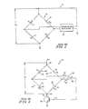
- the circuit is constructed from a wheatstone bridge 10 and a high gain differential amplifier 12.
- the amplifier 12 converts the voltage difference at its inputs to an output current to the bridge 10.
- the wheatstone bridge is made up of four resistors 14, 15, 16 and 17 having resistances, R,, R z , R2 and R4, respectively.
- Resistor 14 comprises a foil and will be referred to as foil 14.
- Resistors 15, 16 and 17 can be considered, for now, as standard resistors of constant value.
- resistors 15 and 16 that form the right, or reference, side of the bridge have much larger resistances than the resistors 14 and 17 on the left, or sensing, side. This limits the amount of current which flows through the right side of the bridge. Resistors 15 and 16 are equal in value.
- the bridge With the resistances R : and R3 equal, the bridge is balanced when R, and R 4 are equal.
- the resistance R, of foil 14 varies with its temperature. Therefore, the bridge is balanced when the temperature of foil 14 is such that its resistance R, is equal to R 4 .
- the foil 14 temperature at which the bridge balances is fixed by choice of R 2 , R3 and R 4 .
- the cooling due to the air flow will also increase, and the temperature of foil 14 will start to drop.
- the lower temperature of foil 14 produces a lower foil resistance R,, causing the bridge 10 to become more unbalanced.
- the difference voltage input to the amplifier 12 then increases, and the current flowing through the foil 14 increases, resulting in sufficient electrical heating to offset the increased cooling and return the bridge 10 to balance.
- An output signal from the mass air flow rate sensor 8 is obtained from the current flowing through the foil 14 which is related to the mass flow rate of air flowing across the foil 14. This current, multiplied by the resistance in the left leg of the bridge, (R, + R 4 ), yields the bridge voltage V b .
- Resistance R4 is constant and the resistance of the foil 14, R,, remains essentially constant throughout the mass air flow rate operating range as it is determined by the requirements of bridge balance.
- the bridge voltage V b varies only with the current flowing through the foil 14 and is therefore suitable as the output of the mass air flow rate sensor 8.
- the bridge voltage V b may be transformed into an AC signal which is must less sensitive to electrical noise.
- a quantitative steady state model of the mass air flow rate sensor is developed to provide further insight into its operation.
- the model will help to illustrate more completely how the mass air flow sensor works, and how various outside factors such as variations in ambient air temperature affect the operation of the device.
- a heat transfer model is needed to predict the heat transfer Q
- a model of the electrical circuit is needed to predict the foil 14 current I" and with it the bridge output voltage, V b .
- the first step in development of the steady state model is to find the relation between the mass flow rate ⁇ , and the heat transfer Q.
- the heat transfer out of the foil 14 is assumed to be composed of convective and radiative heat transfer. Each of these is discussed individually.
- the convective heat transfer is the heat transfer that occurs as a direct result of air flowing over the foil 14.
- the foil 14 is modeled as a flat plate of uniform temperature in parallel flow.
- the general expression for convective transfer out of the plate can be written as where
- the total heat transfer is the sum of the convective and radiative heat transfer.
- Equation 6 provides a model of the heat transfer process affecting the foil 14. Through use of the model, it can be shown that convection is the dominant mode of heat transfer.
- Fig. 2 illustrates schematically a simplified circuit for a prior art bridge type mass air flow rate sensor 18.
- the mass air flow rate sensor 18 has a bridge circuit 19.
- Bridge circuit 19 illustratively comprises first and second series connected legs 20, 22 which are connected in parallel with third and fourth series connected legs 24, 26.
- First leg 20 illustratively comprises a metal foil element 28 which has a resistance R,.
- Second, third and fourth legs 22, 24, 26, respectively illustratively comprise resistors 25, 21, 23, respectively, which have resistances of R 4 , R 2 , and R 3 , respectively.
- the resistances of bridge circuit 19 are given the same designations, R,, R 2 , R 3 , R 4 , as the resistances of bridge circuit 10 in Fig. 1.
- a junction of legs 24, 26 is connected to the + input terminal 30 of a differential amplifier 32.
- a junction of legs 20, 22 is connected to the - input terminal 34 of differential amplifier 32.
- An output terminal 36 of differential amplifier 32 is connected to the base of a transistor 38.
- the emitter of transistor 38 is connected to ground and the collector of transistor 38 is connected to the junction 40 of legs 22, 26 of bridge circuit 19.
- the junction 42 of legs 20, 24 of bridge circuit 19 is connected to the positive terminal B + of a source of electrical power, not shown.
- the simple electrical circuit shown in Fig. 2 is used to develop the relationships between the resistance R, of the foil 28, the voltage V b of the bridge 19 and the current I 1 flowing through the foil 28.
- the following variables are defined: R, Resistance of the foil 28; T, Temperature of the foil 28; I, Current flowing through the foil 28;
- resistances R 2 , R 3 , R 4 of resistors 21, 23, 25, respectively, are all assumed to be constant at this point.
- the equations which characterize the operation of the circuit shown in Fig. 2 are now found.
- the voltage e- is equal to the voltage v c plus the voltage drop across R 4 .
- the voltage drop across R 4 can be found from a voltage division of V b .
- the voltage e- can thus be written as Similarly, the voltage e + is
- Equation 9 may be solved for the bridge output voltage to give
- Equation 10 provides the desired relation between the bridge voltage V b and the foil resistance R,.
- the current flowing through the foil 28 must be found.
- the current I may be obtained from the bridge voltage V b and the resistances R, and R4
- the voltage to frequency converter is a voltage controlled oscillator (vco) and its linear input-output relation is given below.
- Equations 2, 6, 10, 11, 12 and 13 The six equations which describe the model, Equations 2, 6, 10, 11, 12 and 13 are renumbered and listed below
- Equation 18 gives V b as a function of v B (the voltage at the base of the transistor with respect to ground), A (the op-amp gain) and the four resistances that form the bridge. Of these, R 2 , R,, R4, A and v B have been assumed constant, leaving R, as unknown.
- Equation 20 yields the bridge balance equation.
- the steady state foil resistance R is fixed by the resistances R 2 , R 3 , R 4 .
- the temperature of the foil 28, T is also fixed by Equation 14.
- R 2 , R 3 , and R. the temperature at which the foil 28 will operate, i.e., the temperature of the foil 28 at which it has a resistance which balances the bridge 19, can be selected.
- Equation 15 gives the total heat transfer out of the foil 28, Q, as a function of the mass flow rate, ⁇ . If the total heat transfer is known as a function of the mass flow rate, then the energy balance, Equation 16, can be used, along with the foil resistance R,, to calculate the current I, flowing through the foil 28. Combining Equations 17 and 22 provides the bridge voltage
- Equations 14-19 a simultaneous solution of the six system equations, Equations 14-19, is required.
- the equations are solved by an iterative procedure.
- the solution procedure provides the output voltage and frequency of the mass air flow rate sensor 18 for a given mass flow rate, assuming that the ambient air temperature and the mass air flow rate sensor 18 flow tube temperature are known.
- circuit model required specification of the parameters of bridge circuit 19.
- the values chosen are representative of actual values used in a mass air flow rate sensor 18.
- the resistances R2 and R 3 of resistors 21 and 23 were chosen as 1352.73 and 1417.91 ohms, respectively.
- the resistance R 4 of resistor 25 was specified as 5.0281 ohms, and the foil 28 had a resistance of 4.797 ohms at a temperature of 95 degrees centigrade.
- the gain, A, of the op-amp 32 was 100,000. Due to the requirements of bridge balance, the bridge operates with the foil 28 at a temperature of approximately 95 degrees centigrade.
- the operating range of the mass air flow rate sensor was assumed to be from 2 g/s to 140 g/s.
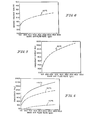
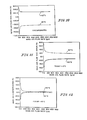
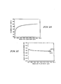
- the model of the mass air flow rate sensor was used to predict the output voltage over this flow range while holding the ambient air temperature at a constant 20 degrees centigrade. The result is shown in Fig. 4.
- the bridge voltage is converted to a frequency to minimize noise corruption of the signal.
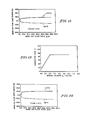
- the output frequency is shown in Fig. 5.
- the mass air flow rate sensor must measure mass air flows which range in temperature from -40°C to 80°C.
- mass air flows which range in temperature from -40°C to 80°C.
- Fig. 5 a plot of the frequency output of the mass air flow rate sensor 18 against mass air flow rate was presented in Fig. 5.
- the ambient air temperature was 20°C.
- Results from the same simulation at ambient air temperatures at -40°C, 20°C and 80°C are shown in Fig. 6.
- the temperature T does not vary as the ambient air temperature varies.
- the dependence of the output frequency on ambient air temperature may then be explained by examination of the simple heat transfer model written below.
- the convective heat transfer is a function of the foil temperature minus the ambient air temperature.
- the heat loss by radiation is a function of the temperature of foil 28 raised to the fourth power minus the surface temperature of the flow tube (100 in Fig. 18; 200 in Fig. 22) raised to the fourth power.
- the flow tube temperature is related to the ambient air temperature.
- the dominant heat transfer mode is convection. It would appear by looking at the heat transfer model (Equation 24) that maintaining a fixed temperature difference between the foil 28 and the air would eliminate the effect of ambient air temperature variation on the convective heat transfer.
- the radiative heat transfer depends upon the difference between the fourth powers of the foil and flow tube temperatures, where the flow tube temperature is dependent upon the ambient air temperature.
- fixing the temperature difference between the foil 28 and ambient air temperatures does not render the radiative term independent of ambient temperature variations. Rather, with respect to some reference ambient temperature, it produces a radiative heat transfer in excess of the original for increases in the ambient temperature and less than the original for decreases in the ambient temperature.
- the convective and radiative heat transfer terms still depend upon ambient temperature. As the ambient air temperature increases, both forms -of heat transfer become more efficient, and the total heat transfer increases. The converse is true at low ambient temperatures.
- the terms low and high ambient temperatures are with respect to a reference ambient temperature of 20°C.
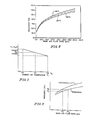
- Fig. 7 provides a plot of the difference between the temperatures of foil 28 and ambient air temperatures to be employed.
- the maximum amount of adjustment from a constant temperature difference is termed TCOMP, and the variation of the temperature difference with ambient temperature is linear.
- This type of foil 28 temperature function is achieved by allowing the resistance R2of resistor 21 to vary with ambient air temperature. Since the resistance of the foil 28 in steady state operation is determined by the values of the other bridge resistors 21, 23, 25, changing the resistance R2of resistor 21 changes the foil resistance R, at which the bridge circuit 19 balances, and thus changes the operating temperature of the foil 28.
- the resistance R 2 is provided by two resistors.
- the first resistor is required to vary with ambient temperature.
- the second resistor is to remain constant as ambient temperature changes. While it might appear desirable to specify R 2 as a single temperature-dependent resistor, such a configuration would force a specified functional relation between resistance and temperature which would be a difficult constraint to satisfy when producing the device.
- the leg 24 of the bridge circuit 19 that contains these two resistors has a very high resistance relative to leg 20, and thus carries very little current. Therefore, the variable resistor will have a very small self-heating effect, and if placed in the air flow, it will have a temperature very near that of the air flowing through the tube.
- the frequency output of the mass air flow rate sensor 18 will vary with ambient temperature.
- the frequency output of the mass air flow rate sensor 18 can also be affected by installation, aging, manufacturing tolerances and other factors.
- a way of relating a change in frequency output to indicated mass air flow rate error is needed. To begin. the mass air flow rate error is defined as where 0
- FIG. 9 A representation of the standard output curve of a mass air flow rate sensor and a different curve which is the output curve for an individual mass air flow rate sensor are illustrated in Fig. 9.
- the individual mass air flow rate sensor will provide a different output frequency than the standard mass air flow rate sensor when subjected to a flow rate of ⁇ 1 .
- the frequency output of the device would be f 2 using the individual curve shown in Fig. 9.
- the frequency f 2 implies that a mass flow rate of ⁇ is being input, rather than the true flow rate of ⁇ 1 .
- Equation 27 can be used to determine the error caused by a change in ambient air temperature.
- the quantities needed for the calculation consist of f, and f 2 , the slope of the standard curve at the calculation point, and the mass flow rate.
- the simulation is used to calculate the frequency f, that occurs at the mass flow rate of ⁇ , at the standard ambient temperature, as well as the slope of the standard curve at this mass air flow rate.
- the frequency f 2 that results from the mass flow rate m , at the new ambient temperature is also calculated from the simulation. All of the needed quantities are now known and the mass air flow rate error due to the ambient temperature change may be calculated using Equation 27.
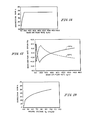
- the indicated mass flow error of the uncompensated mass air flow rate sensor (R 2* R 2 (T a )) is shown in Fig. 10.
- the two curves represent the error at the temperature extremes of -40° and 80°C.
- the indicated mass air flow rate error of the compensated mass air flow rate sensor with TCOMP 0°C is presented in Fig. 11. Comparison of the two figures readily shows the reduction in error achieved by the TCOMP compensation.
- TCOMP 13°C
- TCOMP 11°C.
- Equation 21 To generate V c , let The bridge balance relation of Equation 21 is repeated below for convenience.
- Equation 30 yields V c > 0.
- V c One further refinement is required in the development of V c .
- the design and procurement processes will cause resistances R, and R4 to be unequal at the ambient air reference temperature T ar , contrary to the assumption made above. If this is the case, then at the ambient air reference temperature, V will not be equal to 0 as required.
- Equation 37 One simple and reasonable choice for k is to use that value at each ⁇ which is the average of the values required to null the errors at the extreme temperatures, i.e. Implementation of the correction gain as determined directly from Equation 37 is certainly possible and will be discussed in the section on digital implementation.
- Equation 37 provides a guide to the selection of the correction gain for analog implementation. Since the correction gain is to vary with ⁇ , let k( ⁇ ) be represented as a function of the bridge voltage V b which, of course, does vary with ⁇ . Indeed, for ease of implementation, assume that a simple linear relationship will suffice.
- the linear variation of k with V b with k ranging from .07 to .45, occurs as the mass flow rate varies from 2 to 15 grams/sec, after which the gain is held constant.
- the variation of k with V b is shown in Fig. 15.
- the corresponding variation of k with ⁇ is shown in Fig. 16.
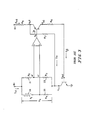
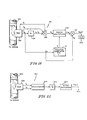
- Fig. 18 is a block diagram of an analog system implementing the correction scheme of this invention.
- An error correcting mass air flow rate sensor 101 includes a mass air flow rate sensor 102 with TCOMP temperature compensation.
- Input signals to mass air flow rate sensor 102 are ambient temperature T a and mass air flow rate ⁇ .
- the output signals from mass air flow rate sensor 102, V b , V, and V4 comprise the bridge voltage, V b , the voltage across R, and the voltage across R 4 , respectively.
- the bridge voltage V b is amplified by a constant gain amplifier 104 having a gain of k z to generate the correction voltage offset given by k z V b in Equation 36.
- the resulting signal, k z V b is then summed with V 1 and -V 4 by a voltage summer 106 to generate the correction voltage V c given by Equation 36.
- the bridge voltage V b also comprises an input signal to a function generator 110 which determines k as a function of V b .
- An output signal from function generator 110 is coupled to an analog multiplier 108.
- Analog multiplier 108 multiplies the correction voltage V c by k to generate the correction kV c to the bridge voltage V b as required by Equation 29.
- a voltage summer 112 sums the bridge voltage V b with the correction voltage k V c to generate the corrected bridge voltage V out .
- This V out value is then provided to an engine control unit (not shown) which uses V out in an engine control strategy. Since such an engine control unit typically is digital, e.g., a microprocessor, an A/D converter may be inserted between the summer 112 and the engine control unit.
- the correction scheme of this invention can also be implemented digitally. As in the previous section, the correction voltage of Equation 36, repeated below for convenience, and the corrected bridge output voltage of Equation 29, also repeated here are used. The significant difference is that since the gain will be set digitally, it may be controlled much more precisely than in the analog implementation scheme.
- Equation 37 For comparison purposes, take as the correction gain that gain given by Equation 37. That is, as before, the average of the correct values at the two extreme temperatures is used as the gain, Specifically, assume that the gain specified by Equation 42 has been determined at each of 15 standard flow points that span the flow range of interest. In this illustration, ⁇ ranges from 2 to 140 grams/sec.
- V bref (i) there is a reference bridge voltage value V bref (i) and a corresponding correction gain k(i).
- the components to implement the correction scheme of this invention digitally are:
- FIG. 22 is a block diagram of a digital system for implementing the correction scheme of this invention.
- An error correcting mass air flow rate sensor 201 includes a mass air flow rate sensor 202 with TCOMP temperature compensation.
- the input signals to mass air flow rate sensor 202 are ambient temperature T a and mass air flow rate ⁇ .
- the output signals, V, and V 4 , from mass air flow sensor 202 comprise the voltages across R, and R., respectively.
- V, and V4 are both coupled to multiplexer 204 which alternately provides V, and V 4 as inputs to analog-to-ditial converter (A/D) 206.
- A/D 206 digitizes the V 1 and V 4 signals and provides the digital values to microprocessor 208.
- Microprocessor 208 includes a program which uses Equation 43 to provide a correction gain k, uses Equation 40 to provide the voltage correction V c and then uses Equation 41 to determine the corrected bridge output voltage value V out in the manner described above. This V out value is then provided to an engine control unit (not shown) which uses V out in an engine control strategy.
Landscapes
- Physics & Mathematics (AREA)
- Fluid Mechanics (AREA)
- General Physics & Mathematics (AREA)
- Measuring Volume Flow (AREA)
- Details Of Flowmeters (AREA)
- Measuring Instrument Details And Bridges, And Automatic Balancing Devices (AREA)
Applications Claiming Priority (2)
| Application Number | Priority Date | Filing Date | Title |
|---|---|---|---|
| US06/850,511 US4807151A (en) | 1986-04-11 | 1986-04-11 | Electrical technique for correcting bridge type mass air flow rate sensor errors resulting from ambient temperature variations |
| US850511 | 1986-04-11 |
Publications (2)
| Publication Number | Publication Date |
|---|---|
| EP0240637A1 true EP0240637A1 (de) | 1987-10-14 |
| EP0240637B1 EP0240637B1 (de) | 1992-09-23 |
Family
ID=25308337
Family Applications (1)
| Application Number | Title | Priority Date | Filing Date |
|---|---|---|---|
| EP86309547A Expired EP0240637B1 (de) | 1986-04-11 | 1986-12-08 | Elektrische Methode zum Korrigieren von Fehlern, die bei Luftmassendurchflusssensoren vom Brückentyp auftreten und von Schwankungen der Umgebungstemperatur herrühren |
Country Status (4)
| Country | Link |
|---|---|
| US (1) | US4807151A (de) |
| EP (1) | EP0240637B1 (de) |
| JP (1) | JPS62245924A (de) |
| DE (1) | DE3686818D1 (de) |
Cited By (4)
| Publication number | Priority date | Publication date | Assignee | Title |
|---|---|---|---|---|
| EP0890827A1 (de) | 1997-07-08 | 1999-01-13 | Hitachi, Ltd. | Thermische Vorrichtung zum Messen der Strömung und Temperaturfehlerkorrekturgerät dafür |
| EP1439378A3 (de) * | 2003-01-14 | 2005-12-28 | Hitachi, Ltd. | Heissdrahtdurchflussmesser mit linearem Frequenzausgang |
| DE4324040B4 (de) * | 1992-07-21 | 2009-09-17 | Robert Bosch Gmbh | Massenstromsensor |
| EP2068128B1 (de) * | 2007-05-25 | 2018-11-14 | Hitachi, Ltd. | Thermischer Durchflussmesser für Motorkontrollsystem |
Families Citing this family (72)
| Publication number | Priority date | Publication date | Assignee | Title |
|---|---|---|---|---|
| US4974563A (en) * | 1988-05-23 | 1990-12-04 | Toyota Jidosha Kabushiki Kaisha | Apparatus for estimating intake air amount |
| JP2717665B2 (ja) * | 1988-05-31 | 1998-02-18 | 株式会社豊田中央研究所 | 内燃機関の燃焼予測判別装置 |
| JPH01315643A (ja) * | 1988-06-15 | 1989-12-20 | Mitsubishi Electric Corp | エンジンの燃料制御装置 |
| US4956793A (en) * | 1988-06-24 | 1990-09-11 | Honeywell Inc. | Method and apparatus for measuring the density of fluids |
| DE3841637C1 (de) * | 1988-12-10 | 1990-05-10 | Gebr. Schmidt Fabrik Fuer Feinmechanik, 7742 St Georgen, De | |
| KR930004080B1 (ko) * | 1989-02-14 | 1993-05-20 | 미쯔비시 덴끼 가부시끼가이샤 | 열식 유량 감지기의 신호 처리방법 |
| JPH02308950A (ja) * | 1989-05-25 | 1990-12-21 | Japan Electron Control Syst Co Ltd | 内燃機関の制御装置における空気漏れ自己診断装置及び空気漏れ学習補正装置 |
| JPH0760107B2 (ja) * | 1989-07-11 | 1995-06-28 | 三菱電機株式会社 | 熱式流量センサの信号処理方法 |
| US5237523A (en) * | 1990-07-25 | 1993-08-17 | Honeywell Inc. | Flowmeter fluid composition and temperature correction |
| JPH04311643A (ja) * | 1991-04-10 | 1992-11-04 | Hitachi Ltd | エンジンの気筒流入空気量算出方法 |
| DE4120388C2 (de) * | 1991-06-19 | 2001-05-03 | Bosch Gmbh Robert | Verfahren zur Temperaturerfassung |
| US5259424A (en) * | 1991-06-27 | 1993-11-09 | Dvco, Inc. | Method and apparatus for dispensing natural gas |
| US5263369A (en) * | 1992-07-24 | 1993-11-23 | Bear Medical Systems, Inc. | Flow sensor system and method |
| US5383357A (en) * | 1993-12-20 | 1995-01-24 | Doll; John A. | Mass air flow sensor device |
| DE19580750C2 (de) * | 1994-06-13 | 2002-07-25 | Hitachi Ltd | Luftströmungsraten-Messvorrichtung |
| US5460039A (en) * | 1994-07-12 | 1995-10-24 | Bear Medical Systems, Inc. | Flow sensor system |
| DE4432714C1 (de) * | 1994-09-14 | 1995-11-02 | Deutsche Forsch Luft Raumfahrt | Verfahren zur Größenbestimmung luftgetragener Wassertropfen |
| DE19501347C2 (de) * | 1995-01-18 | 1996-12-19 | Draegerwerk Ag | Vorrichtung zur Messung des Durchflusses in einem Fluidkanal |
| US5585553A (en) * | 1995-07-28 | 1996-12-17 | Caterpillar Inc. | Apparatus and method for diagnosing an engine using a boost pressure model |
| US7254518B2 (en) * | 1996-03-28 | 2007-08-07 | Rosemount Inc. | Pressure transmitter with diagnostics |
| US7630861B2 (en) * | 1996-03-28 | 2009-12-08 | Rosemount Inc. | Dedicated process diagnostic device |
| US6907383B2 (en) | 1996-03-28 | 2005-06-14 | Rosemount Inc. | Flow diagnostic system |
| US8290721B2 (en) * | 1996-03-28 | 2012-10-16 | Rosemount Inc. | Flow measurement diagnostics |
| US7623932B2 (en) | 1996-03-28 | 2009-11-24 | Fisher-Rosemount Systems, Inc. | Rule set for root cause diagnostics |
| US7949495B2 (en) * | 1996-03-28 | 2011-05-24 | Rosemount, Inc. | Process variable transmitter with diagnostics |
| US7085610B2 (en) | 1996-03-28 | 2006-08-01 | Fisher-Rosemount Systems, Inc. | Root cause diagnostics |
| US5654507A (en) * | 1996-07-03 | 1997-08-05 | Board Of Trustees Operating Michigan State University | Pulse width modulated constant temperature anemometer |
| US6434504B1 (en) * | 1996-11-07 | 2002-08-13 | Rosemount Inc. | Resistance based process control device diagnostics |
| US6220747B1 (en) * | 1997-08-14 | 2001-04-24 | Michael Gosselin | Proportional pump system for viscous fluids |
| US6611775B1 (en) | 1998-12-10 | 2003-08-26 | Rosemount Inc. | Electrode leakage diagnostics in a magnetic flow meter |
| US6615149B1 (en) | 1998-12-10 | 2003-09-02 | Rosemount Inc. | Spectral diagnostics in a magnetic flow meter |
| US7010459B2 (en) * | 1999-06-25 | 2006-03-07 | Rosemount Inc. | Process device diagnostics using process variable sensor signal |
| AU5780300A (en) | 1999-07-01 | 2001-01-22 | Rosemount Inc. | Low power two-wire self validating temperature transmitter |
| US6556145B1 (en) | 1999-09-24 | 2003-04-29 | Rosemount Inc. | Two-wire fluid temperature transmitter with thermocouple diagnostics |
| US6470741B1 (en) * | 2000-06-23 | 2002-10-29 | Instrumentarium, Inc. | Hot wire anemometer gas flow sensor having improved operation and compensation |
| US6970003B2 (en) | 2001-03-05 | 2005-11-29 | Rosemount Inc. | Electronics board life prediction of microprocessor-based transmitters |
| US6629059B2 (en) | 2001-05-14 | 2003-09-30 | Fisher-Rosemount Systems, Inc. | Hand held diagnostic and communication device with automatic bus detection |
| US6859755B2 (en) | 2001-05-14 | 2005-02-22 | Rosemount Inc. | Diagnostics for industrial process control and measurement systems |
| US6772036B2 (en) | 2001-08-30 | 2004-08-03 | Fisher-Rosemount Systems, Inc. | Control system using process model |
| US6813570B2 (en) * | 2002-05-13 | 2004-11-02 | Delphi Technologies, Inc. | Optimized convection based mass airflow sensor circuit |
| EP1646864B1 (de) * | 2003-07-18 | 2018-11-07 | Rosemount Inc. | Prozessdiagnostik |
| US7018800B2 (en) * | 2003-08-07 | 2006-03-28 | Rosemount Inc. | Process device with quiescent current diagnostics |
| US7627441B2 (en) * | 2003-09-30 | 2009-12-01 | Rosemount Inc. | Process device with vibration based diagnostics |
| US7523667B2 (en) * | 2003-12-23 | 2009-04-28 | Rosemount Inc. | Diagnostics of impulse piping in an industrial process |
| US7054767B2 (en) * | 2004-02-12 | 2006-05-30 | Eldridge Products, Inc. | Thermal mass flowmeter apparatus and method with temperature correction |
| US6920799B1 (en) | 2004-04-15 | 2005-07-26 | Rosemount Inc. | Magnetic flow meter with reference electrode |
| US7046180B2 (en) | 2004-04-21 | 2006-05-16 | Rosemount Inc. | Analog-to-digital converter with range error detection |
| US7205781B2 (en) * | 2005-01-12 | 2007-04-17 | Visteon Global Technologies, Inc. | Mass air flow circuit having pulse width modulation feedback control |
| JP2006258676A (ja) * | 2005-03-18 | 2006-09-28 | Hitachi Ltd | 熱式流量計 |
| US8112565B2 (en) * | 2005-06-08 | 2012-02-07 | Fisher-Rosemount Systems, Inc. | Multi-protocol field device interface with automatic bus detection |
| US20070068225A1 (en) * | 2005-09-29 | 2007-03-29 | Brown Gregory C | Leak detector for process valve |
| US7653503B2 (en) * | 2006-04-20 | 2010-01-26 | Tao Of Systems Integration, Inc. | Temperature-compensating sensor system |
| US7953501B2 (en) | 2006-09-25 | 2011-05-31 | Fisher-Rosemount Systems, Inc. | Industrial process control loop monitor |
| EP2074385B2 (de) | 2006-09-29 | 2022-07-06 | Rosemount Inc. | Magnetischer flussmesser mit verifikationsfunktion |
| US7321846B1 (en) | 2006-10-05 | 2008-01-22 | Rosemount Inc. | Two-wire process control loop diagnostics |
| US7775091B2 (en) * | 2007-04-17 | 2010-08-17 | Gm Global Technology Operations, Inc. | Method and apparatus for determining intake air mass |
| JP4467603B2 (ja) * | 2007-05-29 | 2010-05-26 | 日立オートモティブシステムズ株式会社 | ガス流量計及び内燃機関制御システム |
| US8898036B2 (en) * | 2007-08-06 | 2014-11-25 | Rosemount Inc. | Process variable transmitter with acceleration sensor |
| US7590511B2 (en) * | 2007-09-25 | 2009-09-15 | Rosemount Inc. | Field device for digital process control loop diagnostics |
| US8197133B2 (en) * | 2008-02-22 | 2012-06-12 | Brooks Instruments, Llc | System and method for sensor thermal drift offset compensation |
| JP4993311B2 (ja) | 2008-05-30 | 2012-08-08 | 株式会社デンソー | 空気流量測定装置、空気流量補正方法、および、プログラム |
| US7921734B2 (en) * | 2009-05-12 | 2011-04-12 | Rosemount Inc. | System to detect poor process ground connections |
| US8201442B2 (en) * | 2009-09-25 | 2012-06-19 | Cummins Inc. | System and method for estimating EGR mass flow rates |
| US9207670B2 (en) | 2011-03-21 | 2015-12-08 | Rosemount Inc. | Degrading sensor detection implemented within a transmitter |
| GB2499577A (en) * | 2011-11-29 | 2013-08-28 | Eaton Aerospace Ltd | Aircraft on board inert gas generation system |
| DE102011088902A1 (de) * | 2011-12-16 | 2013-06-20 | Continental Automotive Gmbh | Sensor zur Erfassung des Massenstroms und der Temperatur eines Fluidstromes |
| US9052240B2 (en) | 2012-06-29 | 2015-06-09 | Rosemount Inc. | Industrial process temperature transmitter with sensor stress diagnostics |
| US9602122B2 (en) | 2012-09-28 | 2017-03-21 | Rosemount Inc. | Process variable measurement noise diagnostic |
| EP2899519B1 (de) * | 2014-01-24 | 2016-11-16 | Siemens Schweiz AG | Temperaturmessvorrichtung |
| US10436157B2 (en) * | 2017-11-09 | 2019-10-08 | Quirt Evan Crawford | Apparatus for improving engine performance |
| US10761153B2 (en) * | 2018-05-07 | 2020-09-01 | Infineon Technologies Ag | Magnetic sensor with an asymmetric wheatstone bridge |
| CN115542717A (zh) * | 2022-06-29 | 2022-12-30 | 浙江中控技术股份有限公司 | 回路平衡pid控制方法、装置、电子装置和存储介质 |
Citations (4)
| Publication number | Priority date | Publication date | Assignee | Title |
|---|---|---|---|---|
| DE2350083A1 (de) * | 1972-10-09 | 1974-04-18 | Yamatake Honeywell Co Ltd | Schaltungsanordnung zum korrigieren des ausgangssignals einer messvorrichtung |
| DE3106508A1 (de) * | 1981-02-21 | 1982-09-09 | Robert Bosch Gmbh, 7000 Stuttgart | Luftmassenmesseinrichtung bei einer brennkraftmaschine |
| DE3424642A1 (de) * | 1983-07-11 | 1985-01-31 | General Motors Corp., Detroit, Mich. | Festkoerper-luftstroemungsfuehler |
| DE3516757A1 (de) * | 1984-05-09 | 1985-11-14 | Nippon Soken, Inc., Nishio, Aichi | Direkt beheizte gasstroemungsmessvorrichtung |
Family Cites Families (14)
| Publication number | Priority date | Publication date | Assignee | Title |
|---|---|---|---|---|
| US31906A (en) * | 1861-04-02 | Improvement in varnishing photographs on paper | ||
| US4102199A (en) * | 1976-08-26 | 1978-07-25 | Megasystems, Inc. | RTD measurement system |
| US4057755A (en) * | 1976-09-10 | 1977-11-08 | Bodenseewerk Perkin-Elmer & Co., Gmbh | Thermal conductivity detector circuit |
| US4063447A (en) * | 1977-03-14 | 1977-12-20 | Honeywell, Inc. | Bridge circuit with drift compensation |
| JPS53131326A (en) | 1977-04-22 | 1978-11-16 | Hitachi Ltd | Control device of internal combustn engine |
| JPS5453877A (en) * | 1977-10-07 | 1979-04-27 | Hitachi Ltd | Temperature compensation circuit of semiconductor strain gauge |
| US4192005A (en) * | 1977-11-21 | 1980-03-04 | Kulite Semiconductor Products, Inc. | Compensated pressure transducer employing digital processing techniques |
| JPS5618721A (en) * | 1979-07-24 | 1981-02-21 | Hitachi Ltd | Air flow meter |
| US4399515A (en) * | 1981-03-31 | 1983-08-16 | The United States Of America As Represented By The Administrator Of The National Aeronautics And Space Administration | Self-correcting electronically scanned pressure sensor |
| JPS58114199A (ja) * | 1981-12-26 | 1983-07-07 | 株式会社東芝 | 2線式圧力差圧伝送器 |
| JPH0613859B2 (ja) * | 1983-03-24 | 1994-02-23 | 日本電装株式会社 | 内燃機関の制御装置 |
| EP0144027B1 (de) * | 1983-11-16 | 1990-06-20 | Nippondenso Co., Ltd. | Gerät zum Messen der Ansaugluftdurchflussquote für einen Motor |
| JPS60195342A (ja) * | 1984-03-19 | 1985-10-03 | Hitachi Ltd | エンジン制御装置 |
| JPH0625560B2 (ja) * | 1985-06-17 | 1994-04-06 | 日本電装株式会社 | エンジンの制御装置 |
-
1986
- 1986-04-11 US US06/850,511 patent/US4807151A/en not_active Expired - Fee Related
- 1986-11-25 JP JP61280538A patent/JPS62245924A/ja active Pending
- 1986-12-08 DE DE8686309547T patent/DE3686818D1/de not_active Expired - Lifetime
- 1986-12-08 EP EP86309547A patent/EP0240637B1/de not_active Expired
Patent Citations (4)
| Publication number | Priority date | Publication date | Assignee | Title |
|---|---|---|---|---|
| DE2350083A1 (de) * | 1972-10-09 | 1974-04-18 | Yamatake Honeywell Co Ltd | Schaltungsanordnung zum korrigieren des ausgangssignals einer messvorrichtung |
| DE3106508A1 (de) * | 1981-02-21 | 1982-09-09 | Robert Bosch Gmbh, 7000 Stuttgart | Luftmassenmesseinrichtung bei einer brennkraftmaschine |
| DE3424642A1 (de) * | 1983-07-11 | 1985-01-31 | General Motors Corp., Detroit, Mich. | Festkoerper-luftstroemungsfuehler |
| DE3516757A1 (de) * | 1984-05-09 | 1985-11-14 | Nippon Soken, Inc., Nishio, Aichi | Direkt beheizte gasstroemungsmessvorrichtung |
Cited By (8)
| Publication number | Priority date | Publication date | Assignee | Title |
|---|---|---|---|---|
| DE4324040B4 (de) * | 1992-07-21 | 2009-09-17 | Robert Bosch Gmbh | Massenstromsensor |
| EP0890827A1 (de) | 1997-07-08 | 1999-01-13 | Hitachi, Ltd. | Thermische Vorrichtung zum Messen der Strömung und Temperaturfehlerkorrekturgerät dafür |
| US6230559B1 (en) | 1997-07-08 | 2001-05-15 | Hitachi, Ltd. | Thermal type flow measuring instrument and temperature-error correcting apparatus thereof |
| KR100491488B1 (ko) * | 1997-07-08 | 2005-09-02 | 가부시키 가이샤 히다치 카 엔지니어링 | 열형유량측정장치및그온도오차보정수단 |
| EP1793209A1 (de) * | 1997-07-08 | 2007-06-06 | Hitachi, Ltd. | Thermal-Durchflussmessgerät und Temperaturfehlerkorrekturvorrichtung daraus |
| EP1439378A3 (de) * | 2003-01-14 | 2005-12-28 | Hitachi, Ltd. | Heissdrahtdurchflussmesser mit linearem Frequenzausgang |
| US7140246B2 (en) | 2003-01-14 | 2006-11-28 | Hitachi, Ltd. | Frequency output type hot-wire flow meter |
| EP2068128B1 (de) * | 2007-05-25 | 2018-11-14 | Hitachi, Ltd. | Thermischer Durchflussmesser für Motorkontrollsystem |
Also Published As
| Publication number | Publication date |
|---|---|
| DE3686818D1 (de) | 1992-10-29 |
| US4807151A (en) | 1989-02-21 |
| JPS62245924A (ja) | 1987-10-27 |
| EP0240637B1 (de) | 1992-09-23 |
Similar Documents
| Publication | Publication Date | Title |
|---|---|---|
| EP0240637A1 (de) | Elektrische Methode zum Korrigieren von Fehlern, die bei Luftmassendurchflusssensoren vom Brückentyp auftreten und von Schwankungen der Umgebungstemperatur herrühren | |
| EP0724151A1 (de) | Gerät zur Messung der Wärmeleitfähigkeit | |
| JP3891600B2 (ja) | 空気圧マニホルドの温度及び圧力の補償方法及び装置 | |
| EP0878707A1 (de) | Sensor mit heizung | |
| JPH0349374B2 (de) | ||
| JP2003240620A (ja) | 気体流量測定装置 | |
| US4872339A (en) | Mass flow meter | |
| US20210389193A1 (en) | Flexible Bridge Sensor Electronic Architecture and Method for Implementing Same | |
| US5107812A (en) | Thermal type intake air flow measuring instrument and internal combustion engine control apparatus using this measuring instrument | |
| US6813570B2 (en) | Optimized convection based mass airflow sensor circuit | |
| KR20020081398A (ko) | 열식 공기유량계 | |
| GB2201791A (en) | Transducer signal conditioner | |
| US6094982A (en) | Flow measuring device and flow measuring method | |
| KR100398492B1 (ko) | 공기유량계및공기유량검출방법 | |
| US7331237B2 (en) | Technique for improving Pirani gauge temperature compensation over its full pressure range | |
| US4854167A (en) | Mass fluid flow sensor | |
| US4672847A (en) | Hot-wire flow rate measuring apparatus | |
| US4845984A (en) | Temperature compensation for a thermal mass flow meter | |
| US6230559B1 (en) | Thermal type flow measuring instrument and temperature-error correcting apparatus thereof | |
| JPH075008A (ja) | 空気流なくして質量空気流センサの時間応答を較正する方法 | |
| US5656938A (en) | Temperature compensation in mass flow sensors employing the hot-wire anemometer principle | |
| US4637251A (en) | Symmetrical bridge circuit for measuring mass air flow | |
| CN1107221C (zh) | 确定流动介质通过能力的装置 | |
| JPH03172717A (ja) | 流量計 | |
| JP3105609B2 (ja) | 発熱抵抗体式空気流量計 |
Legal Events
| Date | Code | Title | Description |
|---|---|---|---|
| PUAI | Public reference made under article 153(3) epc to a published international application that has entered the european phase |
Free format text: ORIGINAL CODE: 0009012 |
|
| AK | Designated contracting states |
Kind code of ref document: A1 Designated state(s): AT BE CH DE ES FR GB GR IT LI LU NL SE |
|
| 17P | Request for examination filed |
Effective date: 19871121 |
|
| RBV | Designated contracting states (corrected) |
Designated state(s): DE FR GB IT SE |
|
| 17Q | First examination report despatched |
Effective date: 19891121 |
|
| GRAA | (expected) grant |
Free format text: ORIGINAL CODE: 0009210 |
|
| AK | Designated contracting states |
Kind code of ref document: B1 Designated state(s): DE FR GB IT SE |
|
| PG25 | Lapsed in a contracting state [announced via postgrant information from national office to epo] |
Ref country code: IT Free format text: LAPSE BECAUSE OF FAILURE TO SUBMIT A TRANSLATION OF THE DESCRIPTION OR TO PAY THE FEE WITHIN THE PRE;WARNING: LAPSES OF ITALIAN PATENTS WITH EFFECTIVE DATE BEFORE 2007 MAY HAVE OCCURRED AT ANY TIME BEFORE 2007. THE CORRECT EFFECTIVE DATE MAY BE DIFFERENT FROM THE ONE RECORDED.SCRIBED TIME-LIMIT Effective date: 19920923 Ref country code: DE Effective date: 19920923 Ref country code: SE Effective date: 19920923 Ref country code: FR Effective date: 19920923 |
|
| REF | Corresponds to: |
Ref document number: 3686818 Country of ref document: DE Date of ref document: 19921029 |
|
| PG25 | Lapsed in a contracting state [announced via postgrant information from national office to epo] |
Ref country code: GB Effective date: 19921223 |
|
| EN | Fr: translation not filed | ||
| PLBE | No opposition filed within time limit |
Free format text: ORIGINAL CODE: 0009261 |
|
| STAA | Information on the status of an ep patent application or granted ep patent |
Free format text: STATUS: NO OPPOSITION FILED WITHIN TIME LIMIT |
|
| GBPC | Gb: european patent ceased through non-payment of renewal fee |
Effective date: 19921223 |
|
| 26N | No opposition filed |