EP0722802A1 - Vorrichtung zur Aufnahme eines einendig einspannbaren Sägeblattes - Google Patents
Vorrichtung zur Aufnahme eines einendig einspannbaren Sägeblattes Download PDFInfo
- Publication number
- EP0722802A1 EP0722802A1 EP95119938A EP95119938A EP0722802A1 EP 0722802 A1 EP0722802 A1 EP 0722802A1 EP 95119938 A EP95119938 A EP 95119938A EP 95119938 A EP95119938 A EP 95119938A EP 0722802 A1 EP0722802 A1 EP 0722802A1
- Authority
- EP
- European Patent Office
- Prior art keywords
- lever
- clamping
- clamping body
- saw blade
- contact surface
- Prior art date
- Legal status (The legal status is an assumption and is not a legal conclusion. Google has not performed a legal analysis and makes no representation as to the accuracy of the status listed.)
- Granted
Links
- 241000763859 Dyckia brevifolia Species 0.000 title 1
- 210000002435 tendon Anatomy 0.000 claims description 5
- 230000002093 peripheral effect Effects 0.000 claims 1
- 238000006073 displacement reaction Methods 0.000 description 1
- 230000000630 rising effect Effects 0.000 description 1
Images

Classifications
-
- B—PERFORMING OPERATIONS; TRANSPORTING
- B23—MACHINE TOOLS; METAL-WORKING NOT OTHERWISE PROVIDED FOR
- B23D—PLANING; SLOTTING; SHEARING; BROACHING; SAWING; FILING; SCRAPING; LIKE OPERATIONS FOR WORKING METAL BY REMOVING MATERIAL, NOT OTHERWISE PROVIDED FOR
- B23D51/00—Sawing machines or sawing devices working with straight blades, characterised only by constructional features of particular parts; Carrying or attaching means for tools, covered by this subclass, which are connected to a carrier at both ends
- B23D51/08—Sawing machines or sawing devices working with straight blades, characterised only by constructional features of particular parts; Carrying or attaching means for tools, covered by this subclass, which are connected to a carrier at both ends of devices for mounting straight saw blades or other tools
- B23D51/10—Sawing machines or sawing devices working with straight blades, characterised only by constructional features of particular parts; Carrying or attaching means for tools, covered by this subclass, which are connected to a carrier at both ends of devices for mounting straight saw blades or other tools for hand-held or hand-operated devices
-
- Y—GENERAL TAGGING OF NEW TECHNOLOGICAL DEVELOPMENTS; GENERAL TAGGING OF CROSS-SECTIONAL TECHNOLOGIES SPANNING OVER SEVERAL SECTIONS OF THE IPC; TECHNICAL SUBJECTS COVERED BY FORMER USPC CROSS-REFERENCE ART COLLECTIONS [XRACs] AND DIGESTS
- Y10—TECHNICAL SUBJECTS COVERED BY FORMER USPC
- Y10T—TECHNICAL SUBJECTS COVERED BY FORMER US CLASSIFICATION
- Y10T279/00—Chucks or sockets
- Y10T279/17—Socket type
- Y10T279/17761—Side detent
- Y10T279/17769—Pivoted or rotary
-
- Y—GENERAL TAGGING OF NEW TECHNOLOGICAL DEVELOPMENTS; GENERAL TAGGING OF CROSS-SECTIONAL TECHNOLOGIES SPANNING OVER SEVERAL SECTIONS OF THE IPC; TECHNICAL SUBJECTS COVERED BY FORMER USPC CROSS-REFERENCE ART COLLECTIONS [XRACs] AND DIGESTS
- Y10—TECHNICAL SUBJECTS COVERED BY FORMER USPC
- Y10T—TECHNICAL SUBJECTS COVERED BY FORMER US CLASSIFICATION
- Y10T83/00—Cutting
- Y10T83/929—Tool or tool with support
- Y10T83/9457—Joint or connection
- Y10T83/9473—For rectilinearly reciprocating tool
- Y10T83/9481—Tool is single element reciprocable along elongate cutting edge [e.g., saw blade, etc.]
Definitions
- the invention relates to a device for receiving the clamping end of a single-ended, reciprocating saw blade of the type specified in the preamble of claim 1.
- Such a tensioning device is known from DE 30 06 299 A1.
- the clamping body is surrounded by a sleeve which can be rotated with respect to the saw blade holder and which has the eccentric curve on its inside.
- a clamping jaw is supported, which can be moved as a tendon across the eccentric curve by turning the sleeve as a tendon.
- the application of a sufficient clamping force for the saw blade is problematic in the known clamping device, so the clamping sleeve can turn back and the saw blade can loosen, particularly when the vibrations occur.
- the object of the present invention is to provide a tensioning device of the generic type in which high tensioning forces can easily be applied by hand and, due to the correspondingly high frictional forces, automatic loosening of the saw blade is prevented.
- the design of the tendon as a two-armed lever is essential, whereby the lever ratio between the shorter inner arm and the longer outer arm to be actuated enables high clamping forces to be exerted via the eccentric curve directly affecting the clamping end of the saw blade, as a result of which the clamping device secures itself and loosening of the saw blade does not occur.
- the curvature of the longer outer arm of the two-armed clamping lever in the circumferential direction of the clamping body avoids disturbing protrusions even if the curved outer arm of the clamping lever cannot be pivoted close to the clamping body in the clamped position due to the application of a thicker saw blade. It is thus achieved with the tensioning device according to the invention a saw blade which can be clamped at one end, such as in particular the saw blade of a jigsaw, in a particularly simple and effective way to be able to clamp without tools.
- the lever ratio is used to increase the spring force, which results in an increased tensioning force at the front end of the shorter inner arm of the tensioning lever.
- the first figure 1 shows the plunger 1 of a jigsaw, at the lower end of which a tool-free receptacle for the clamping end of a jigsaw blade 5 is arranged, which has a clamping body 2 connected to the plunger 1 by means of a dowel pin 3.
- the jigsaw blade 5 is fixed at the clamping end in the clamping device in such a way that it lies essentially in the diametral plane of the plunger 1.
- the clamping body 2 has a cylindrical envelope that is coaxial with the plunger 1.
- an abutment surface 4 is formed in the diametral plane of this cylindrical envelope shape of the clamping body 2 and thus in the diametral plane of the plunger 1, against which the clamping end of the saw blade 5 can be brought to rest, where after it is in engagement with form-locking contours 6, which secure the saw blade in its clamping position when it is in contact with the contact surface 4 against displacement in the stroke direction.
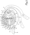
- the clamping of the clamping end of the saw blade 5 against the contact surface 4 takes place by means of a tendon in the form of a two-armed lever 7, which is mounted on a bearing pin forming a pivot axis 8.
- the pivot axis 8 of the lever 7 is arranged at a distance from the contact surface 4 parallel to the lifting axis, and from the pivot axis 8 extends into the interior of the clamping body 2 into an inner arm 9 of the lever 7, which has an eccentric curve 10 at its inner end.
- the inner arm 9 of the eccentric curve 10 By pivoting the lever 7 about the pivot axis 8, the inner arm 9 of the eccentric curve 10, the eccentricity of which is related to the pivot axis 8, can be brought into contact with the clamping end of the saw blade 5, with the inner arm 9 and the clamping end of the saw blade 5 between the Swivel axis 8 and the contact surface 4, a tension arises, the force of which closes via the clamping body 2.
- the lever 7 also has an outer arm 11, the The effective length is significantly greater than that of the inner arm 9 of the lever 7.
- the outer arm 11 runs with a greater curvature in order to then take on an arc shape which is adapted to the outer roundness of the clamping body 2.
- the weakly curved area of the outer arm 11 of the lever 7 runs approximately concentrically to the lifting axis when tensioning a thinner saw blade 5, as is shown by the representation of the lever 7 in solid lines in FIG. 2.
- the lever 7 assumes the position which corresponds to the inner illustration in dashed lines in FIG. 2.
- the open position of the lever 7, in which the shorter inner arm 9 is pivoted so far away from the contact surface 4 that the saw blade 5 can be replaced, is indicated in Fig. 2 by the outer representation in dashed lines.
- the overall approximately C-shaped lever 4 has a free handle end 12 which is slightly angled outwards against the C curvature, so that the handle end 12 can be easily grasped even in the position which is almost in contact with the clamping body 2.
- the clamping body 2 has an incision 14, which runs in the circumferential direction and is symmetrical to its central cross-sectional plane, the flanks of which are formed by radial surfaces 13 in the lower end region. Between the two opposing radial surfaces 13 of the incision 14 is the part of the lever 7 which dips into the clamping body 2, in particular its shorter inner arm 9, wherein the pivot axis 8 for the lever 7 bridges the incision 14.
- the groove-shaped incision 14, which extends approximately over half the circumference of the tensioning body 2 has an inclined base 15 outside the pivoting range of the lever 7, which gradually rises from the lowest point to the circumferential side of the tensioning body 2.
- a tension spring 17 is arranged, which is fixed with its inner end to a bolt 18 , which also bridges the notch 14 of the clamping body 2 adjacent to the pivot axis 8.
- the spring 17 which follows from the rising base 15 of the incision 14 is articulated at its other end to the outer arm 11 of the lever 7 near the handle end 12 by being likewise suspended there in a bolt 19 or the like.
- the tension spring 17 strives to always keep the lever 7 in the tensioned position, thus supporting the tensioning force, translated via the longer outer arm 11 and the shorter inner arm 9 of the lever 7, which represents an additional safeguard particularly in the event of vibrations occurring during operation. Otherwise, the tension spring 17 does not interfere with the mobility of the lever 7 because it is arranged on the circumferential side of the clamping body 2 remote from the outer arm 11 of the lever 7.
Landscapes
- Engineering & Computer Science (AREA)
- Mechanical Engineering (AREA)
- Sawing (AREA)
Abstract
Description
- Die Erfindung bezieht sich auf eine Vorrichtung zur Aufnahme des Spannendes eines einendig einspannbaren, hin- und herbeweglichen Sägeblattes der im Gattungsbegriff des Patentanspruchs 1 näher bezeichneten Art.
- Eine solche Spannvorrichtung ist aus der DE 30 06 299 A1 bekannt. Dort wird der Spannkörper von einer Hülse umgeben, die gegenüber der Sägeblattaufnahme verdrehbar ist und an ihrer Innenseite die Exzenterkurve aufweist. An dieser Exzenterkurve stützt sich ein Spannbacken ab, der als Spannglied quer zur Sägeblattaufnahme über die Exzenterkurve durch Verdrehen der Hülse verschieblich ist. Die Aufbringung einer ausreichenden Spannkraft für das Sägeblatt ist bei der bekannten Spannvorrichtung problematisch, so kann sich dort insbesondere bei den auftretenden Vibrationen die Spannhülse zurückdrehen und sich das Sägeblatt lösen.
- Es ist ferner eine Aufnahmevorrichtung für das Spannende eines Sägeblattes bekannt, die mit einem zweiarmigen Hebel ausgestattet ist, vgl. US 3,555,678. Dort sitzt an dem kürzeren Hebelarm zumindest ein Zapfen, der formschlüssig in eine entsprechende Aussparung am Spannende des Sägeblattes eingreift. Eine ähnliche Spannvorrichtung geht aus der EP 0 582 326 A1 hervor, hier ist das Spannglied an einem schwenkbaren Körper angeordnet, welcher mittels eines in einer Kulisse geführten Betätigungsgliedes in seiner Spannstellung festgeklemmt werden kann. Eine unmittelbare Beaufschlagung des Spannendes des Sägeblattes mittels eines reibschlüssigen Spanngliedes ist bei diesen bekannten Vorrichtungen nicht vorgesehen.
- Aufgabe der vorliegenden Erfindung ist es, eine Spannvorrichtung der gattungsgemäßen Art zu schaffen, bei der von Hand hohe Spannkräfte einfach aufgebracht werden können und aufgrund der entsprechend hohen Reibkräfte ein selbstätiges Lösen des Sägeblattes unterbunden ist.
- Diese Aufgabe wird bei einer gattungsbildenden Vorrichtung nach der Erfindung durch die kennzeichnenden Merkmale des Patentanspruchs 1 gelöst.
- Für die Erfindung ist die Ausbildung des Spanngliedes als zweiarmiger Hebel wesentlich, wobei es die Hebelübersetzung zwischen dem kürzeren Innenarm und dem längeren, zu betätigenden Außenarm ermöglicht, über die das Einspannende des Sägeblattes unmittelbar beaufschlagende Exzenterkurve hohe Spannkräfte aufzubringen, wodurch sich die Spannvorrichtung selbst sichert und ein Lösen des Sägeblattes nicht auftritt. Die Krümmung des längeren Außenarms des zweiarmigen Spannhebels in Umfangsrichtung des Spannkörpers vermeidet störende Überstände auch dann, wenn aufgrund der Beaufschlagung eines dickeren Sägeblattes der gebogene Außenarm des Spannhebels nicht bis dicht an den Spannkörper heran in der Klemmlage geschwenkt werden kann. Somit ist es mit der erfindungsgemäßen Spannvorrichtung erreicht, ein einendig einspannbares Sägeblatt, wie insbesondere das Sägeblatt einer Stichsäge, auf besonders einfache und wirkungsvolle Weise werkzeuglos spannen zu können.
- Vorteilhafte Ausgestaltungsmerkmale der Erfindung ergeben sich aus den Unteransprüchen. Hier ist insbesondere die Beaufschlagung des zweiarmigen Spannhebels durch eine Feder hervorzuheben, die in Spannrichtung wirkt.
- Vor allem bei Anlenkung dieser Feder als Zugfeder am Griffende des Außenarms des Spannhebels wird die Hebelübersetzung für die Verstärkung der Federkraft genutzt, durch die sich eine erhöhte Spannkraft am Stirnende des kürzeren Innenarms des Spannhebels ergibt.
- Die Erfindung wird nachfolgend anhand der Zeichnung an einem Ausführungsbeispiel noch näher erläutert. Dabei zeigen:
- Fig. 1
- eine perspektivische Ansicht einer Spannvorrichtung für ein Stichsägeblatt und
- Fig. 2
- einen Querschnitt durch die Spannvorrichtung nach Fig. 1 in Höhe der Spannstelle des Stichsägeblattes.
- Im einzelnen zeigt Fig. 1 den Stößel 1 einer Stichsäge, an dessen Unterende eine werkzeuglos spannbare Aufnahme für das Einspannende eines Stichsägeblattes 5 angeordnet ist, die einen mittels eines Spannstiftes 3 mit dem Stößel 1 verbundenen Spannkörper 2 aufweist. Das Stichsägeblatt 5 wird am Einspannende so in der Spannvorrichtung fixiert, daß es im wesentlichen in der Diametralebene des Stößels 1 liegt. Der Spannkörper 2 hat eine zylindrische Hüllform, die koaxial zum Stößel 1 ist.
- Wie man Fig. 2 weiter entnimmt, ist etwa in der Diametralebene dieser zylindrischen Hüllform des Spannkörpers 2 und damit in der Diametralebene des Stößels 1 am letzteren eine Anlagefläche 4 gebildet, gegen die das Einspannende des Sägeblattes 5 zur Anlage gebracht werden kann, wo nach es in Eingriff mit Formschlußkonturen 6 steht, die das Sägeblatt in seiner Spannlage bei Anlage an der Anlagefläche 4 gegen ein Verschieben in Hubrichtung sichern.
- Die Verspannung des Einspannendes des Sägeblattes 5 gegen die Anlagefläche 4 erfolgt mittels eines Spanngliedes in Gestalt eines zweiarmigen Hebels 7, der an einem eine Schwenkachse 8 bildenden Lagerbolzen gelagert ist. Die Schwenkachse 8 des Hebels 7 ist mit Abstand gegenüber der Anlagefläche 4 parallel zur Hubachse angeordnet, und von der Schwenkachse 8 aus erstreckt sich in das Innere des Spannkörpers 2 hinein ein Innenarm 9 des Hebels 7, der an seinem Innenende eine Exzenterkurve 10 hat. Durch Verschwenken des Hebels 7 um die Schwenkachse 8 kann dessen Innenarm 9 mit der Exzenterkurve 10, deren Exzentrizität auf die Schwenkachse 8 bezogen ist, in Anlage am Einspannende des Sägeblattes 5 gebracht werden, wobei über den Innenarm 9 und das Einspannende des Sägeblattes 5 zwischen der Schwenkachse 8 und der Anlagefläche 4 eine Verspannung entsteht, deren Kraft sich über den Spannkörper 2 schließt.
- Der Hebel 7 weist ferner einen Außenarm 11 auf, dessen Wirklänge wesentlich größer als die des Innenarms 9 des Hebels 7 ist. Unmittelbar von der Schwenkachse 8 aus nach außen hin verläuft der Außenarm 11 mit einer stärkeren Krümmung, um daran anschließend eine Bogenform einzunehmen, die an die Außenrundung des Spannkörpers 2 angepaßt ist. Somit verläuft der schwächer gekrümmte Bereich des Außenarms 11 des Hebels 7 bei Spannen eines dünneren Sägeblattes 5 etwa konzentrisch zur Hubachse, wie es die Darstellung des Hebels 7 in ausgezogenen Linien in Fig. 2 wiedergibt. Beim Spannen eines dickeren Sägeblattes nimmt der Hebel 7 diejenige Lage ein, die in Fig. 2 der inneren Darstellung in gestrichten Linien entspricht. Die Offenlage des Hebels 7, in der der kürzere Innenarm 9 von der Anlagefläche 4 so weit weggeschwenkt ist, daß das Sägeblatt 5 ausgestauscht werden kann, ist in Fig. 2 durch die äußere Darstellung in gestrichten Linien angedeutet.
- Der insgesamt etwa C-förmige Hebel 4 hat ein freies Griffende 12, welches entgegen der C-Krümmung leicht nach außen hin abgewinkelt ist, so kann man auch in der nahezu am Spannkörper 2 anliegenden Lage das Griffende 12 leicht erfassen.
- Wie Fig. 1 deutlich macht, hat der Spannkörper 2 einen in Umfangsrichtung verlaufenden, symmetrisch zu seiner mittigen Querschnittsebene ausgebildeten Einschnitt 14, dessen Flanken im tieferen Endbereich von Radialflächen 13 gebildet werden. Zwischen den beiden einander gegenüberliegenden Radialflächen 13 des Einschnittes 14 ist der in den Spannkörper 2 eintauchende Teil des Hebels 7, insbesondere dessen kürzerer Innenarm 9 angeordnet, wobei die Schwenkachse 8 für den Hebel 7 den Einschnitt 14 überbrückt. Der sich etwa über den halben Umfang des Spannkörpers 2 erstreckende, nutförmige Einschnitt 14 hat außerhalb des Schwenkbereichs des Hebels 7 einen geneigten Grund 15, der von der tiefsten Stelle allmählich bis zur Umfangsseite des Spannkörpers 2 ansteigt. In diesem Bereich des Einschnittes 14, der auf der vom längeren Außenarm 11 abliegenden Umfangseite des Spannkörpers 2 angeordnet ist und der hier durch gegenüber der Radialrichtung geschrägte Flanken 20 begrenzt sein kann, ist eine Zugfeder 17 angeordnet, die mit ihrem Innenende an einem Bolzen 18 festgelegt ist, der benachbart der Schwenkachse 8 ebenfalls den Einschnitt 14 des Spannkörpers 2 überbrückt. Die von da ab dem ansteigenden Grund 15 des Einschnittes 14 folgende Feder 17 ist mit ihrem anderen Ende am Außenarm 11 des Hebels 7 nahe dem Griffende 12 angelenkt, indem sie dort ebenfalls in einen Bolzen 19 oder dergleichen eingehängt ist. Die Zugfeder 17 ist bestrebt, den Hebel 7 stets in der Spannstellung zu halten, sie unterstützt somit, übersetzt über den längeren Außenarm 11 und den kürzeren Innenarm 9 des Hebels 7 die Spannkraft, was insbesondere bei den auftretenden Vibrationen im Betrieb eine zusätzliche Sicherung darstellt. Im übrigen stört die Zugfeder 17 die Beweglichkeit des Hebels 7 nicht, weil sie auf der vom Außenarm 11 des Hebels 7 abgelegenen Umfangsseite des Spannkörpers 2 angeordnet ist.
Claims (9)
- Vorrichtung zur Aufnahme des Spannendes eines einendig einspannbaren, hin- und herbeweglichen Sägeblattes, wie das einer Stichsäge, mit einer mit benachbarten oder eingeformten Formschlußkonturen versehenen Anlagefläche in einem Spannkörper, gegen die das Spannende des Sägeblattes mittels eines am Spannkörper gelagerten Spanngliedes und einer Exzenterkurve verspannbar ist,
dadurch gekennzeichnet,
daß das Spannglied ein zweiarmiger Hebel mit einem kürzeren Innenarm (9) und mit einem längeren, in Umfangsrichtung des Spannkörpers (2) gebogenen Außenarm (11) mit einem freien Griffende (12) ist und daß am Stirnende des kürzeren Innenarms (9) die Exzenterkurve (10) angeordnet ist, welche in der Spannlage das Spannende des Stichsägeblattes (5) unmittelbar beaufschlagt. - Vorrichtung nach Anspruch 1,
dadurch gekennzeichnet,
daß der Spannkörper (2) eine zylindrische Hüllform hat und die Anlagefläche (4) etwa in einer Diametralebene dieser Hüllform liegt, wobei der Hebel (7) gegenüber der Anlagefläche (4) am Spannkörper (2) nahe dessen Umfangsseite gelagert ist. - Vorrichtung nach Anspruch 1 oder 2,
dadurch gekennzeichnet,
daß die Schwenkachse (8) des Hebels (7) mit der Hubachse des Spannkörpers (2) parallel ist. - Vorrichtung nach Anspruch 2 oder 3,
dadurch gekennzeichnet,
daß der Spannkörper (2) einen Absatz mit einer Radialfläche (13) hat, auf welcher die Schwenkachse (8) des Hebels (7) angeordnet ist. - Vorrichtung nach Anspruch 4,
dadurch gekennzeichnet,
daß der Spannkörper (2) einen in Umfangsrichtung verlaufenden sowie auf Höhe der Anlagefläche (4) liegenden Einschnitt (14) hat, der von zwei Radialflächen (13) begrenzt ist, zwischen die der Hebel (7) mit seinem Innenarm (9) eintaucht. - Vorrichtung nach einem der Ansprüche 1 - 5,
dadurch gekennzeichnet,
daß der Hebel (7) etwa C-förmig ist, wobei das freie Griffende (12) entgegen der C-Krümmung abgewinkelt ist. - Vorrichtung nach einem der Ansprüche 1 - 6,
dadurch gekennzeichnet,
daß an dem Hebel (7) eine in Spannrichtung wirkende Feder (17) angreift. - Vorrichtung nach Anspruch 7,
dadurch gekennzeichnet,
daß die Feder (17) eine Zugfeder ist, die am Spannkörper (2) sowie am oder nahe dem Griffende (12) am Außenarm (11) des Hebels (7) angelenkt ist und sich im wesentlichen auf der dem Außenarm (11) des Hebels (7) abgelegenen Umfangsseite des Spannkörpers (2) erstreckt. - Vorrichtung nach Anspruch 8,
dadurch gekennzeichnet,
daß die Feder (17) teilweise in den Einschnitt (14) des Spannkörpers (2) eintaucht.
Applications Claiming Priority (2)
| Application Number | Priority Date | Filing Date | Title |
|---|---|---|---|
| DE19501635A DE19501635A1 (de) | 1995-01-20 | 1995-01-20 | Vorrichtung zur Aufnahme eines einendig einspannbaren Sägeblattes |
| DE19501635 | 1995-01-20 |
Publications (2)
| Publication Number | Publication Date |
|---|---|
| EP0722802A1 true EP0722802A1 (de) | 1996-07-24 |
| EP0722802B1 EP0722802B1 (de) | 1998-11-11 |
Family
ID=7751915
Family Applications (1)
| Application Number | Title | Priority Date | Filing Date |
|---|---|---|---|
| EP95119938A Expired - Lifetime EP0722802B1 (de) | 1995-01-20 | 1995-12-18 | Vorrichtung zur Aufnahme eines einendig einspannbaren Sägeblattes |
Country Status (3)
| Country | Link |
|---|---|
| US (1) | US5722309A (de) |
| EP (1) | EP0722802B1 (de) |
| DE (2) | DE19501635A1 (de) |
Cited By (4)
| Publication number | Priority date | Publication date | Assignee | Title |
|---|---|---|---|---|
| EP0749796A1 (de) * | 1995-06-19 | 1996-12-27 | Metabowerke GmbH & Co. | Vorrichtung zur Aufnahme des Spannendes eines Sägeblattes |
| US6662698B2 (en) | 2002-01-02 | 2003-12-16 | Black & Decker Inc. | Saw blade clamp system |
| EP1719569A1 (de) | 2005-05-03 | 2006-11-08 | Metabowerke GmbH | Vorrichtung zum Einspannen eines hin- und hergehend antreibbaren Werkzeugs und motorisch angetriebenes Werkzeuggerät |
| EP2499978A1 (de) * | 2011-03-18 | 2012-09-19 | WSEngineering GmbH & Co. KG | Halterung für ein Oszillationssägeblatt |
Families Citing this family (20)
| Publication number | Priority date | Publication date | Assignee | Title |
|---|---|---|---|---|
| DE19702407C2 (de) * | 1997-01-24 | 1999-02-18 | Festo Tooltechnic Gmbh & Co | Schnellspannvorrichtung an einer Werkstück-Bearbeitungsmaschine |
| US5987758A (en) * | 1997-10-28 | 1999-11-23 | Ryobi North America, Inc. | Quick-change blade clamp |
| US6467177B2 (en) | 1998-07-02 | 2002-10-22 | Black & Decker Inc. | Reciprocating saw blade clamp |
| US6112420A (en) * | 1999-08-10 | 2000-09-05 | S-B Power Tool Company | Blade clamp for reciprocating saw |
| JP4244615B2 (ja) * | 2002-04-22 | 2009-03-25 | 日立工機株式会社 | 電動切断機 |
| CN2617509Y (zh) * | 2003-04-14 | 2004-05-26 | 苏州宝时得电动工具有限公司 | 工作元件的快换夹紧机构 |
| US6848186B1 (en) * | 2003-08-18 | 2005-02-01 | Rexon Industrial Corp., Ltd. | Saw blade clamping device |
| US7871080B2 (en) * | 2004-01-16 | 2011-01-18 | Robert Bosch Gmbh | Tool-less blade clamping apparatus for a reciprocating tool |
| EP1661652A1 (de) * | 2004-11-25 | 2006-05-31 | Jiangsu Golden Harbour Enterprise Ltd. | Sägeblattspannvorrichtung für eine Stichsäge |
| JP4573637B2 (ja) * | 2004-12-02 | 2010-11-04 | 株式会社マキタ | 往復動式作業工具 |
| CN200970657Y (zh) * | 2006-05-25 | 2007-11-07 | 南京德朔实业有限公司 | 锯片夹紧装置 |
| DE102006025768A1 (de) * | 2006-05-31 | 2007-12-13 | Robert Bosch Gmbh | Hubsäge mit einer Befestigungseinrichtung für ein Sägeblatt |
| US8813372B2 (en) | 2007-09-14 | 2014-08-26 | Milwaukee Electric Tool Corporation | Blade clamp mechanism |
| US8230607B2 (en) | 2008-05-09 | 2012-07-31 | Milwaukee Electric Tool Corporation | Keyless blade clamp for a power tool |
| US8555516B2 (en) * | 2010-03-25 | 2013-10-15 | Black & Decker Inc. | Pivoting blade retainer |
| MX2013010225A (es) | 2011-03-07 | 2014-01-08 | Infusion Brands Inc | Sierra reciprocante de doble cuchilla. |
| US9321112B2 (en) | 2011-05-18 | 2016-04-26 | Black & Decker Inc. | Power saw tool |
| US9559628B2 (en) | 2013-10-25 | 2017-01-31 | Black & Decker Inc. | Handheld power tool with compact AC switch |
| DE102015218339A1 (de) * | 2015-09-24 | 2017-03-30 | Robert Bosch Gmbh | Handgeführte Hubsäge mit einer Verlaufskorrekturvorrichtung und Verfahren zur Verlaufskorrektur |
| US12420345B2 (en) | 2022-02-22 | 2025-09-23 | Techtronic Cordless Gp | Blade clamp for reciprocating saw |
Citations (8)
| Publication number | Priority date | Publication date | Assignee | Title |
|---|---|---|---|---|
| US3555678A (en) | 1968-01-23 | 1971-01-19 | Gen Appliance Corp | Electric culinary device |
| FR2361189A1 (fr) * | 1976-08-09 | 1978-03-10 | American Safety Equip | Mecanisme de fixation de lame de scie oscillante a demontage rapide |
| DE3006299A1 (de) | 1980-02-20 | 1981-08-27 | Robert Bosch Gmbh, 7000 Stuttgart | Stichsaege |
| DE3030855A1 (de) * | 1980-02-25 | 1981-09-10 | Widder Corp., Naugatuck, Conn. | Saege und saegeblatt fuer diese saege |
| DE3118759A1 (de) * | 1981-05-12 | 1982-12-02 | Licentia Patent-Verwaltungs-Gmbh, 6000 Frankfurt | Vorrichtung zur halterung des saegeblatts am stoessel einer stichsaege |
| GB2192363A (en) * | 1986-07-07 | 1988-01-13 | Bosch Gmbh Robert | Clamping device for saw blades |
| EP0339357A2 (de) * | 1988-04-29 | 1989-11-02 | C. & E. FEIN GmbH & Co. | Schneidmesser |
| EP0582326A1 (de) | 1992-07-29 | 1994-02-09 | Skil Europe B.V. | Sägeblattfestspannvorrichtung |
Family Cites Families (4)
| Publication number | Priority date | Publication date | Assignee | Title |
|---|---|---|---|---|
| US3542097A (en) * | 1968-05-02 | 1970-11-24 | Singer Co | Chuck assembly for sabre saws |
| US4648182A (en) * | 1979-08-01 | 1987-03-10 | Hoffman Simon J | Holder for saber saw blade |
| US4601477A (en) * | 1985-01-10 | 1986-07-22 | The Singer Company | Sabre saw blade clamp |
| US5443276A (en) * | 1994-07-22 | 1995-08-22 | S-B Power Tool Company | Self-locking blade holder |
-
1995
- 1995-01-20 DE DE19501635A patent/DE19501635A1/de not_active Ceased
- 1995-12-18 DE DE59504217T patent/DE59504217D1/de not_active Expired - Lifetime
- 1995-12-18 EP EP95119938A patent/EP0722802B1/de not_active Expired - Lifetime
-
1996
- 1996-01-16 US US08/584,948 patent/US5722309A/en not_active Expired - Lifetime
Patent Citations (8)
| Publication number | Priority date | Publication date | Assignee | Title |
|---|---|---|---|---|
| US3555678A (en) | 1968-01-23 | 1971-01-19 | Gen Appliance Corp | Electric culinary device |
| FR2361189A1 (fr) * | 1976-08-09 | 1978-03-10 | American Safety Equip | Mecanisme de fixation de lame de scie oscillante a demontage rapide |
| DE3006299A1 (de) | 1980-02-20 | 1981-08-27 | Robert Bosch Gmbh, 7000 Stuttgart | Stichsaege |
| DE3030855A1 (de) * | 1980-02-25 | 1981-09-10 | Widder Corp., Naugatuck, Conn. | Saege und saegeblatt fuer diese saege |
| DE3118759A1 (de) * | 1981-05-12 | 1982-12-02 | Licentia Patent-Verwaltungs-Gmbh, 6000 Frankfurt | Vorrichtung zur halterung des saegeblatts am stoessel einer stichsaege |
| GB2192363A (en) * | 1986-07-07 | 1988-01-13 | Bosch Gmbh Robert | Clamping device for saw blades |
| EP0339357A2 (de) * | 1988-04-29 | 1989-11-02 | C. & E. FEIN GmbH & Co. | Schneidmesser |
| EP0582326A1 (de) | 1992-07-29 | 1994-02-09 | Skil Europe B.V. | Sägeblattfestspannvorrichtung |
Cited By (4)
| Publication number | Priority date | Publication date | Assignee | Title |
|---|---|---|---|---|
| EP0749796A1 (de) * | 1995-06-19 | 1996-12-27 | Metabowerke GmbH & Co. | Vorrichtung zur Aufnahme des Spannendes eines Sägeblattes |
| US6662698B2 (en) | 2002-01-02 | 2003-12-16 | Black & Decker Inc. | Saw blade clamp system |
| EP1719569A1 (de) | 2005-05-03 | 2006-11-08 | Metabowerke GmbH | Vorrichtung zum Einspannen eines hin- und hergehend antreibbaren Werkzeugs und motorisch angetriebenes Werkzeuggerät |
| EP2499978A1 (de) * | 2011-03-18 | 2012-09-19 | WSEngineering GmbH & Co. KG | Halterung für ein Oszillationssägeblatt |
Also Published As
| Publication number | Publication date |
|---|---|
| US5722309A (en) | 1998-03-03 |
| DE59504217D1 (de) | 1998-12-17 |
| DE19501635A1 (de) | 1996-08-01 |
| EP0722802B1 (de) | 1998-11-11 |
Similar Documents
| Publication | Publication Date | Title |
|---|---|---|
| EP0722802A1 (de) | Vorrichtung zur Aufnahme eines einendig einspannbaren Sägeblattes | |
| EP0749796B1 (de) | Vorrichtung zur Aufnahme des Spannendes eines Sägeblattes | |
| DE69738365T2 (de) | Schwenkbare klammer | |
| EP2162262B1 (de) | Zwinge und verfahren zur herstellung einer zwinge | |
| EP0699054B1 (de) | Chirurgisches instrument mit zwei trennbaren griffbranchen | |
| WO1994023215A1 (de) | Klemmvorrichtung | |
| DE4102011A1 (de) | Einrichtung zum festspannen des saegeblatts von handgefuehrten stichsaegemaschinen | |
| DE3532251A1 (de) | Bolzenschweisspistole | |
| DE3433106A1 (de) | Wischarm, insbesondere fuer wischanlagen an kraftfahrzeugen | |
| CH659613A5 (de) | Befestigungskloben. | |
| WO2004020130A1 (de) | Werkzeug zur spanenden bearbeitung | |
| DE3636500A1 (de) | Schutzhaube fuer handwerkzeugmaschinen, insbesondere schleifmaschinen | |
| EP0541932A1 (de) | Vorrichtung zum Befestigen und Halten eines Hilfsinstrumentes an einem medizinischen Instrument | |
| EP1413398B1 (de) | Schnellspanner mit einem Verriegelungselement | |
| DE4033302A1 (de) | Scheibenwischerarm | |
| DE19541544A1 (de) | Spannwerkzeug | |
| DE2819060C2 (de) | Verfahren zum Auskleiden eines Gehäuses einer Auflösevorrichtung sowie mit einer Einlage versehene Auflösevorrichtung | |
| DE3045269C2 (de) | ||
| DE3304206C2 (de) | ||
| DE2801828A1 (de) | Loesbarer klemmhalter mit einem handgriff zum aufsetzen vorzugsweise auf den spindelhals einer bohrmaschine | |
| EP1074327B1 (de) | Stichsäge mit Pendelbewegung des Sägeblattes | |
| EP0300473B1 (de) | Druckkappe für Spanneinrichtungen | |
| DE3150966A1 (de) | Spannbacke | |
| EP0522587A2 (de) | Gripzange | |
| DE19917407C1 (de) | Schirmanschlußklemme |
Legal Events
| Date | Code | Title | Description |
|---|---|---|---|
| PUAI | Public reference made under article 153(3) epc to a published international application that has entered the european phase |
Free format text: ORIGINAL CODE: 0009012 |
|
| AK | Designated contracting states |
Kind code of ref document: A1 Designated state(s): DE FR GB IT |
|
| 17P | Request for examination filed |
Effective date: 19960912 |
|
| GRAG | Despatch of communication of intention to grant |
Free format text: ORIGINAL CODE: EPIDOS AGRA |
|
| GRAG | Despatch of communication of intention to grant |
Free format text: ORIGINAL CODE: EPIDOS AGRA |
|
| GRAH | Despatch of communication of intention to grant a patent |
Free format text: ORIGINAL CODE: EPIDOS IGRA |
|
| 17Q | First examination report despatched |
Effective date: 19980528 |
|
| GRAH | Despatch of communication of intention to grant a patent |
Free format text: ORIGINAL CODE: EPIDOS IGRA |
|
| GRAA | (expected) grant |
Free format text: ORIGINAL CODE: 0009210 |
|
| AK | Designated contracting states |
Kind code of ref document: B1 Designated state(s): DE FR GB IT |
|
| GBT | Gb: translation of ep patent filed (gb section 77(6)(a)/1977) |
Effective date: 19981113 |
|
| REF | Corresponds to: |
Ref document number: 59504217 Country of ref document: DE Date of ref document: 19981217 |
|
| ITF | It: translation for a ep patent filed | ||
| ET | Fr: translation filed | ||
| PLBE | No opposition filed within time limit |
Free format text: ORIGINAL CODE: 0009261 |
|
| STAA | Information on the status of an ep patent application or granted ep patent |
Free format text: STATUS: NO OPPOSITION FILED WITHIN TIME LIMIT |
|
| 26N | No opposition filed | ||
| REG | Reference to a national code |
Ref country code: GB Ref legal event code: IF02 |
|
| PGFP | Annual fee paid to national office [announced via postgrant information from national office to epo] |
Ref country code: IT Payment date: 20091222 Year of fee payment: 15 |
|
| PG25 | Lapsed in a contracting state [announced via postgrant information from national office to epo] |
Ref country code: IT Free format text: LAPSE BECAUSE OF NON-PAYMENT OF DUE FEES Effective date: 20101218 |
|
| PGFP | Annual fee paid to national office [announced via postgrant information from national office to epo] |
Ref country code: GB Payment date: 20121218 Year of fee payment: 18 |
|
| PGFP | Annual fee paid to national office [announced via postgrant information from national office to epo] |
Ref country code: FR Payment date: 20130123 Year of fee payment: 18 Ref country code: DE Payment date: 20130220 Year of fee payment: 18 |
|
| REG | Reference to a national code |
Ref country code: DE Ref legal event code: R119 Ref document number: 59504217 Country of ref document: DE |
|
| GBPC | Gb: european patent ceased through non-payment of renewal fee |
Effective date: 20131218 |
|
| REG | Reference to a national code |
Ref country code: FR Ref legal event code: ST Effective date: 20140829 |
|
| REG | Reference to a national code |
Ref country code: DE Ref legal event code: R119 Ref document number: 59504217 Country of ref document: DE Effective date: 20140701 |
|
| PG25 | Lapsed in a contracting state [announced via postgrant information from national office to epo] |
Ref country code: DE Free format text: LAPSE BECAUSE OF NON-PAYMENT OF DUE FEES Effective date: 20140701 |
|
| PG25 | Lapsed in a contracting state [announced via postgrant information from national office to epo] |
Ref country code: FR Free format text: LAPSE BECAUSE OF NON-PAYMENT OF DUE FEES Effective date: 20131231 Ref country code: GB Free format text: LAPSE BECAUSE OF NON-PAYMENT OF DUE FEES Effective date: 20131218 |