EP0715422A2 - Datensynchronisierung in einem CDMA Nachrichtenübertragungssystem - Google Patents
Datensynchronisierung in einem CDMA Nachrichtenübertragungssystem Download PDFInfo
- Publication number
- EP0715422A2 EP0715422A2 EP95402684A EP95402684A EP0715422A2 EP 0715422 A2 EP0715422 A2 EP 0715422A2 EP 95402684 A EP95402684 A EP 95402684A EP 95402684 A EP95402684 A EP 95402684A EP 0715422 A2 EP0715422 A2 EP 0715422A2
- Authority
- EP
- European Patent Office
- Prior art keywords
- signal
- spectrum communication
- spread
- spread spectrum
- correlative
- Prior art date
- Legal status (The legal status is an assumption and is not a legal conclusion. Google has not performed a legal analysis and makes no representation as to the accuracy of the status listed.)
- Withdrawn
Links
- 238000004891 communication Methods 0.000 title claims abstract description 42
- 230000005540 biological transmission Effects 0.000 claims abstract description 52
- 238000001228 spectrum Methods 0.000 claims abstract description 20
- 238000000034 method Methods 0.000 claims description 16
- 230000001360 synchronised effect Effects 0.000 claims description 16
- 238000011084 recovery Methods 0.000 claims description 8
- 238000010586 diagram Methods 0.000 description 17
- 230000006870 function Effects 0.000 description 12
- 230000000694 effects Effects 0.000 description 6
- 230000008569 process Effects 0.000 description 5
- 230000008054 signal transmission Effects 0.000 description 5
- 230000001427 coherent effect Effects 0.000 description 2
- 230000007423 decrease Effects 0.000 description 2
- 238000001514 detection method Methods 0.000 description 2
- 230000010363 phase shift Effects 0.000 description 2
- 230000008859 change Effects 0.000 description 1
- 230000006866 deterioration Effects 0.000 description 1
- 230000000873 masking effect Effects 0.000 description 1
- 238000012986 modification Methods 0.000 description 1
- 230000004048 modification Effects 0.000 description 1
- 230000003287 optical effect Effects 0.000 description 1
Images


Classifications
-
- H—ELECTRICITY
- H04—ELECTRIC COMMUNICATION TECHNIQUE
- H04B—TRANSMISSION
- H04B1/00—Details of transmission systems, not covered by a single one of groups H04B3/00 - H04B13/00; Details of transmission systems not characterised by the medium used for transmission
- H04B1/69—Spread spectrum techniques
- H04B1/707—Spread spectrum techniques using direct sequence modulation
- H04B1/7073—Synchronisation aspects
- H04B1/7075—Synchronisation aspects with code phase acquisition
- H04B1/70755—Setting of lock conditions, e.g. threshold
-
- H—ELECTRICITY
- H04—ELECTRIC COMMUNICATION TECHNIQUE
- H04B—TRANSMISSION
- H04B2201/00—Indexing scheme relating to details of transmission systems not covered by a single group of H04B3/00 - H04B13/00
- H04B2201/69—Orthogonal indexing scheme relating to spread spectrum techniques in general
- H04B2201/707—Orthogonal indexing scheme relating to spread spectrum techniques in general relating to direct sequence modulation
- H04B2201/70701—Orthogonal indexing scheme relating to spread spectrum techniques in general relating to direct sequence modulation featuring pilot assisted reception
Definitions
- the present invention relates to a spread spectrum communication apparatus.
- a code division multiple communication method in which a plurality of communication paths are secured in a single band by using a low correlative feature of spread code so as to increase information transmission speed is available.
- a patent application on a synchronous code division multiple communication apparatus using phase shift modulation U.S. Patent Application Serial No. 233,244, filed on August 26, 1994.
- a receiver has an spread code which is identical to the one used for spectrum-spreading a transmission signal, and by performing correlative operation periodically between the spread code and a received signal, information transmission is performed while the spread code and the received signal are synchronized.
- the transmitter transmits a pilot signal, spectrum-spreaded by using a single spread code, as a preamble for a predetermined period before transmitting the information signal.
- the receiver After the receiver synchronizes the pilot signal with the spread code, the receiver synchronizes a received signal with the code and maintains its synchronous state during information transmission period by holding a clock, for example.
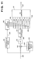
- Fig. 11 is a block diagram illustrating a configuration of a demodulator of the aforesaid conventional code division multiple communication apparatus.
- a modulating method is a phase shift keying and a demodulating method is a coherent detection.
- a received signal 201 which is converted into an intermediate frequency signal is multiplied by a carrier wave 202 which is recovered by a carrier wave recovery circuit 101 at mixer 102.
- the multiplied signal passes through a low pass filter (LPF) 103 and becomes a baseband signal 203.
- the baseband signal 203 is converted into digital multiplexed signals by an AD converter 104.
- LPF low pass filter
- a demodulator of a receiver has digital correlators 106 as many as the number of the multiplexed signals, and the multiplexed digital signals are correlative-demodulated by using a plurality of spread codes 205 generated by a code generator 105 in accordance with a recovery clock 204 recovered by a code synchronization circuit 108, thereby obtaining multiplexed information data of each channel.
- the received multiplexed data to be applied with a correlative operation is represented with 8-bit binary notation with plus or minus sign and a two-phase shift keying is applied, an output from the correlator is between -128 to +127, and the sign bit of the output can be considered as demodulated data.
- Low speed parallel data 206 which is thus demodulated is ultimately changed to a stream of high speed serial data 207 by a parallel-serial converter 107.
- a method of recognizing a data start point or a data end point in a high level of a communication system by inserting a unique word in a data stream, as described above decreases data transmission efficiency. Especially, the decrease in transmission efficiency is remarkable when data is transmitted in a packet.
- the present invention has been made in consideration of the above situation, and has as its object to provide a spread spectrum communication apparatus of high data transmission efficiency by recognizing a start point and/or an end point of information signal transmission in a low level of a communication system without inserting a unique word into a data stream, and by reducing overhead of higher level protocol.
- Another object of the present invention is to obtain the same or similar effect as above, even if transmission performance of a communication path is poor.
- a spread spectrum communication apparatus comprising: correlative demodulation means for performing correlative demodulation on a received pilot signal by using a single spread code; comparing means for comparing a correlative output from the correlative demodulation means to a reference value; and recognition means for recognizing either a start point or an end point of information transmission on the basis of a comparison result by said comparing means.
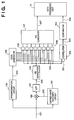
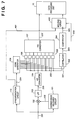
- Fig. 1 is a block diagram illustrating a configuration of a receiver according to a first embodiment of the present invention.
- a code generator 109 outputs the spread code 205 used for correlative demodulation of each information channel as well as a pilot code 301.
- a correlator 302 for a pilot signal (referred as pilot signal correlator, hereinafter) performs correlative demodulation on a received signal with respect to the pilot signal 301. Note that, when the data processing unit 10 processes the received data in a parallel form, the parallel-serial converter 107 is not necessary.
- an output 303 from the correlator 302 is 0. Then, if a transmitter transmits a pilot signal as a preamble signal, after an input signal is synchronized with a spread code and carrier wave is recovered, a received signal power which is obtained by performing correlative demodulation on a pilot signal as a preamble signal appears as an output 303 from a correlator 302 of a receiver.
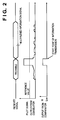
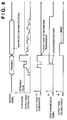
- the timing between a received signal and the output 303 from the correlator 302 is as shown in a timing chart in Fig. 2.
- the pilot signal transmission is terminated. Therefore, an effect of the spread code, included in the received signal, of other information channel on a pilot code appears as the output 303 from the correlator 302, however, the correlation value in the code division multiple communication system is smaller than the value of a signal which appears during the preamble period, as shown in Fig. 2.
- a comparator 304 for comparing the correlation value to a reference value which is shown in Fig. 2 an output 305 from the comparator 304 becomes high level only during the preamble period as shown in Fig. 2.
- a data processing unit 10 recognizes the trailing edge as a changing point from the preamble period to an information transmission period, and processes the subsequent serial data stream 207.
- the comparator 304 will be described later in detail.
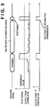
- the transmitter transmits a pilot signal as a postamble signal as shown in Fig. 3, then the output 303 from the correlator 302 of the receiver which received the pilot signal becomes large value as in the preamble period, and the output 305 from the comparator 304 becomes high level. Accordingly, it is possible to recognize a leading edge as the end of the information signal.
- the pilot signal is used only during preamble and postamble periods and is not used during multiple information transmission, however, the present invention is not limited to this, and the present invention can be applied to a case where a pilot code is used as a spread code of one of multiple information channels, for example.
- pilot signal having a lower electric power than that of the preamble signal is superposed on multiplexed data which is being transmitted, and is continually sent in order to recover a carrier wave.
- the pilot signal is generally not modulated by information data.
- Fig. 4 is a block diagram illustrating a configuration of a receiver according to another embodiment of the present invention.
- the same units and elements as those in Fig. 1 are referred by the same reference numerals and explanations of those are omitted.
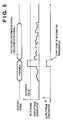
- one of spread codes 306 is a pilot signal as a preamble or postamble signal, and the code 306 is inputted into both the correlator 106 and a pilot signal correlator 307. Focusing on an output 308, corresponding to a received signal by a receiver, from the pilot signal correlator 307, a timing chart which is shown in Fig. 5 or 6 is obtained.
- pilot signal correlator 307 does not demodulates information symbols of the pilot channel, rather measures received signal power of a pilot channel by taking an absolute value of the correlation value. Therefore, the correlator 307 has functions different from those of the correlator 106 for demodulating information symbols.
- total transmission signal power during transmission of a preamble or postamble signal is designed to be about equal to total transmission signal power during information transmission period.
- the pilot signal 306 is included both in the preamble and postamble signals and also in multiplexed information signal, however, the pilot signal in the preamble and postamble signals has signal power which equals to the total transmitted electric power, in contrast, since transmitted electric power is divided into each information channel, the power of the pilot signal during this period is smaller than the power of the signal during the preamble or postamble period
- an output 308 from the pilot signal correlator 307 has a smaller value than a preamble or postamble signal as shown in Fig. 5 or 6.
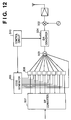
- Fig. 12 shows a configuration of a transmitter.
- Transmitted serial data is converted into low speed parallel data by a serial parallel converter 507, and spreaded by a digital multiplier 506 by using a plurality of spread codes generated by a code generator 505, then added by a digital adder 503. Thereafter, the added data is converted into an analog signal by a digital analog converter 504, further modulated into a signal having radio frequency by a modulator 502, then transmitted from an antenna.
- a control circuit 510 shifts an output from the adder 503 by bit before the output is converted into an analog signal so that total transmission electric power during the preamble period and total transmission electric power during information transmission become about the same. For example, if the output is shifted by three bits, then the total electric power becomes 8 times higher.
- a correct demodulated output can not be obtained as an output from a correlator until a received signal and a spread code are synchronized. It is possible to obtain the desired information transmission start signal in a period when the output 303 from the correlator 302 is unstable with a configuration of the receiver shown in Fig. 1 under condition in which a correlation value is always smaller than a threshold in the comparator. However, if the output from the correlator becomes larger than the threshold, a compared output must be masked in accordance with a state signal indicating an input signal is synchronized with a spread code so as to control the information transmission start signal correctly.
- Fig. 7 is a block diagram illustrating a configuration of a receiver according to a second embodiment.
- the same units and elements as those in Fig. 1 are referred by the same reference numerals and explanations of those are omitted.
- reference numeral 110 denotes a code synchronization circuit having a function for generating a code synchronization signal 401 for indicating that an input signal and a spread code are synchronized, when the input signal and the spread code are synchronized.
- a code synchronization signal becomes high level, and the output 303 from the correlator 302 starts performing correct correlative demodulation of a preamble signal at the same time. Since correlation output in the subsequent period is larger than a threshold, the output 305 from the comparator 304 becomes stable in high level. Accordingly, after information transmission starts, then, a trailing edge is formed in the output 305 from the comparator 304. By latching the code synchronization signal which is high level by using the holding circuit 402 at the trailing edge, then a start point of information transmission can be recognized.
- a purpose of the present embodiment is that the communication system recognizes a start point of information transmission. By resetting the holding circuit 402 in accordance with a signal 403 from a timer or an external device and making the holding circuit 402 in the initial state after the trailing edge appears, the same operation is performed on the next packet. Further, regarding a system using a pilot signal as a spread code for the information transmission, another embodiment expressed with reference to Fig. 4 can be applied.
- a received signal and a spread code are synchronized and that a carrier wave are recovered so as to demodulate a information signal.
- the carrier wave is recovered after an received signal and a spread code are synchronized.
- correct correlative demodulation can not be performed unless the carrier wave is recovered and a baseband signal is demodulated.
- by masking the output from a correlator with a carrier wave recovery signal it is possible to recognize a start point of information transmission correctly.
- Fig. 9 is a block diagram illustrating a configuration of a receiver according to a third embodiment of the present invention.
- the same units and elements as those in Fig. 7 are referred by the same reference numerals and explanations of those are omitted.
- reference numeral 501 denotes a carrier wave recovery signal generator having a function to generates a carrier wave recovery signal 502 when carrier wave is recovered.
- the code synchronization signal 401 in the second embodiment is replaced by the carrier wave recovery signal 502. It is apparent that a correct start point of an information signal can be recognized at a timing represented by a timing chart shown in Fig. 10.
- digital correlative demodulation is performed as an example, however, the third embodiment can be applied when an analog demodulator is used instead of a digital demodulator.
- a changing point from a preamble period to a information transmission period and an end point of information transmission can be determined at lower level of a communication system. Accordingly, it is unnecessary to insert a unique word in a data stream, thereby improving information transmission efficiency. Especially, this is extremely effective for a packet mode data transmission.
- the fourth embodiment describes a case where one of the codes used for demodulation is used as a pilot code, and where a function of a correlator for demodulation and a function of a pilot signal correlator are realized by a single unit.
- Fig. 13 is a block diagram showing a configuration according to the fourth embodiment.
- the AD converter 104 is for converting a baseband multiplexed signal into digital data
- the correlators 106 are digital correlators for performing correlative demodulation of each information channel.
- a comparator 601 is connected to an output of one of correlators 106, and compares the output from the correlator 106 with a reference value.
- the fourth embodiment shows an example in which a code division multiplexed baseband signal is converted into digital data, then the digital data is applied with correlative demodulation in the digital correlators.
- an output signal from a correlator is expressed with eight-bit binary notation with plus or minus sign, then the range of the output signal from the correlator is between -128 and 127. Further, by referring the sign bit of the output signal from the correlator, it is possible to demodulate a modulated data symbol of a corresponding information channel.
- the comparator 601 for comparing an output from a correlator with a predetermined threshold, it is possible to judge whether or not there is modulated data on an information channel or not, in other words, whether or not an information signal is received. It should be noted that the comparator is not for judging a received data symbol, but for judging electrical power of a received signal.
- Fig. 14 is a diagram showing an example of a configuration of a comparator 601
- Fig. 15 is a table used to determine reception of transmission.
- the receiver is not receiving any information signal if an output from the correlator 106 is in a range between -16 to 15.
- an output from the correlator 106 is equal or greater than -16 and equal or less than 15, then either an output from the multi-input OR gate 602 or an output from the multi-input NAND gate 603 becomes low level. Accordingly, an output from the two-input AND gate 604, as the judgment signal, becomes low level, which indicates that electric power of a received signal is lower than a predetermined level, thus, it is possible to recognize that demodulated data is incorrect.
- Fig. 16 is a block diagram according to a fifth embodiment.
- an analog digital converter 701 is for converting a baseband multiplexed signal into digital data
- correlators 702 are digital correlators for performing correlative demodulation of each information channel.
- comparators 705 are connected to outputs from three correlators 702, and compare each output from each correlator 702 with a reference value.
- a decision means 706 is connected to the outputs of the comparators 705, and determines a comparison result by majority in accordance with the output values from the comparators 705.
- an output from a correlator has a certain deviation with respect to a theoretical value because of deterioration of communication path characteristics, noises, or non-linearity of transmission system, and so on. Especially, if characteristics of a communication path are poor, there is a fear that a correct judgment can not be performed by a single comparator 705, differing from the above embodiments.
- a plurality of comparators each of which is identical to the comparator described in the above embodiment are provided for each of the correlators, and each comparator compares an output from each correlator to a reference value. If the transmission path is in ideal state, all the comparators 705 perform the similar operations as in the above embodiment when waiting for a transmitted signal, receiving a preamble signal, and receiving an information signal, and generates a judgment signal.
- a method of obtaining a comparison result from the outputs from a plurality of comparators 705 is not limited to the simple decision by majority as described above, and can be determined by referring a comparison result obtained by comparing an output from a correlator with a different reference value, for example.
- a digital correlative demodulation is described as an example, however, the present invention is not limited to this.
- a correlator for synchronization is included in a synchronization circuit 108, it is possible to recognize a preamble signal and a postamble signal on the basis of a correlation output from the correlator for synchronization.
- the SFD Start Frame Delimiter
- the fifth embodiment in a case where there is a fear that a judgment signal cannot be obtained because of poor characteristics of transmission path and effects of noises, by referring outputs of a plurality of correlators, it is possible to prevent misjudgment by a decision circuit, thereby obtaining the same effect as described in the embodiments.
- the present invention can be applied to a system constituted by a plurality of devices or to an apparatus comprising a single device.
- the object of the present invention can be also achieved by providing a storage medium storing program codes for performing the aforesaid processes to a system or an apparatus, reading the program codes with a computer (e.g., CPU, MPU) of the system or apparatus from the storage medium, then executing the program.
- a computer e.g., CPU, MPU
- the program codes read from the storage medium realize the functions according to the embodiments, and the storage medium storing the program codes constitutes the invention.
- the storage medium such as a floppy disk, a hard disk, an optical disk, a magneto-optical disk, CD-ROM, CD-R, a magnetic tape, a non-volatile type memory card, and ROM can be used for providing the program codes.
- the present invention includes a case where an OS or the like working on the computer performs a part or entire processes in accordance with designations of the program codes and realizes functions according to the above embodiments.
- the present invention also includes a case where, after the program codes read from the storage medium are written in a function extension board which is inserted into the computer or in a memory provided in a function extension unit which is connected to the computer, CPU or the like contained in the function extension board or unit performs a part or entire process in accordance with designations of the program codes and realizes functions of the above embodiments.
Landscapes
- Engineering & Computer Science (AREA)
- Computer Networks & Wireless Communication (AREA)
- Signal Processing (AREA)
- Synchronisation In Digital Transmission Systems (AREA)
Applications Claiming Priority (9)
| Application Number | Priority Date | Filing Date | Title |
|---|---|---|---|
| JP319139/94 | 1994-11-29 | ||
| JP31913994 | 1994-11-29 | ||
| JP6319139A JPH08163084A (ja) | 1994-11-29 | 1994-11-29 | 符号分割多重通信装置 |
| JP5732795A JP3287724B2 (ja) | 1995-03-16 | 1995-03-16 | スペクトラム拡散通信装置 |
| JP57327/95 | 1995-03-16 | ||
| JP5732795 | 1995-03-16 | ||
| JP23533095 | 1995-09-13 | ||
| JP235330/95 | 1995-09-13 | ||
| JP23533095A JP3286128B2 (ja) | 1995-09-13 | 1995-09-13 | 符号分割多重通信方法及び装置 |
Publications (2)
| Publication Number | Publication Date |
|---|---|
| EP0715422A2 true EP0715422A2 (de) | 1996-06-05 |
| EP0715422A3 EP0715422A3 (de) | 2000-07-12 |
Family
ID=27296214
Family Applications (1)
| Application Number | Title | Priority Date | Filing Date |
|---|---|---|---|
| EP95402684A Withdrawn EP0715422A3 (de) | 1994-11-29 | 1995-11-29 | Datensynchronisierung in einem CDMA Nachrichtenübertragungssystem |
Country Status (2)
| Country | Link |
|---|---|
| US (1) | US5768305A (de) |
| EP (1) | EP0715422A3 (de) |
Cited By (4)
| Publication number | Priority date | Publication date | Assignee | Title |
|---|---|---|---|---|
| WO2000039946A1 (en) * | 1998-12-29 | 2000-07-06 | Thomson Licensing S.A. | Handset time synchronisation to a wireless telephone base station |
| WO2000008908A3 (en) * | 1998-08-17 | 2000-07-13 | Samsung Electronics Co Ltd | Device and method for transmitting preamble of access channel in mobile communication system |
| EP1282951A4 (de) * | 2000-05-19 | 2009-04-15 | Intellon Corp | Rahmensteuerungs-codierer/decodierer für robuste ofdm-rahmenübertragungen |
| RU2353063C2 (ru) * | 2004-05-05 | 2009-04-20 | Квэлкомм Инкорпорейтед | Способ и устройство для сокращения служебных сигналов в усовершенствованной восходящей линии связи в системе беспроводной связи |
Families Citing this family (14)
| Publication number | Priority date | Publication date | Assignee | Title |
|---|---|---|---|---|
| JP3567841B2 (ja) * | 2000-02-23 | 2004-09-22 | 株式会社デンソー | 信号同期方式および受信装置 |
| US20030048862A1 (en) * | 2001-09-10 | 2003-03-13 | Hsin-Hsien Lee | Automatic calibration & synchronization for digital asynchronous communication |
| US8059754B2 (en) * | 2006-07-28 | 2011-11-15 | Xg Technology, Inc. | System and method for fast signal acquisition in a wireless digital receiver for wideband signals |
| US8284825B2 (en) * | 2008-06-06 | 2012-10-09 | Maxim Integrated Products, Inc. | Blind channel quality estimator |
| US8165172B2 (en) * | 2008-06-06 | 2012-04-24 | Maxim Integrated Products, Inc. | Robust wideband symbol and frame synchronizer for power-line communication |
| US8315152B2 (en) | 2008-06-06 | 2012-11-20 | Maxim Integrated Products, Inc. | System and method for applying multi-tone OFDM based communications within a prescribed frequency range |
| US8139614B2 (en) * | 2008-06-06 | 2012-03-20 | Maxim Integrated Products, Inc. | Robust narrowband symbol and frame synchronizer for power-line communication |
| US8315341B2 (en) * | 2008-06-06 | 2012-11-20 | Maxim Integrated Products, Inc. | Soft repetition code combiner using channel state information |
| US8149967B2 (en) * | 2008-06-06 | 2012-04-03 | Maxim Integrated Products, Inc. | Combined dual feed-forward and feedback analog and digital automatic gain control for broadband communication |
| US8276025B2 (en) * | 2008-06-06 | 2012-09-25 | Maxim Integrated Products, Inc. | Block interleaving scheme with configurable size to achieve time and frequency diversity |
| US8472576B2 (en) | 2008-06-06 | 2013-06-25 | Maxim Integrated Products, Inc. | Jammer canceller for power-line communication |
| US8320233B2 (en) | 2009-06-12 | 2012-11-27 | Maxim Integrated Products, Inc. | Transmitter and method for applying multi-tone OFDM based communications within a lower frequency range |
| JP6946027B2 (ja) * | 2017-03-17 | 2021-10-06 | 株式会社東芝 | Icカード、携帯可能電子装置、プログラム、処理装置及び処理システム |
| CN110691053A (zh) | 2018-07-06 | 2020-01-14 | 财团法人工业技术研究院 | 封包侦测的软件定义无线电系统及封包侦测方法 |
Family Cites Families (6)
| Publication number | Priority date | Publication date | Assignee | Title |
|---|---|---|---|---|
| US5179574A (en) * | 1986-09-29 | 1993-01-12 | Kabushiki Kaisha Kenwood | Spread PN code signal receiver |
| JP2624964B2 (ja) * | 1987-06-09 | 1997-06-25 | キヤノン株式会社 | 無線通信装置 |
| US5260969A (en) * | 1988-11-14 | 1993-11-09 | Canon Kabushiki Kaisha | Spectrum diffusion communication receiving apparatus |
| JPH04256238A (ja) * | 1991-02-07 | 1992-09-10 | Clarion Co Ltd | スペクトラム拡散変調装置 |
| JP2860614B2 (ja) * | 1991-07-31 | 1999-02-24 | クラリオン株式会社 | スペクトラム拡散通信装置 |
| US5347537A (en) * | 1992-03-17 | 1994-09-13 | Clarion Co., Ltd. | Spread spectrum communication device |
-
1995
- 1995-11-28 US US08/563,792 patent/US5768305A/en not_active Expired - Lifetime
- 1995-11-29 EP EP95402684A patent/EP0715422A3/de not_active Withdrawn
Cited By (7)
| Publication number | Priority date | Publication date | Assignee | Title |
|---|---|---|---|---|
| WO2000008908A3 (en) * | 1998-08-17 | 2000-07-13 | Samsung Electronics Co Ltd | Device and method for transmitting preamble of access channel in mobile communication system |
| AU744158B2 (en) * | 1998-08-17 | 2002-02-14 | Samsung Electronics Co., Ltd. | Device and method for transmitting preamble of access channel in mobile communication system |
| EP1392003A3 (de) * | 1998-08-17 | 2004-04-28 | Samsung Electronics Co., Ltd. | Verfahren zur Übertragung einer Einleitung in einem Zugriffkanal in einem Mobilkommunikationssystem |
| US7054298B1 (en) | 1998-08-17 | 2006-05-30 | Samsung Electronics Co., Ltd. | Device and method for transmitting preamble of access channel in mobile communication system |
| WO2000039946A1 (en) * | 1998-12-29 | 2000-07-06 | Thomson Licensing S.A. | Handset time synchronisation to a wireless telephone base station |
| EP1282951A4 (de) * | 2000-05-19 | 2009-04-15 | Intellon Corp | Rahmensteuerungs-codierer/decodierer für robuste ofdm-rahmenübertragungen |
| RU2353063C2 (ru) * | 2004-05-05 | 2009-04-20 | Квэлкомм Инкорпорейтед | Способ и устройство для сокращения служебных сигналов в усовершенствованной восходящей линии связи в системе беспроводной связи |
Also Published As
| Publication number | Publication date |
|---|---|
| US5768305A (en) | 1998-06-16 |
| EP0715422A3 (de) | 2000-07-12 |
Similar Documents
| Publication | Publication Date | Title |
|---|---|---|
| US5768305A (en) | Identification of start and end points of transmitted data in spread spectrum communication systems | |
| KR100214241B1 (ko) | 스펙트럼 확산 통신 시스템 | |
| US5793794A (en) | Spread spectrum receiving apparatus | |
| US8014379B2 (en) | Correlation of access code for bluetooth synchronization | |
| US20080043702A1 (en) | Method and apparatus for cell search in a communication system | |
| US20040090993A1 (en) | Comma free codes for fast cell search using tertiary synchronization channel | |
| JP2002518960A (ja) | 基地局同期とセクタ識別の高速化を実現するための方法、装置及びシステム | |
| WO2003047117A2 (en) | System and method using primary and secondary synchronization codes during cell search | |
| KR20080101285A (ko) | 무선통신시스템을 위한 파일럿 신호 송수신 방법 및 장치 | |
| KR100548416B1 (ko) | 무선 프레임 동기화 방법 | |
| EP1088412B1 (de) | Rahmensynchronisierungsverfahren und -einrichtungen | |
| JP4230773B2 (ja) | 符号分割多元接続通信用システム | |
| JP2000049750A (ja) | スペクトル拡散無線通信のための同期方法およびシステム | |
| CA2307490C (en) | Control channel for time division multiple access systems | |
| JP3305217B2 (ja) | 通信方法 | |
| US6836518B1 (en) | Synchronization control method for receiver apparatus of data transmission system utilizing orthogonal frequency division multiplex, and data transmission system | |
| US5724382A (en) | Multimode spread spectrum communication system tolerant to varying channel characteristics | |
| JPH09275364A (ja) | スペクトラム拡散通信用同期装置 | |
| US20080279172A1 (en) | Radio Communication Device, Demodulation Method, and Frequency Deflection Correction Circuit | |
| JP3252820B2 (ja) | 復調及び変調回路並びに復調及び変調方法 | |
| JP3286128B2 (ja) | 符号分割多重通信方法及び装置 | |
| JP3287724B2 (ja) | スペクトラム拡散通信装置 | |
| JP4054032B2 (ja) | フレーム同期検出方法 | |
| JP2870534B1 (ja) | マッチドフィルタおよびcdma受信機 | |
| JP4246125B2 (ja) | 受信機 |
Legal Events
| Date | Code | Title | Description |
|---|---|---|---|
| PUAI | Public reference made under article 153(3) epc to a published international application that has entered the european phase |
Free format text: ORIGINAL CODE: 0009012 |
|
| AK | Designated contracting states |
Kind code of ref document: A2 Designated state(s): DE FR GB |
|
| PUAL | Search report despatched |
Free format text: ORIGINAL CODE: 0009013 |
|
| AK | Designated contracting states |
Kind code of ref document: A3 Designated state(s): DE FR GB |
|
| 17P | Request for examination filed |
Effective date: 20001130 |
|
| 17Q | First examination report despatched |
Effective date: 20030415 |
|
| STAA | Information on the status of an ep patent application or granted ep patent |
Free format text: STATUS: THE APPLICATION IS DEEMED TO BE WITHDRAWN |
|
| 18D | Application deemed to be withdrawn |
Effective date: 20030826 |