EP0712684B1 - Träger und Spannvorrichtung für Bearbeitungsvorgänge - Google Patents
Träger und Spannvorrichtung für Bearbeitungsvorgänge Download PDFInfo
- Publication number
- EP0712684B1 EP0712684B1 EP95116556A EP95116556A EP0712684B1 EP 0712684 B1 EP0712684 B1 EP 0712684B1 EP 95116556 A EP95116556 A EP 95116556A EP 95116556 A EP95116556 A EP 95116556A EP 0712684 B1 EP0712684 B1 EP 0712684B1
- Authority
- EP
- European Patent Office
- Prior art keywords
- fixture
- base
- tapered
- contact surfaces
- projections
- Prior art date
- Legal status (The legal status is an assumption and is not a legal conclusion. Google has not performed a legal analysis and makes no representation as to the accuracy of the status listed.)
- Expired - Lifetime
Links
- 238000003754 machining Methods 0.000 title claims description 45
- 238000005520 cutting process Methods 0.000 description 16
- 238000004140 cleaning Methods 0.000 description 15
- 238000010276 construction Methods 0.000 description 10
- 239000000853 adhesive Substances 0.000 description 7
- 230000001070 adhesive effect Effects 0.000 description 7
- 238000004519 manufacturing process Methods 0.000 description 5
- 238000000034 method Methods 0.000 description 4
- 239000000463 material Substances 0.000 description 3
- 239000007787 solid Substances 0.000 description 3
- 239000011159 matrix material Substances 0.000 description 2
- 230000000712 assembly Effects 0.000 description 1
- 238000000429 assembly Methods 0.000 description 1
- 238000003780 insertion Methods 0.000 description 1
- 230000037431 insertion Effects 0.000 description 1
- 230000013011 mating Effects 0.000 description 1
- 230000000717 retained effect Effects 0.000 description 1
Images


Classifications
-
- B—PERFORMING OPERATIONS; TRANSPORTING
- B23—MACHINE TOOLS; METAL-WORKING NOT OTHERWISE PROVIDED FOR
- B23Q—DETAILS, COMPONENTS, OR ACCESSORIES FOR MACHINE TOOLS, e.g. ARRANGEMENTS FOR COPYING OR CONTROLLING; MACHINE TOOLS IN GENERAL CHARACTERISED BY THE CONSTRUCTION OF PARTICULAR DETAILS OR COMPONENTS; COMBINATIONS OR ASSOCIATIONS OF METAL-WORKING MACHINES, NOT DIRECTED TO A PARTICULAR RESULT
- B23Q7/00—Arrangements for handling work specially combined with or arranged in, or specially adapted for use in connection with, machine tools, e.g. for conveying, loading, positioning, discharging, sorting
- B23Q7/14—Arrangements for handling work specially combined with or arranged in, or specially adapted for use in connection with, machine tools, e.g. for conveying, loading, positioning, discharging, sorting co-ordinated in production lines
- B23Q7/1426—Arrangements for handling work specially combined with or arranged in, or specially adapted for use in connection with, machine tools, e.g. for conveying, loading, positioning, discharging, sorting co-ordinated in production lines with work holders not rigidly fixed to the transport devices
-
- B—PERFORMING OPERATIONS; TRANSPORTING
- B23—MACHINE TOOLS; METAL-WORKING NOT OTHERWISE PROVIDED FOR
- B23Q—DETAILS, COMPONENTS, OR ACCESSORIES FOR MACHINE TOOLS, e.g. ARRANGEMENTS FOR COPYING OR CONTROLLING; MACHINE TOOLS IN GENERAL CHARACTERISED BY THE CONSTRUCTION OF PARTICULAR DETAILS OR COMPONENTS; COMBINATIONS OR ASSOCIATIONS OF METAL-WORKING MACHINES, NOT DIRECTED TO A PARTICULAR RESULT
- B23Q3/00—Devices holding, supporting, or positioning work or tools, of a kind normally removable from the machine
- B23Q3/02—Devices holding, supporting, or positioning work or tools, of a kind normally removable from the machine for mounting on a work-table, tool-slide, or analogous part
- B23Q3/10—Auxiliary devices, e.g. bolsters, extension members
- B23Q3/103—Constructional elements used for constructing work holders
-
- B—PERFORMING OPERATIONS; TRANSPORTING
- B23—MACHINE TOOLS; METAL-WORKING NOT OTHERWISE PROVIDED FOR
- B23Q—DETAILS, COMPONENTS, OR ACCESSORIES FOR MACHINE TOOLS, e.g. ARRANGEMENTS FOR COPYING OR CONTROLLING; MACHINE TOOLS IN GENERAL CHARACTERISED BY THE CONSTRUCTION OF PARTICULAR DETAILS OR COMPONENTS; COMBINATIONS OR ASSOCIATIONS OF METAL-WORKING MACHINES, NOT DIRECTED TO A PARTICULAR RESULT
- B23Q3/00—Devices holding, supporting, or positioning work or tools, of a kind normally removable from the machine
- B23Q3/18—Devices holding, supporting, or positioning work or tools, of a kind normally removable from the machine for positioning only
- B23Q3/186—Aligning devices
-
- Y—GENERAL TAGGING OF NEW TECHNOLOGICAL DEVELOPMENTS; GENERAL TAGGING OF CROSS-SECTIONAL TECHNOLOGIES SPANNING OVER SEVERAL SECTIONS OF THE IPC; TECHNICAL SUBJECTS COVERED BY FORMER USPC CROSS-REFERENCE ART COLLECTIONS [XRACs] AND DIGESTS
- Y10—TECHNICAL SUBJECTS COVERED BY FORMER USPC
- Y10S—TECHNICAL SUBJECTS COVERED BY FORMER USPC CROSS-REFERENCE ART COLLECTIONS [XRACs] AND DIGESTS
- Y10S269/00—Work holders
- Y10S269/90—Supporting structure having work holder receiving apertures or projections
Definitions
- the present invention relates to a machining device according to the preamble of claim 1, to a base according to the preamble of claim 16 and to a fixture according to the preamble of claim 17.
- a machining device, base and fixture are known from US-A-4 738 439.
- a fixture such as a plate, a two-sided block or a four-sided block, fixedly mounts onto a table or a pallet of a machining device (also referred to as a machining apparatus or a machine tool), to position and retain a workpiece.
- Conventional fixtures mount directly onto the mount surface of the table or the pallet of the machining apparatus. Therefore, any debris left on the mount surface from a prior machining operation.must be carefully removed before the next fixture is attached to assure a stable connection. Cleaning the mount surface requires time and labor and reduces overall productivity.
- fixtures require high precision positioning on the mount surface of the table of the machining apparatus.
- Such highly precise positioning of fixtures requires the time and skill of an experienced operator. Before each new fixture is attached to the base, the mount surface must be cleaned and the fixture must be carefully and precisely positioned, thereby reducing the efficiency of the entire machining operation.
- the present invention overcomes the above-stated problems of the conventional art.
- a machining device has a base and a fixture.
- the base is fixedly attached to a pallet or a machining table.
- the fixture is mounted on the base, contacting the base only at projecting contact surfaces which project above the mounting surface of the base. Cleaning of the base before a fixture is attached is done efficiently because only the minimized projecting contact surfaces area between the base and the fixture needs to be cleaned to assure stable contact between the base and fixture.
- the base and fixture also include projections and holes for precisely aligning the base and fixture with respect to each other.
- a machining device comprising: a base having a mounting surface, a means for holding a workpiece having a bottom surface, means for fixedly attaching said means for holding a workpiece to said base, said mounting surface having discrete first contact surfaces, and said bottom surface contacting said base only at said first contact surfaces when said means for holding a workpiece is fixedly attached to said base, such that the total contact area is less than the area of each of the bottom surface and the mounting surface.
- the fixture such as a plate, a two-sided block or a four-sided block, which serves as the means for holding a workpiece, contacts and is supported by the projecting contact surfaces (first contact surfaces) provided on the mount surface of the base.
- first contact surfaces first contact surfaces
- the fixture is therefore firmly connected to the base.
- the contacting surfaces of the mount surface of the base is substantially reduced, the labor required for cleaning of cutting chips or the like is significantly reduced, and the efficiency in mounting the fixture to the base is improved.
- the tapered surfaces of the tapered pit and the tapered projection abut each other to precisely position the fixture relative to the base.
- the tapered projection is formed separately from the base body of the base and is fixedly attached to the base body.
- the tapered projection is a separate member, production of a structure comprising the base body and the tapered projection is facilitated without a complicated production operation. Where such a structure is formed by cutting and grinding one solid piece of material, the production is complicated.
- a pit is bored in a top surface of the base body.
- a tapered pin is inserted and fixed into the pit so as to form the tapered projection.
- a plate member may be attached to the base body for providing the projecting contact surface.
- the projected contact surface may also be formed together with the base body which makes it easier to produce the entire base at a cheaper cost.
- the projecting contact surface is formed together with the base body, production costs are reduced compared with the construction where the projecting contact surface is formed separately from the base body. However the production of the base is more complicated if the projecting contact surface areas are formed together with the base body.
- the tapered projection is located near the projected contact surface.
- tapered projection and the projecting contact surface are close to each other, they can be easily cleaned together, and thus reduce the labor for cleaning, compared with a construction where the tapered projection is apart from the projecting contact surface.
- the projecting contact surface on the mount surface of the base contacts a projecting contact surface on the bottom surface of the fixture.
- the fixture If the projected contact surface of the fixture contacts the projected contact surface of the base, the fixture is supported on the base by abutment between both projected contact surfaces of the base and the fixture.
- a base having a mount surface, for fixedly attaching a means for holding a workpiece onto said mount surface, comprising: a discrete first contact surfaces provided on said mount surface to contact a bottom surface of said means for holding a workpiece, and said first contact surface contacting said base only at said bottom surfaces when said means for holding a workpiece is fixedly attached to said base.
- a fixture for holding a workpiece, fixedly mountable on a base comprising: a bottom surface contacting discrete first contact surfaces on a mount surface of said base, and said bottom surface contacting said base only at said first contact surfaces when said fixture is fixedly attached to said base.
- the fixture such as a plate, a two-sided block or a four-sided block, is supported on the base by abutment between the both projected contact surfaces provided on the bottom side of the fixture and the projected contact surface provided on the mount surface of the base.
- the both taper surfaces of the tapered projection and the tapered pit abut each other to precisely position the fixture relative to the base. Therefore, precise positioning of the fixture can be performed even by an ordinary operator. The efficiency in mounting the fixture is thus further improved.
- a machining device comprising a base having a mounting surface, a means for holding a workpiece having a bottom surface, means for fixedly attaching said means for holding a workpiece to said base, said mounting surface having discrete first contact surfaces, said bottom surface having discrete second contact surfaces corresponding to said first contact surfaces, said bottom surface contacting said base only where said first contact surfaces and said second contact surfaces meet when said means for holding a workpiece is fixedly attached to said base, said means for holding a workpiece including at least one separate mounting device, attachable to said means for holding a workpiece, and discrete third contact surfaces, and said at least one separate mounting device contacting said means for holding a workpiece only at said third contact surfaces.
- the plate which serves as the separate mounting device, is supported on the fixture body by abutment between the reverse side of the plate and the projecting contact surface (discrete third contact surface) provided on the mount surface of the fixture body.
- the tapered surfaces of the tapered projection and the tapered pit abut each other to precisely position the plate relative to the fixture body. Therefore, precise positioning of the plate can be performed even by an ordinary operator. The efficiency in connecting the plate to the fixture body is thus improved.
- a workpiece and jigs are fixed to the plate, which is set on a flat table or machining base, prior to mounting the plate to the fixture body.
- Such preparatory setup facilitates changing plate assemblies that include plates, jigs and workpieces, compared with the case where the jigs and a workpiece are fixed to the plate after the plate has been fixed to the fixture body.
- the efficiency in setting or replacing a plate assembly on the fixture body is improved.
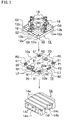
- a base 10 is used to affix a fixture 12 to a pallet 14 of a machining apparatus (or a machine tool).
- Fixture 12 shown in Fig. 1 is generally referred to as a plate. Any other type of fixture can also be used, such as a two-sided block or a four-sided block, and still be within the spirit and scope of the present invention.
- Fixture 12 includes a plurality of reference holes 12a that are arranged in the form of a matrix or grid with a predetermined interval for positioning and fastening various jigs 16 relative to base 10.
- Jigs 16 (for example, a positioning member, a fixing member, or a fastening member such as a clamp), mount on fixture 12 in reference holes 12a.
- Jigs 16 are any type of fixture element that can be used to hold or position a workpiece 18 on fixture 12. Workpiece 18 can thereby be precisely positioned and fixed at a predetermined position on fixture 12.
- Reference holes 12a of fixture 12 may be equidistant from each other or the spacing in one direction may be different from the spacing in another direction.
- the spacing is not necessarily uniform in either direction.
- a grid design is not the only pattern of reference holes 12a. Any pattern is satisfactory as long as various jigs 16 can be mounted where necessary on fixture 12.
- fixture 12 is not necessarily limited to having reference holes 12a as shown in Fig. 1.
- fixture 12 may instead have a plurality of parallel reference slots having a cross sectional shape of an inverted T (hereinafter called T-slots), which are spaced by a predetermined interval or at random intervals.
- T-slots an inverted T
- a fixture without any reference holes or reference slots may also be used.
- Pallet 14 includes a plurality of parallel T-slots 14a formed on its top.
- T-slots 14a extend along one direction from one edge of pallet 14 to another edge and receive corresponding T-slot nuts (not shown in Fig. 1).
- Base 10 fixedly attaches to pallet 14 by using T-slot nuts fitted into appropriate ones of T-slots 14a and by tightening bolts (not shown in Fig. 1) into the T-slot nuts to hold base 10 on pallet 14.
- Two edge locators 14b are mounted on two adjacent sides of pallet 14 respectively. One of edge locators 14b is mounted at an end of T-slot 14a another edge locator 14b is mounted generally parallel to T-slots 14a. Edge locators 14b attach to pallet 14 at an upper portion of two adjacent sides of pallet 14. A portion of each edge locator 14b extends above the top surface of pallet 14. Edge locators 14b are used as position reference members to mount base 10 at a predetermined position on pallet 14.
- Each edge locator 14b includes one or more holes 14c bored therethrough.
- bolts are respectively inserted in holes 14c and thread into screw holes N1 in the corresponding sides of base 10.
- base 10 can be firmly positioned with reference to the inner surfaces of edge locators 14b of pallet 14.
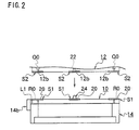
- the sides of base 10 corresponding to edge locators 14b of pallet 14 have distance adjusting side plates L0 and L1, respectively.
- Distance adjusting side plates L0 and L1 abut corresponding edge locators 14b of pallet 14.
- a mount surface 10a of base 10 includes tapered projections 24 at various locations.
- the bottom surface of fixture 12 includes tapered pits 22 corresponding to tapered projections 24 of base 10.
- Distance adjusting side plates L0 and L1 are sized to achieve exact predetermined distances between the inner surfaces of edge locators 14b and tapered projections 24. According to this embodiment, distance adjusting side plates L0 and L1 screw onto the sides of base 10. Thus, exact predetermined distances between the inner surfaces of edge locators 14b and tapered projections 24 is achieved.
- Pallet 14 has a mount groove 14f on its bottom side for fixing pallet 14 to a table or a machining apparatus (or a machine tool).
- Base 10 has projecting contact surfaces 20 projecting from a mount surface 10a of base 10, as shown in Figs. 1-3.
- Fixture 12 also has projecting contact surfaces 12b projecting from the bottom surface of fixture 12. Projecting contact surfaces 12b abut projecting contact surfaces 20 of base 10.
- Tapered projections 24 (see Figs. 2 and 3) that fit in tapered pits 22 respectively provided on the bottom surface of fixture 12 when fixture 12 is mounted on base 10.
- Each tapered projection 24 has a sectionally tapered shape and becomes narrower toward its free end.
- Each tapered pit 22 also has a sectionally tapered shape and becomes narrower toward its inside end.
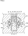
- Tapered projections 24, projecting contact surfaces 20, and base 10 are separate members that have been individually formed and then assembled as shown in Fig. 3.
- Base 10 includes a base body 10b having a plate-like shape, plate members S1 mount on base body 10b further include projected contact surfaces 20. Plate members S1 further include holes P1 extending through plate members S1 in the direction of the height of plate member S1 from mount surface 10a of base 10.
- Plate member S1 also includes a plurality of mounting holes P2 (four mounting holes according to this embodiment as shown in Fig. 1) that surround hole P1 respectively.
- Fig. 1 shows that base body 10b carries six plate members S1. Four plate members S1 are located at the comers, and two other plate members S1 are located in the middle of both side portions. However, the number and arrangement of plate members S1 may be changed according to operational requirements. Base 10 may also be used without projecting contact surfaces 20 which are included on plate members S1, if fixture 12 can be properly placed on base 10 in any other manner.
- base body 10b includes pits T1 on mount surface 10a.
- Pits T1 house tapered projections 24, corresponding to mount positions of holes P1 of plate members S1.
- Pits T1 are formed in the mount positions for plate members S1 generally in the middle of both side portions of base body 10b.
- Each pit T1 is surrounded by a plurality (four in Fig. 1) of female screw holes M1.
- Female screw holes M1 are best shown in Fig. 3.
- Each pit T1 concentrically aligns with hole P1 of plate member S1 when plate member S1 is mounted on base body 10b.
- Each female screw hole M1 concentrically aligns with a corresponding mounting hole P2 of plate members S1 respectively.
- Plate members S1 are held onto base body 10b by screwing flush screws Z1 into female screw holes M1 through respective mount holes P2. Projecting contact surfaces 20 corresponding to pits T1 are therefore fixed to base body 10b.
- a tapered pin G0 forms a tapered projection 24 when inserted into pit T1.
- Tapered pin G0 inserts through hole P1 of plate member S1.
- An adhesive K1 applied to the inner surfaces of pit T1 fixes tapered pin G0 to base body 10b.
- pits T1 may be inserted into base body 10b independent or apart from plate members S1.
- bolt-receiving bolt holes R0 are on the four corners of base body 10b.
- Four plate members S1 are mounted on base body 10b, concentrically aligned with bolt holes R0 respectively.
- Bolt holes R0 also correspond to bolt insert holes Q0 on four corners of fixture 12 respectively.
- Fixture 12 is fixed to base body 10b by inserting bolts (not shown) through bolt insert holes Q0 respectively and threading the bolts through bolt holes R0.
- Each bolt hole R0 opens on mount surface 10a of base body 10b.
- Each bolt hole R0 is surrounded by four female screw holes for mounting plate member S1 similar to screw holes M1 (shown in Fig. 3).
- the four female screw holes also have openings on the top of base body 10b.
- plate members S1 are fixed to base body 10b by screwing flush screws similar to flush screws Z1 into screw holes through mount holes P2 of plate members S1. Projecting contact surfaces 20 corresponding to bolt holes R0 are thus provided on base body 10b.
- Base body 10b, tapered projections 24 and projecting contact surfaces 20 are separate parts according to this embodiment because a separate-part assembly method is easier than cutting and grinding the resultant shape from one solid piece of material.
- Tapered projections 24 are adjacent to projecting contact surfaces 20 on mount surface 10a according to this embodiment. Tapered projections 24 and projecting contact surfaces 20 can be easily cleaned simultaneously, thus reducing the labor required for cleaning a conventional base and fixture.
- tapered projections 24 may be mounted without projecting contact surfaces 20.
- tapered projections 24 and plate members S1 having projecting contact surfaces 20 may be formed as one piece.
- tapered projection 24 and/or projecting contact surface 20 may be constructed with base body 10b as one piece.
- Base body 10b further includes a plurality of holes 20a that are formed between projecting contact surfaces 20. Holes 20a receive fastening bolts (not shown) to be fastened to the T-slot nuts that are inserted in appropriate T-slots 14a. Base 10 is affixed to the top of pallet 14 by bolts inserted holes 20a of base body 10b from above and fastened to the T-slot nuts held in T-slots 14a under base body 10b.
- Projecting contact surfaces 12b abut corresponding projecting contact surfaces 20 of base 10. Therefore, when fixture 12 is affixed to base 10, fixture 12 and base 10 directly contact each other only by projecting contact surfaces 12b and 20.
- the small contact area between projecting contact surfaces 12b and 20 requires that projecting contact surfaces 12b and 20 be perfectly formed to achieve stable and proper contact between them.
- Projected contact surfaces 20 and 12b also facilitate the cleaning operation required prior to mounting fixture 12 to base 10.
- the stable and proper contact between the two members free from intervention of cutting chips or other debris is achieved simply by cleaning projecting contact surfaces 20 and 12b.
- Fixture 12 is thus be firmly affixed to base 10. It is not necessary that projecting contact surface 12b and 20 both be present to achieve the desired results.
- Projecting contact surfaces 12b may be omitted from the bottom surface of fixture 12 (for example, an entirely flat bottom surface of fixture 12 may be employed). Because the debris from a previous machining operation will tend to fall onto base 10, only projecting contact surfaces 20 of base 10 need to be cleaned to achieve proper contact with fixture 12.
- Fixture 12 has plate members S2 on its bottom, as shown in Figs. 1-3. Plate members S2 have projecting contact surfaces 12b. Each plate member S2 has a hole P3 bored through plate member S2 in the direction of the height of plate member S2 from the bottom surface of fixture 12. Plate member S2 also includes a plurality of mount holes P4 (four mount holes according to this embodiment) that surround holes P3. Six of plate members S2 are mounted on fixture 12, at positions corresponding to six plate members S1 provided on base body 10b.
- Fixture 12 includes pits T2 for housing tapered pits 22.
- Pits T2 correspond to the mounting positions for plate members S2.
- the mounting positions correspond to tapered projections 24 on base 10.
- Each pit T2 is surrounded by four screw holes M2.
- Each pit T2 concentrically aligns with hole P3 of plate member S2 when plate member S2 is mounted.
- Screw holes M2 concentrically align with mount holes P4 of plate members S2.
- Plate members S2 are affixed to fixture 12 by inserting flush screws Z2 through mount holes P4 and threading flush screws Z2 into screw holes M2.
- Projecting contact surfaces 12b corresponding to pits T2 are on a bottom surface of fixture 12.
- Taper bushes B0 for forming taper pits 22 insert into respective pits T2 through holes P3 of plate members S2.
- An adhesive K2 applied to the inner surfaces of pit T2 fixes taper bush to base body 10b.
- a lid Y0 closes the end of hole P3 to form pit T2.
- Bolt insert holes Q0 concentrically align with holes P3 of plate members S2 and also with bolt holes R0 of base 10 when fixture 12 is attached to base 10. As described above, bolt insert holes Q0 receive the bolts (not shown) to affix fixture 12 to base 10.
- Each bolt insert hole Q0 opens to the bottom surface of fixture 12.
- Each bolt insert hole Q0 is surrounded by a plurality of (four) screw holes for mounting plate member S2 similar to female screw holes M1 shown in Fig. 3.
- the screw holes also have openings in the bottom surface of fixture 12.
- plate members S2 are affixed to fixture 12 by inserting flush screws similar to flush screws Z2 through mount holes P4 of plate members S2 and threading the flush screws into the screw holes.
- Projecting contact surfaces 12b corresponding to bolt insert holes Q0 are on a bottom surface of fixture 12.
- the fixture 12, tapered bushes B0, and projecting contact surfaces 12b are separate parts according to this embodiment because a separate-part assembly method is easier than cutting and grinding the resultant shape from one solid piece of material. Since tapered pits 22 are adjacent to projecting contact surfaces 12b according to this embodiment, tapered pits 22 and projecting contact surfaces 12b can be easily cleaned, thus reducing the labor required for cleaning the conventional fixture.
- tapered pits 22 may be connected apart from projecting contact surfaces 12b.
- tapered pit 22 and projecting contact surface 12b may be formed as one piece.
- tapered pit 22 and/or a projecting contact surface 12b may be constructed with fixture 12 as one body.
- tapered projections 24 of base 10 fit in tapered pits 22 on the bottom surface of fixture 12. Tapered surfaces of tapered projections 24 abut the tapered surfaces of tapered pits 22 to precisely position fixture 12 relative to base 10.
- tapered projection 24 it is not necessary for tapered projection 24 to completely fill the entire area of tapered pit 22.
- the end of tapered projection 24 may be apart from the blind end of mating tapered pit 22, thus leaving a gap A1 therebetween, as shown in Fig. 3.
- Tapered projections 24 and tapered pits 22 may be formed in other manners, as long as their tapered surfaces abut each other to achieve precision positioning of fixture 12.
- Pallet 14 is fixed to a machining apparatus (or a machine tool) using mount groove 14f.
- mount groove 14f By abutting distance adjusting side plates L0 and L1, which are fixed to the neighboring sides of base 10, to the inside surfaces of edge locators 14b of pallet 14, and screwing bolts into screw holes N1 of base 10 via holes 14c of edge locators 14b, base 10 is positioned and retained to pallet 14.
- Fastening bolts insert through holes 20a of base 10 and thread into T-slot nuts in T-slots 14a to firmly affix base 10 to pallet 14. Once base 10 is fixed to the top surface of pallet 14, there normally is no need to detach base 10 from the top surface of pallet 14.
- Fixture 12 is mounted on mount surface 10a of base 10 so that tapered projections 24 of base 10 fit into tapered pits 22 on the bottom surface of fixture 12.
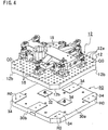
- Jigs 16 may be affixed to fixture 12 after fixture 12 is affixed to base 10.
- a workpiece 18 is fixed to fixture 12 using jigs 16.
- Jigs 16 can be used to affix workpiece 18 to fixture 12 before fixture 12 is mounted on base 10, reducing the setup time required for changing fixtures 12. Such a preparatory setup improves the operation rate of the machining apparatus (or the machine tool).
- a second embodiment of the present invention is shown with portions corresponding to the first embodiment denoted by the same reference numerals.
- the second embodiment includes a base 30 with a mount surface 30a and a base body 30b.
- Mount surface 30a further includes projecting contact surfaces 34.
- Tapered projections 32 which have a sectional tapering shape and become narrower toward their free ends, project from projecting contact surfaces 34 in a relatively central portion of mount surface 30a of base 30.
- Fixture 12 has projecting contact surfaces 12b projecting from the bottom surface thereof for abutting projecting contact surfaces 34 of base 30, as in the first embodiment.
- the bottom of fixture 12 also has tapered pits for fitting over tapered projections 32 of base 30.
- Tapered projections 32 are formed separately from base 30 and are affixed to base 30.
- base 30 includes pits T1 bored into mount surface 30a of base 30.
- Pits T1 house tapered projections 32.
- Adhesive K1 holds taper pins G0 (see Fig. 3), which insert into each pit T1. Tapered projections 32 are thus affixed onto mount surface 30a of base body 30b.
- Fixture 12 has pits T2 bored into a bottom surface of fixture 12.
- Adhesive K2 holds tapered bushes B0 (see Fig. 3), which insert into each pit T2. Tapered pits 22 are thus formed in the bottom surface of fixture 12.
- the third embodiment includes a base 40 having a base body 40b with two side portions 40a on opposing sides of base body 40b.
- Three parallel projecting contact surfaces 44 extend across base body 40b.
- Two projecting contact surfaces 44 extend along side portions 40a respectively.
- the third projecting contact surface 44 extends along a central portion of base body 40b between side portions 40a.
- a plurality of tapered projections 42 having a sectional tapering shape and becoming narrower toward their free ends, are located on either side of the central portion of base body 40b, close to side portions 40a of a base 40.
- Two tapered projections 42 are located relatively close to the central portions of two projecting contact surfaces 44 extending along opposite side portions 40a, respectively.
- fixture 12 As in the first embodiment, fixture 12 (see Fig. 7) includes projecting contact surfaces on its bottom surface that abut projecting contact surfaces 44 of base 40. Tapered pits 45, becoming narrower toward a blind end so that tapered pit 45 fits over corresponding tapered projection 42, engage tapered projections 42 when fixture 12 is affixed to base 40.
- Base 40 further includes grooves 46 on its bottom surface.
- Grooves 46 extend along the bottom surface of base 40 beneath projecting contact surfaces 44 along both side portions 40a. Grooves 46 extend parallel to projecting contact surfaces 44, as shown in Figs. 5 and 6.
- An outer edge of each side portion 40a includes a plurality of elongated openings 50 that open to corresponding groove 46 and to the outer edge. Elongated openings 50 receive fastening bolts 48 from the side.
- Fastening bolts 48 thread into fixture 12 (not shown) from the bottom surface of base 40 to fasten fixture 12 to mount surface 41 of base 40. Without grooves 46 or elongated openings 50, fastening bolts 48 would have to be inserted into openings 50 before pallet 14 connects to the bottom of base 40. Grooves 46 and elongated openings 50 eliminate this problem by allowing insertion of fastening bolts 48 (see Figs. 6, 7) into elongated openings 50 from the side after pallet 14 connects to base 40.
- Each side portion 40a of base 40 includes a plurality of mount holes 54.
- Mount holes 54 receive bolts (not shown) from above, as shown in Fig. 5.
- Mount holes 54 affix fixture 12 to base 40.
- a plurality of holes 56 are bored in base 40, close to both side portions 40a of base 40 for mounting base 40 onto pallet 14.
- base 40 affixes to the top of pallet 14 by inserting bolts (not shown) through holes 56 and threading the bolts into T-slot nuts which are held in T-slots 14a of pallet 14.
- Fixture 12 according to the first embodiment is of plate type.
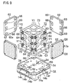
- a fixture 59 of a two-sided block type affixes to a base 58 according to the fourth embodiment.
- Base 58 includes a base body 58b with a mount surface 58a. Projecting contact surfaces 20 on mount surface 58a abut projecting contact surfaces 12b on the bottom of fixture 59. Tapered projections 24 fit into tapered pits 22 in the bottom of fixture 59. Each tapered pit 22 has a sectional tapering shape and becomes narrower toward its blind end. Each tapered projection 24 also has a sectional tapering shape and become narrower toward its free end.
- Base body 58b of base 58 includes a screw hole R1 at each of four comers of base body 58b. Screw holes R1 are used to affix fixture 59 to base 58. Bolt holes R0 are used to affix fixture 12 to base body 58. Alternatively, screw holes may be designed so that they can be used for both fixture 12 (of the plate type) and fixture 59 (of the two-sided block type).
- Fixture 59 includes a fixture body 60 having two opposing mount surfaces Y1.
- Two plates 62 each include a reverse side Y2 facing corresponding mount surface Y1 when plate 62 is affixed to fixture body 60.
- Projecting contact surfaces 65 on each mount surface Y1 abut a contact surface of reverse side Y2 of each plate 62.
- Tapered projections 64 fit into tapered pits 63 bored into reverse side Y2 of each plate 62.
- Each tapered pit 63 has a sectional tapered shape and becomes narrower toward its blind end.
- Each tapered projection 64 also has a sectional tapered shape and becomes narrower toward its free end.
- Projecting contact surfaces 66 on reverse side Y2 of each plate 62 abut projecting contact surfaces 65 of fixture body 60. Thereby, when plate 62 is fixed to fixture body 60, plate 62 and fixture body 60 contact each other only at projecting contact surfaces 66 and 65. This reduced contact area requires precise cutting and grinding of the projecting contact surfaces 65 and 66 to level the contact surfaces and achieve stable and proper contact therebetween.
- the contour of plates 62 and fixture body 60 is precisely defined such that projecting contact surfaces 66 of plates 62 contact only projecting contact surfaces 65 of fixture body 60. Projecting contact surfaces 65 and 66 facilitate the cleaning operation required prior to mounting plates 62 to fixture body 60. The stable and proper contact between plates 62 to fixture body 60, free from intervention of cutting chips or debris, can be achieved simply by cleaning projecting contact surfaces 65 and 66.
- reverse side Y2 of each plate 62 may be entirely flat. That is, projecting contact surfaces 66 may be omitted from reverse side Y2 of each plate 62 without departing from the spirit and scope of this invention.
- Bolt insert holes Ql receive bolts (not shown).
- Bolt insert holes Q1 correspond to screw holes Rl of base 58.
- Fixture body 60 additionally includes a base U0.
- Base U0 includes projections 70 below the area where plates 62 mount onto mount surfaces Y1. During mounting of plates 62 on mount surfaces Y1 of fixture body 60, lower ends 62a of plates 62 may be set on projections 70 on base U0 of fixture body 60.
- plates 62 can be detached from fixture body 60 at first and a workpiece 18 and jigs 16 (see Figs. 1, 4) affixed to plates 62, prior to mounting of plates 62 to fixture body 60.
- Jigs 16 affix workpiece 18 to fixture 12 before fixture 12 is mounted on base 10, reducing the setup time required for changing fixtures 12.
- Such a preparatory setup improves the operating rate of the machining apparatus (or the machine tool).
- Plates 62 can also be fixed directly to mount surface 58a of base 58 to use it as a plate type fixture. However, such construction is optional.
- fixture body 60 and plates 62 of fixture 59 are shown as separate members according to Fig. 8, fixture body 60 and plates 62 may be manufactured from one piece.
- Projecting contact surfaces 65 and/or tapered projections 64 may be manufactured either separately from fixture body 60 or from one piece with fixture body 60. Similarly, projecting contact surfaces 66 and/or tapered pits 63 may be manufactured separately from plate 62 or from one piece with plates 62.
- a fixture 72 is a four-sided block having mount surfaces Y1 on each of four sides.
- a fixture body 73 of fixture 72 has base U0 at its bottom, as in the fourth embodiment described above.
- Base U0 has in its bottom surface projecting contact surfaces 12b and taper pits 22.
- Each of tapered pits 22 has a sectional tapering shape and becomes narrower toward its blind end (see Fig. 8).
- a base 74 has a mount surface 74a.
- Mount surface 74a includes projecting contact surfaces 34 formed together with a base body 74b of base 74, as in the second embodiment.
- Tapered projections 32 are formed separately from base body 74b and affixed thereto. Tapered projections 32 have a sectional tapered shape and become narrower toward their free end.
- Fixture 72 further includes four plates 62 which fixedly attach to fixture body 73.
- Each plate 62 has a reverse side Y2 facing corresponding mount surface Y1 of fixture body 73 when plate 62 is fixed to fixture body 73.
- each mount surface Y1 includes projecting contact surfaces 65 abutting a contact surface of reverse side Y2 of each plate 62.
- tapered projections 64 fit into tapered pits 63 on reverse side Y2 of each plate 62.
- Each tapered pit 63 has a sectional tapered shape and becomes narrower toward its blind end.
- Projecting contact surfaces 66 on reverse side Y2 of each plate 62 abut projecting contact surfaces 65 of fixture body 73, such that direct contact between plate 62 and fixture body 73 occurs only at projecting contact surfaces 65 and 66 thereof.
- tapered projections 64 and projecting contact surfaces 66 are separate and distinct pieces from fixture bodies 60 and 73.
- Each mount surface Y1 of fixture bodies 60 and 73 has pits for tapered projections 64.
- Tapered pins G0 housed in pits form tapered projections 64.
- Adhesive K1 affixes tapered pins G0 into the pits.
- Reverse side Y2 of each plate 62 also has pits for housing tapered pits 63.
- Tapered bushes B0 insert into the pits to form tapered pits 63.
- Adhesive K2 affixes tapered bushes B0 into the pits.
- the plate type fixture may have a shape of a disc, or other shape.
- the fixture may be of a type other than the plate, the two-sided block or the four-sided block. It could be a triangular type, a pyramid type or any other shaped fixture that can be used to hold a workpiece on a base.
- reference holes of the fixture may be located in predetermined locations instead of the matrix arrangement over the entire surface as shown in the figures.
- the reference holes may be replaced by reference slots having a sectional shape of, for example, a letter T.
- the reference holes or slots may be entirely omitted from the fixture.
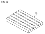
- the base of the present invention can be fixed to a device other than pallet 14 of a machine tool.
- the base may be fixed to a table D1 of a machine tool as shown in Fig. 10.
- tapered pins G0 forming tapered projections 24 and/or tapered bushes B0 forming tapered pits 22, as described in connection with the first embodiment may be fixed in respective pits, T1 and T2, using various methods other than the use of adhesives K1 and K2.
- tapered pins G0 and tapered bushes B0 may be threaded in pits T1 and T2.
- Such various fixing methods may also be used to form tapered projections 32, 42, and 64 and tapered pits 63 described in connection with all other embodiments.
Landscapes
- Engineering & Computer Science (AREA)
- Mechanical Engineering (AREA)
- Jigs For Machine Tools (AREA)
- Supply And Installment Of Electrical Components (AREA)
- Connection Of Plates (AREA)
Claims (17)
- Bearbeitungsvorrichtung, umfassend:wobei Vorsprünge (24, 32) auf der Halterungs- bzw. Aufspannoberfläche (10a, 30a, 58a, 74a) und Vertiefungen (22), um darin die Vorsprünge aufzunehmen, auf der Unterseite angeordnet sind, um die Grundplatte (10, 30, 58, 74) und die Halte- bzw. Spannvorrichtung (12, 59, 72) miteinander auszurichten;eine Grundplatte (10, 30, 58, 74) mit einer Halterungs- bzw. Aufspannoberfläche (10a, 30a, 58a, 74a);eine Halte- bzw. Spannvorrichtung (12, 59, 72), um ein Werkstück (18) mit einer Unterseite zu halten;Mittel (48), um die Halte- bzw. Spannvorrichtung (12, 59, 72) an der Grundplatte (10, 30, 58, 74) zu befestigen;wobei die Halterungs- bzw. Aufspannoberfläche (10a, 30a, 58a, 74a) eine Mehrzahl von diskreten ersten Kontaktoberflächen (20, 34) aufweist, die von der Halterungs- bzw. Aufspannoberfläche vorstehen;wobei die Unterseite eine Mehrzahl von diskreten zweiten Kontaktoberflächen (12b) aufweist, die von der Unterseite vorstehen;wobei die ersten und zweiten vorstehenden Oberflächen aneinander anliegen, wenn die Halte- bzw. Spannvorrichtung (12, 59, 72) an der Grundplatte (10, 30, 58, 74) befestigt ist;
dadurch gekennzeichnet, dass die Vorsprünge (24, 32) jeweils von einer ersten Kontaktoberfläche (20, 34) vorstehen und dass die Vertiefungen (22) jeweils in einer zweiten Kontaktoberfläche (12b) ausgebildet sind, wobei die Vorsprünge fest an der Grundplatte angebracht sind oder einstückig mit der Grundplatte ausgebildet sind. - Bearbeitungsvorrichtung nach Anspruch 1, bei der die ersten Kontaktoberflächen (20, 34) integraler Bestandteil der Grundplatte (10, 30, 58, 74) sind.
- Bearbeitungsvorrichtung nach Anspruch 1, bei der die Vorsprünge (24, 32) separat und verschieden zu der Grundplatte sind und fest an der Grundplatte angebracht bzw. befestigt sind.
- Bearbeitungsvorrichtung nach einem der Ansprüche 1 bis 3, bei der:die Vorsprünge (24, 32) kegelstumpfförmig sind, so dass die Vorsprünge zu deren freiem Ende hin schmäler sind;die Vertiefungen (22) kegelstumpfförmig sind, so dass die Vertiefungen zu deren blindem Ende hin schmäler sind; unddie Vorsprünge fest bzw. eng anliegend in die Vertiefungen passen, so dass die Grundplatte und die Halte- bzw. Spannvorrichtung präzise ausgerichtet sind.
- Bearbeitungsvorrichtung nach Anspruch 4, bei der:die kegelstumpfförmigen Vorsprünge (24, 32) einen kegelstumpfförmigen Zapfen (G0) aufweisen, der in eine erste Vertiefung (T1), die in die Halterungs- bzw. Aufspannoberfläche der Grundplatte gebohrt ist, eingeführt und befestigt ist; unddie kegelstumpfförmigen Vertiefungen (22) eine kegelstumpfförmige Buchse (B0) aufweisen, die in eine zweite Vertiefung (T2), die in die Unterseite der Halte- bzw. Spannvorrichtung gebohrt ist, eingesetzt und befestigt ist.
- Bearbeitungsvorrichtung nach einem der vorhergehenden Ansprüche, bei der die zweiten Kontaktoberflächen (12b) integraler Bestandteil der Halte- bzw. Spannvorrichtung sind.
- Bearbeitungsvorrichtung nach einem der vorhergehenden Ansprüche, bei der die Halte- bzw. Spannvorrichtung eine planare bzw. flächige Halterungs- bzw. Aufspannvorrichtung oder einen doppelseitigen Block oder einen vierseitigen Block aufweist.
- Bearbeitungsvorrichtung nach einem der vorhergehenden Ansprüche, bei der:die Halte- bzw. Spannvorrichtung zumindest eine separate Halterungs- bzw. Aufspannvorrichtung aufweist, die an einer Vorrichtungs-Halterungsoberfläche (Y1) der Halte- bzw. Spannvorrichtung anbringbar ist, sowie diskrete dritte Kontaktoberflächen; unddie zumindest eine separate Halterungs- bzw. Aufspannvorrichtung die Vorrichtungs-Halterungsoberfläche (Y1) der Halte- bzw. Spannvorrichtung nur bei der dritten Kontaktoberfläche berührt.
- Bearbeitungsvorrichtung nach Anspruch 8, bei der die zumindest eine separate Halterungs- bzw. Aufspannvorrichtung vierte Kontaktoberflächen aufweist, welche den dritten Kontaktoberflächen entsprechen, so dass die zumindest eine separate Halterungs- bzw. Aufspannvorrichtung und die Vorrichtungs-Halterungsoberfläche (Y1) der Halte- bzw. Spannvorrichtung einander bei den dritten und vierten Kontaktoberfläche berühren.
- Bearbeitungsvorrichtung nach Anspruch 9, bei der die Halte- bzw. Spannvorrichtung und die zumindest eine separate Halterungs- bzw. Aufspannvorrichtung ein zweites Mittel aufweisen, um die zumindest eine separate Halterungs- bzw. Aufspannvorrichtung auf der Vorrichtungs-Halterungsoberfläche (Y1) der Halte- bzw. Spannvorrichtung auszurichten.
- Bearbeitungsvorrichtung nach Anspruch 10, bei der die Halte- bzw. Spannvorrichtung und die Grundplatte ein erstes Mittel aufweisen, um die Halte- bzw. Spannvorrichtung auf der Grundplatte auszurichten.
- Bearbeitungsvorrichtung nach Anspruch 11, bei der die ersten und zweiten Mittel zum Ausrichten zweite Vorsprünge auf der Grundplatte und der Halte- bzw. Spannvorrichtung aufweisen, die zweiten Vertiefungen auf der Halte- bzw. Spannvorrichtung bzw. der zumindest einen separaten Halterungs- bzw. Aufspannvorrichtung entsprechen.
- Bearbeitungsvorrichtung nach Anspruch 12, bei der die ersten und zweiten Kontaktoberflächen integrale Bestandteile der Grundplatte sind.
- Bearbeitungsvorrichtung nach Anspruch 12, bei der die dritten und vierten Kontaktoberflächen und die zweiten Vorsprünge separat und verschieden Zu der Grundplatte, der Halte- bzw. Spannvorrichtung und der zumindest einen separaten Halterungs- bzw. Aufspannvorrichtung sind und fest an der Grundplatte, der Halte- bzw. Spannvorrichtung und der zumindest einen separaten Halterungs- bzw. Aufspannvorrichtung angebracht bzw. befestigt sind.
- Bearbeitungsvorrichtung nach Anspruch 12, bei der:die zweiten Vorsprünge kegelstumpfförmig sind, so dass die zweiten Vorsprünge zu deren freiem Ende hin schmäler sind;die zweiten Vertiefungen kegelstumpfförmig sind, so dass die zweiten Vertiefungen zu deren blindem Ende hin schmäler sind; unddie zweiten Vorsprünge eng anliegend in die zweiten Vertiefungen passen, so dass die Halte- bzw. Spannvorrichtung und die zumindest eine separate Halterungs- bzw. Aufspannvorrichtung präzise ausgerichtet sind.
- Grundplatte (10, 30, 58, 74) mit einer Halterungs- bzw. Aufspannoberfläche (10a, 30a, 58a, 74a), um eine Halte- bzw. Spannvorrichtung (12, 59, 72) zum Halten bzw. Aufspannen eines Werkstücks (18) auf der Halterungs- bzw. Aufspannoberfläche fest anzubringen bzw. auf dieser zu befestigen, umfassend:dadurch gekennzeichnet, dass die Vorsprünge (24, 32) jeweils von einer ersten Kontaktoberfläche (20, 34) vorstehen und fest an der Grundplatte angebracht sind oder einstückig bzw. integral mit der Grundplatte ausgebildet sind.diskrete erste Kontaktoberflächen (20, 34), die von der Halterungs- bzw. Aufspannoberfläche vorstehen, zur Anlage an den zweiten Kontaktoberflächen (12b), die von einer Unterseite der Halte- bzw. Spannvorrichtung (12, 59, 72) vorstehen, wenn die Halte- bzw. Spannvorrichtung (12, 59, 72) fest an der Grundplatte (10, 30, 58, 74) angebracht ist; undVorsprünge (24, 32), um in Aufnahmevertiefungen (22), die auf der Unterseite angeordnet sind, eingeführt zu werden, zur gegenseitigen Ausrichtung der Grundplatte (10, 30, 58, 74) und der Halte- bzw. Spannvorrichtung (12, 59, 72);
- Halte- bzw. Spannvorrichtung (12, 59, 72), um ein Werkstück zu halten bzw. aufzuspannen, das fest an einer Grundplatte (10, 30, 58, 74) mit einer Halterungs- bzw. Aufspannoberfläche (10a, 30a, 58a, 74a) anbringbar ist, wobei die Halte- bzw. Spannvorrichtung eine Unterseite aufweist und umfasst:dadurch gekennzeichnet, dass die Vertiefungen (22) jeweils in einer zweiten Kontaktoberfläche (12b) ausgebildet sind.diskrete zweite Kontaktoberflächen (12b), die von der Unterseite vorstehen, zur Anlage an ersten Kontaktoberflächen (20, 34), die von der Halterungs- bzw. Aufspannoberfläche vorstehen, wenn die Halte- bzw. Spannvorrichtung (12, 59, 72) fest an der Grundplatte (10, 30, 58, 74) angebracht ist; undVertiefungen (22), um darin Vorsprünge aufzunehmen, die auf der Halterungs- bzw. Aufspannoberfläche angeordnet sind, um die Grundplatte (10, 30, 58, 74) und die Halte- bzw. Spannvorrichtung (12, 59, 72) miteinander auszurichten;
Applications Claiming Priority (3)
| Application Number | Priority Date | Filing Date | Title |
|---|---|---|---|
| JP6282977A JPH08118175A (ja) | 1994-10-21 | 1994-10-21 | 取付用ベース部材及びそのベース部材に取り付けられる取付具 |
| JP282977/94 | 1994-10-21 | ||
| JP28297794 | 1994-10-21 |
Publications (2)
| Publication Number | Publication Date |
|---|---|
| EP0712684A1 EP0712684A1 (de) | 1996-05-22 |
| EP0712684B1 true EP0712684B1 (de) | 2003-12-17 |
Family
ID=17659599
Family Applications (1)
| Application Number | Title | Priority Date | Filing Date |
|---|---|---|---|
| EP95116556A Expired - Lifetime EP0712684B1 (de) | 1994-10-21 | 1995-10-20 | Träger und Spannvorrichtung für Bearbeitungsvorgänge |
Country Status (7)
| Country | Link |
|---|---|
| US (1) | US5788225A (de) |
| EP (1) | EP0712684B1 (de) |
| JP (1) | JPH08118175A (de) |
| KR (1) | KR100196474B1 (de) |
| CN (1) | CN1076245C (de) |
| DE (1) | DE69532319T2 (de) |
| TW (1) | TW358054B (de) |
Families Citing this family (74)
| Publication number | Priority date | Publication date | Assignee | Title |
|---|---|---|---|---|
| JP3377351B2 (ja) * | 1995-12-18 | 2003-02-17 | 松下電器産業株式会社 | 電子部品実装機 |
| DE19826328C1 (de) * | 1997-09-03 | 1999-11-25 | Hohenstein Vorrichtungsbau | Schnell-Paß-System für Bauteile von Werkzeugmaschinen |
| JP3646850B2 (ja) * | 1998-08-06 | 2005-05-11 | 本田技研工業株式会社 | マシニングセンタの加工物マガジン |
| US6206357B1 (en) * | 1998-11-02 | 2001-03-27 | Douglas J. Peck | Kit of interchangeable workpiece locating and holding elements |
| DE19943605C2 (de) * | 1999-09-11 | 2002-06-20 | Hohenstein Vorrichtungsbau | Adaptive Werkstückspannvorrichtung |
| US6252192B1 (en) * | 2000-01-18 | 2001-06-26 | Precision Die & Machine Company | EDM tool holder |
| US6509753B2 (en) * | 2000-02-23 | 2003-01-21 | Agilent Technologies, Inc. | Customizable nest that requires no machining or tools |
| US6752391B1 (en) * | 2000-02-23 | 2004-06-22 | Agilent Technologies, Inc. | Customizable nest with the option of conversion to a permanent nest |
| IT1321175B1 (it) * | 2000-04-20 | 2003-12-30 | Pierre S N C | Impostatore - trasportatore su linea dei componenti meccanici daassemblare nelle lavorazioni automatiche . |
| WO2002020374A2 (en) * | 2000-09-05 | 2002-03-14 | Montague Tool & Manufacturing Co. | Versatile palletized work holding system |
| US6511574B2 (en) | 2001-01-18 | 2003-01-28 | International Business Machines Corporation | Fixture for securing hard stops to a substrate |
| EP1260304B1 (de) * | 2001-05-25 | 2004-11-17 | Cross Hüller GmbH | Werkstückhalter |
| US6711796B2 (en) * | 2001-10-11 | 2004-03-30 | Anderson Industrial Corp. | Circuit board stripper |
| US6644641B2 (en) | 2002-02-06 | 2003-11-11 | Randy Phillips | Interchangeable locating pin assembly for locating manufactured parts |
| DE10214328A1 (de) * | 2002-03-28 | 2003-10-16 | Thomas Herbert Drittenpreis | Vorrichtung für die Aufnahme von zu bearbeitenden Werkstücken |
| US6768076B2 (en) * | 2002-05-15 | 2004-07-27 | Joseph M. Walter | Precision base and fixture adapter set-up |
| US6918577B2 (en) * | 2002-09-24 | 2005-07-19 | Ford Motor Company | Tooling plate for a flexible manufacturing system |
| US20040055129A1 (en) * | 2002-09-24 | 2004-03-25 | Abid Ghuman | Method of engineering a flexible process line |
| US7178227B2 (en) | 2002-09-24 | 2007-02-20 | Ford Motor Company | Workpiece presenter for a flexible manufacturing system |
| US20040055147A1 (en) * | 2002-09-24 | 2004-03-25 | Abid Ghuman | Process line for a flexible manufacturing system |
| US20040056069A1 (en) * | 2002-09-24 | 2004-03-25 | Abid Ghuman | Method of engineering a process line for a flexible manufacturing system |
| US6899377B2 (en) * | 2002-09-24 | 2005-05-31 | Ford Motor Company | Vehicle body |
| US20040055131A1 (en) * | 2002-09-24 | 2004-03-25 | Abid Ghuman | Method of assembling vehicles in a flexible manufacturing system |
| US20040056497A1 (en) * | 2002-09-24 | 2004-03-25 | Abid Ghuman | Flexible manufacturing system |
| US20040124573A1 (en) * | 2002-12-30 | 2004-07-01 | Elman Larisa Alexandra | Modular metalworking tooling apparatus |
| US6993821B2 (en) * | 2002-12-30 | 2006-02-07 | General Electric Company | Manufacturing cell using tooling apparatus |
| US7083166B1 (en) * | 2003-10-01 | 2006-08-01 | Durfee David L | Light-weight, modular work-holding chassis |
| JP4326982B2 (ja) * | 2004-02-18 | 2009-09-09 | ヤマザキマザック株式会社 | 加工治具 |
| US20050223532A1 (en) * | 2004-04-08 | 2005-10-13 | Ford Global Technologies, Llc | Method of designing a vehicle closure assembly line |
| US7686553B2 (en) * | 2004-08-27 | 2010-03-30 | Durfee Jr David L | Precision positioning and fastening system |
| WO2006031265A1 (en) * | 2004-09-10 | 2006-03-23 | Delphi Technologies Inc. | Machining fixture assembly and method including an adaptor |
| JP2006142419A (ja) * | 2004-11-17 | 2006-06-08 | Imao Corporation:Kk | 取付補助ベースおよび位置決め部材、並びに、工作機械のパレット |
| DE102005038407A1 (de) * | 2005-08-12 | 2007-02-15 | Ludwig Ehrhardt Gmbh | Spannvorrichtung sowie Verfahren zum Bearbeiten von an einer solchen Spannvorrichtung gespannten Werkstücken |
| US20070097346A1 (en) * | 2005-10-28 | 2007-05-03 | Asml Netherlands B.V. | Lithographic apparatus and device manufacturing method |
| US20070101568A1 (en) * | 2005-11-04 | 2007-05-10 | Doom Michael J | Method for improved fixture design |
| DE102005056449A1 (de) * | 2005-11-26 | 2007-08-02 | Alfing Kessler Sondermaschinen Gmbh | Werkstückhaltevorrichtung und damit ausgestattete Bearbeitungsmaschine |
| DE102006002081A1 (de) * | 2006-01-16 | 2007-07-26 | Robert Bosch Gmbh | Werkstückträger |
| CN101505917B (zh) * | 2006-09-04 | 2012-05-30 | 株式会社牧野铣床制作所 | 机床及随行夹具待机站 |
| US8028976B2 (en) * | 2007-10-15 | 2011-10-04 | Ocenco, Inc. | Machining fixture with self-contained hydraulics |
| FR2933630A1 (fr) * | 2008-07-10 | 2010-01-15 | Renault Sas | Dispositif de fixation manuelle d'un outillage interchangeable et poste de travail comportant un tel dispositif |
| US8292282B2 (en) * | 2008-12-05 | 2012-10-23 | GM Global Technology Operations LLC | Flexible support assembly for vehicle tooling plates |
| US8534658B2 (en) * | 2009-04-03 | 2013-09-17 | Jergens, Inc. | Mounting system |
| WO2011075249A1 (en) * | 2009-12-14 | 2011-06-23 | Alcon, Inc. | Devices and methods for holding an intraocular lens during the processing and packaging of the intraocular lens |
| KR100979539B1 (ko) | 2010-01-29 | 2010-09-02 | 아주대학교산학협력단 | 평면 3자유도 스테이지 |
| DE102010011947A1 (de) * | 2010-02-17 | 2011-08-18 | Illinois Tool Works Inc., Ill. | Anschlusselement zum Ausbilden einer Schnittstelle zwischen zwei lösbar miteinander verbindbaren Teilen einer Werkzeugmaschine sowie Verfahren zum Herstellen eines solchen Anschlusselements |
| CN101758407B (zh) * | 2010-03-03 | 2011-05-18 | 天津市中马骏腾精密机械制造有限公司 | 一种多工序随行工装 |
| JP5572449B2 (ja) * | 2010-06-03 | 2014-08-13 | パスカルエンジニアリング株式会社 | 物体位置決め固定装置 |
| DE102010037546A1 (de) * | 2010-09-15 | 2012-03-15 | Klaus Hofmann | Sicherungs-Spannvorrichtung |
| CN102608772A (zh) * | 2011-01-24 | 2012-07-25 | 深圳富泰宏精密工业有限公司 | 视窗安装治具 |
| CN102328215A (zh) * | 2011-07-14 | 2012-01-25 | 江苏汤臣汽车零部件有限公司 | 一种整体式减速器壳铣端盖连接法兰面工装 |
| CN102490043B (zh) * | 2011-12-19 | 2013-12-11 | 綦江齿轮传动有限公司 | 汽车变速器行星架加工定位的液压镗模 |
| JP5795964B2 (ja) * | 2012-01-26 | 2015-10-14 | 西部電機株式会社 | レベル調整治具を備える板材保持装置と板材の配置調整方法 |
| DE102013109780A1 (de) | 2013-09-06 | 2015-03-12 | Mag Ias Gmbh | Werkstückadaptervorrichtung, Werkstückhaltevorrichtung-Werkstückadaptervorrichtung-Kombination und Werkzeugmaschine |
| CN103722510B (zh) * | 2013-12-27 | 2015-07-08 | 江苏大学 | 一种可拆卸的汽车灯具夹具 |
| EP3102021B1 (de) * | 2014-02-03 | 2020-03-11 | Husqvarna AB | Zum halten eines werkzeugs angepasste plattenfeder, werkzeug, werkzeughalter, robotisches arbeitswerkzeug und ein robotisches arbeitswerkzeugsystem |
| CN104874858B (zh) * | 2014-02-28 | 2018-11-23 | 苏州市昌星模具机械有限公司 | 高效液压拉床 |
| US9441654B2 (en) * | 2014-06-03 | 2016-09-13 | Modern Industries, Inc. | Precision positioning and fastening system |
| FR3026332B1 (fr) * | 2014-09-26 | 2017-04-14 | Aerolia | Dispositif de bridage d'une piece brute a usiner |
| CN104476443A (zh) * | 2014-12-08 | 2015-04-01 | 广西玉柴机器股份有限公司 | 一种气体机的节气门的辅助安装装置 |
| CN105983929B (zh) * | 2015-03-04 | 2018-05-15 | 富鼎电子科技(嘉善)有限公司 | 定位装置 |
| CH711177A1 (fr) * | 2015-06-11 | 2016-12-15 | Watch Out Sa | Système d'usinage de pièces, module de mise au point et procédé d'usinage de pièces. |
| US10022828B2 (en) * | 2015-06-29 | 2018-07-17 | Mai Van Nguyen | Zero-point fixture |
| CN105364540A (zh) * | 2015-11-30 | 2016-03-02 | 苏州源硕精密模具有限公司 | 一种工件支承装置 |
| CN105291047B (zh) * | 2015-12-04 | 2017-03-15 | 广西玉柴机器股份有限公司 | Egr阀上螺栓的辅助安装装置 |
| JP6434463B2 (ja) * | 2016-08-30 | 2018-12-05 | ファナック株式会社 | ワークをクランプするパレット装置、工作機械、および加工システム |
| CN106271748A (zh) * | 2016-09-28 | 2017-01-04 | 广州凯耀资产管理有限公司 | 一种可拆卸机械加工夹具组件及其工作方法 |
| EP3646985A4 (de) * | 2017-11-07 | 2020-11-18 | Mitsubishi Heavy Industries, Ltd. | Verarbeitungsvorrichtung und verarbeitungsverfahren |
| IT201800009670A1 (it) * | 2018-10-22 | 2020-04-22 | Scm Group Spa | Macchina utensile per la lavorazione di pannelli. |
| JP7237715B2 (ja) * | 2019-05-07 | 2023-03-13 | オークマ株式会社 | ワークテーブル |
| KR102146466B1 (ko) * | 2020-05-18 | 2020-08-20 | 터보파워텍(주) | 노즐리테이닝링 변형방지용 가공지그장치 |
| CN115213506B (zh) * | 2021-04-21 | 2025-02-25 | 中核(天津)科技发展有限公司 | 一种盘类零件异形槽加工用装夹具及其使用方法 |
| US12330255B2 (en) | 2022-04-07 | 2025-06-17 | Shelby Supply Co. | Clamping system and method for using same |
| FR3135638B1 (fr) * | 2022-05-17 | 2024-05-31 | Moule Design Prototype | Procédé et installation de fabrication d’une pièce à partir d’un bloc. |
| US12350736B2 (en) * | 2022-07-28 | 2025-07-08 | Mueller International, Llc | Part tree support system |
Family Cites Families (21)
| Publication number | Priority date | Publication date | Assignee | Title |
|---|---|---|---|---|
| AT268825B (de) * | 1967-07-24 | 1969-02-25 | Deckel Ag Friedrich | Klemmvorrichtung für verschiebbare Bauteile von Werkzeugmaschinen |
| FR2523492A1 (fr) * | 1982-03-22 | 1983-09-23 | Renault | Dispositif de positionnement rapide et de bridage, en particulier pour l'usinage de grosses pieces sur un centre d'usinage |
| US4585217A (en) * | 1983-09-20 | 1986-04-29 | Erickson Robert W | Workpiece support apparatus and method |
| US4610020A (en) * | 1984-01-06 | 1986-09-02 | The Perkin-Elmer Corporation | X-ray mask ring and apparatus for making same |
| US4630811A (en) * | 1985-07-16 | 1986-12-23 | Cincinnati Milacron Inc. | Modular fixturing apparatus |
| JPH0645388B2 (ja) * | 1985-07-16 | 1994-06-15 | 株式会社三谷バルブ | ポンプ容器 |
| JPS62157754A (ja) * | 1985-12-27 | 1987-07-13 | Tsudakoma Ind Co Ltd | パレツトクランプ装置 |
| JPS62259727A (ja) * | 1986-05-03 | 1987-11-12 | Nippon Denso Co Ltd | 製品搬送用パレツト |
| US4828240A (en) * | 1986-09-02 | 1989-05-09 | Te-Co. | Workpiece securing apparatus for a machine tool |
| JPS6434627A (en) * | 1987-07-30 | 1989-02-06 | Tsudakoma Ind Co Ltd | Pallet clamp equipment of machine tool |
| DE3729601C1 (de) * | 1987-09-04 | 1988-10-27 | Erowa Ag | Vorrichtung zum Aufspannen eines Werkstueckes oder Werkzeuges |
| ES2030130T3 (es) * | 1987-09-24 | 1992-10-16 | Buchler B-Set Ag | Procedimiento para la fabricacion de una paleta. |
| US5190273A (en) * | 1987-12-10 | 1993-03-02 | Sz S.R.L. | Pallet with adjustable anchorage system for equipping the clamping fixture of a rough piece to be machined with machine tools |
| US4834358A (en) * | 1988-02-04 | 1989-05-30 | Carr Lane Mfg. Co. | Modular fixturing system |
| DE3919077C1 (de) * | 1989-06-10 | 1990-07-26 | Erowa Ag, Reinach, Ch | |
| US5195227A (en) * | 1989-12-13 | 1993-03-23 | The J. L. Wickham Co., Inc. | Quick change mounting system for machine tools |
| JPH04289045A (ja) * | 1990-08-20 | 1992-10-14 | Murata Mach Ltd | パレット設置テーブル |
| US5190272A (en) * | 1990-12-20 | 1993-03-02 | Snow/Taft-Peirce Company | Actuator and palletizing system |
| US5275326A (en) * | 1992-08-21 | 1994-01-04 | Lsi Logic Corporation | Guide hole sleeves for boat transports supporting semiconductor device assemblies |
| DE4307342C2 (de) * | 1993-03-09 | 1994-12-08 | Erowa Ag | Einrichtung zum positionsdefinierten Aufspannen eines Werkstücks am Arbeitsplatz einer Bearbeitungsmaschine |
| DE4314629C2 (de) * | 1993-05-04 | 1995-10-19 | Erowa Ag | Vorrichtung zum positionsdefinierten Aufspannen eines Werkstücks am Arbeitsplatz einer Bearbeitungsmaschine |
-
1994
- 1994-10-21 JP JP6282977A patent/JPH08118175A/ja active Pending
-
1995
- 1995-08-29 TW TW084109004A patent/TW358054B/zh not_active IP Right Cessation
- 1995-10-02 KR KR1019950034084A patent/KR100196474B1/ko not_active Expired - Fee Related
- 1995-10-18 CN CN95118713A patent/CN1076245C/zh not_active Expired - Fee Related
- 1995-10-20 DE DE69532319T patent/DE69532319T2/de not_active Expired - Fee Related
- 1995-10-20 EP EP95116556A patent/EP0712684B1/de not_active Expired - Lifetime
-
1997
- 1997-03-14 US US08/818,385 patent/US5788225A/en not_active Expired - Fee Related
Also Published As
| Publication number | Publication date |
|---|---|
| DE69532319T2 (de) | 2004-06-09 |
| CN1076245C (zh) | 2001-12-19 |
| KR100196474B1 (ko) | 1999-06-15 |
| EP0712684A1 (de) | 1996-05-22 |
| US5788225A (en) | 1998-08-04 |
| DE69532319D1 (de) | 2004-01-29 |
| CN1130117A (zh) | 1996-09-04 |
| KR960013567A (ko) | 1996-05-22 |
| JPH08118175A (ja) | 1996-05-14 |
| TW358054B (en) | 1999-05-11 |
Similar Documents
| Publication | Publication Date | Title |
|---|---|---|
| EP0712684B1 (de) | Träger und Spannvorrichtung für Bearbeitungsvorgänge | |
| KR101488258B1 (ko) | 임플란트용 어버트먼트 가공용 지그 및 이를 이용한 어버트먼트 가공방법 | |
| US5634757A (en) | Fastening device for a tool or workpiece | |
| US4834358A (en) | Modular fixturing system | |
| FI93178B (fi) | Laite työkappaleen kiinnittämiseksi asemaltaan määritellysti työstöpöydälle | |
| GB2344560A (en) | Vibration welding apparatus with removable upper jig | |
| JPS59102576A (ja) | 機械加工用部品締付用の締付クランプ | |
| US4681270A (en) | Manufactured refining element | |
| CA2277402C (en) | A holding device for workpieces in the form of even metal sheets | |
| KR102210680B1 (ko) | 정밀한 길이조절이 가능한 절삭인서트용 공구홀더 | |
| KR20230097821A (ko) | 토크 체결용 지그 | |
| CN118905675A (zh) | 一种异形扩散器大小端安装边加工的夹具及方法 | |
| CN118493015A (zh) | 一种金属零件的连续性加工夹具系统及方法 | |
| CN213135884U (zh) | 一种模具机床 | |
| JP2000005957A (ja) | 工作機械用チャック取付治具 | |
| KR101608041B1 (ko) | 대형 디스크제품 가공보조용 지그장치 | |
| KR200312867Y1 (ko) | 랙가공용지그 | |
| CN218254728U (zh) | 一种方便拆装的z形件夹具工装 | |
| JP3254326U (ja) | コレット内に冷却剤チャネルを形成するための固定具 | |
| JPH0529792Y2 (de) | ||
| JP2944794B2 (ja) | 取付具 | |
| CN213410902U (zh) | 一种柔性组合式焊装夹具 | |
| CN210147576U (zh) | 一种连接板加工治具 | |
| KR200155670Y1 (ko) | 호빙머신의 아버 | |
| JPH1030905A (ja) | 姿見用検査治具 |
Legal Events
| Date | Code | Title | Description |
|---|---|---|---|
| PUAI | Public reference made under article 153(3) epc to a published international application that has entered the european phase |
Free format text: ORIGINAL CODE: 0009012 |
|
| AK | Designated contracting states |
Kind code of ref document: A1 Designated state(s): CH DE IT LI |
|
| 17P | Request for examination filed |
Effective date: 19961009 |
|
| RAP3 | Party data changed (applicant data changed or rights of an application transferred) |
Owner name: KABUSHIKI KAISHA IMAO CORPORATION |
|
| 17Q | First examination report despatched |
Effective date: 20001205 |
|
| GRAP | Despatch of communication of intention to grant a patent |
Free format text: ORIGINAL CODE: EPIDOSNIGR1 |
|
| GRAS | Grant fee paid |
Free format text: ORIGINAL CODE: EPIDOSNIGR3 |
|
| GRAA | (expected) grant |
Free format text: ORIGINAL CODE: 0009210 |
|
| AK | Designated contracting states |
Kind code of ref document: B1 Designated state(s): CH DE IT LI |
|
| REG | Reference to a national code |
Ref country code: CH Ref legal event code: EP |
|
| REG | Reference to a national code |
Ref country code: CH Ref legal event code: NV Representative=s name: ROSENICH PAUL; GISLER CHRISTIAN PATENTBUERO PAUL R |
|
| REF | Corresponds to: |
Ref document number: 69532319 Country of ref document: DE Date of ref document: 20040129 Kind code of ref document: P |
|
| PLBE | No opposition filed within time limit |
Free format text: ORIGINAL CODE: 0009261 |
|
| STAA | Information on the status of an ep patent application or granted ep patent |
Free format text: STATUS: NO OPPOSITION FILED WITHIN TIME LIMIT |
|
| 26N | No opposition filed |
Effective date: 20040920 |
|
| PGFP | Annual fee paid to national office [announced via postgrant information from national office to epo] |
Ref country code: DE Payment date: 20081022 Year of fee payment: 14 Ref country code: CH Payment date: 20081015 Year of fee payment: 14 |
|
| PGFP | Annual fee paid to national office [announced via postgrant information from national office to epo] |
Ref country code: IT Payment date: 20081025 Year of fee payment: 14 |
|
| REG | Reference to a national code |
Ref country code: CH Ref legal event code: PL |
|
| PG25 | Lapsed in a contracting state [announced via postgrant information from national office to epo] |
Ref country code: DE Free format text: LAPSE BECAUSE OF NON-PAYMENT OF DUE FEES Effective date: 20100501 |
|
| PG25 | Lapsed in a contracting state [announced via postgrant information from national office to epo] |
Ref country code: LI Free format text: LAPSE BECAUSE OF NON-PAYMENT OF DUE FEES Effective date: 20091031 Ref country code: CH Free format text: LAPSE BECAUSE OF NON-PAYMENT OF DUE FEES Effective date: 20091031 |
|
| PG25 | Lapsed in a contracting state [announced via postgrant information from national office to epo] |
Ref country code: IT Free format text: LAPSE BECAUSE OF NON-PAYMENT OF DUE FEES Effective date: 20091020 |