EP0710974B1 - Vorrichtung zum Ziehen von Sicherungen - Google Patents
Vorrichtung zum Ziehen von Sicherungen Download PDFInfo
- Publication number
- EP0710974B1 EP0710974B1 EP95116961A EP95116961A EP0710974B1 EP 0710974 B1 EP0710974 B1 EP 0710974B1 EP 95116961 A EP95116961 A EP 95116961A EP 95116961 A EP95116961 A EP 95116961A EP 0710974 B1 EP0710974 B1 EP 0710974B1
- Authority
- EP
- European Patent Office
- Prior art keywords
- fuse
- arms
- puller
- claws
- grip
- Prior art date
- Legal status (The legal status is an assumption and is not a legal conclusion. Google has not performed a legal analysis and makes no representation as to the accuracy of the status listed.)
- Expired - Lifetime
Links
- 210000000078 claw Anatomy 0.000 claims description 101
- 230000008878 coupling Effects 0.000 claims description 41
- 238000010168 coupling process Methods 0.000 claims description 41
- 238000005859 coupling reaction Methods 0.000 claims description 41
- 239000011347 resin Substances 0.000 claims description 5
- 229920005989 resin Polymers 0.000 claims description 5
- 230000002093 peripheral effect Effects 0.000 claims description 4
- 238000000465 moulding Methods 0.000 description 17
- 230000000994 depressogenic effect Effects 0.000 description 4
- 238000004519 manufacturing process Methods 0.000 description 3
- 238000000926 separation method Methods 0.000 description 2
- 238000004078 waterproofing Methods 0.000 description 2
- 238000010276 construction Methods 0.000 description 1
- 230000001419 dependent effect Effects 0.000 description 1
- 238000006073 displacement reaction Methods 0.000 description 1
- 238000001746 injection moulding Methods 0.000 description 1
- 230000037431 insertion Effects 0.000 description 1
- 238000003780 insertion Methods 0.000 description 1
Images


Classifications
-
- H—ELECTRICITY
- H01—ELECTRIC ELEMENTS
- H01H—ELECTRIC SWITCHES; RELAYS; SELECTORS; EMERGENCY PROTECTIVE DEVICES
- H01H85/00—Protective devices in which the current flows through a part of fusible material and this current is interrupted by displacement of the fusible material when this current becomes excessive
- H01H85/02—Details
- H01H85/0208—Tools for inserting and removing fuses
-
- Y—GENERAL TAGGING OF NEW TECHNOLOGICAL DEVELOPMENTS; GENERAL TAGGING OF CROSS-SECTIONAL TECHNOLOGIES SPANNING OVER SEVERAL SECTIONS OF THE IPC; TECHNICAL SUBJECTS COVERED BY FORMER USPC CROSS-REFERENCE ART COLLECTIONS [XRACs] AND DIGESTS
- Y10—TECHNICAL SUBJECTS COVERED BY FORMER USPC
- Y10T—TECHNICAL SUBJECTS COVERED BY FORMER US CLASSIFICATION
- Y10T29/00—Metal working
- Y10T29/53—Means to assemble or disassemble
- Y10T29/53909—Means comprising hand manipulatable tool
- Y10T29/53943—Hand gripper for direct push or pull
Definitions
- the present invention generally relates to fuse pullers and more particularly, to a fuse puller which enables a fuse inserted into a fuse mounting portion of an electrical connection box such as a fuse box to be pulled out of the fuse mounting portion smoothly.
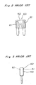
- a known fuse puller 50 includes a pair of arms 51 coupled with each other at their intermediate portions by a coupling beam 52 and two pairs of claws 54 and 55 for gripping a fuse, which project from an inner face of one end portion of each of the arms 51.
- a pair of grips 59 disposed at the other end portion of each of the arms 51 are grasped so as to separate the claws 54 and 55 away from each other with the coupling beam 52 as a fulcrum.
- the claws 54 and 55 are, respectively, brought into engagement with four slots 61 formed at opposite sides on each of opposite faces of a fuse body 62 of a fuse 60 as shown in Figs. 2 and 3.
- the grips 59 is pulled out of the fuse mounting portion.
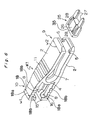
- fuse mounting portions 31 are frequently disposed at four corners of a side wall 32 of the electrical connection box 30 as shown in Fig. 4.
- the side wall 32 is formed high for waterproofing, merely small gaps s1 and s2 exist between the high side wall 32 and the fuse puller 50 at a fuse mounting portion 31' disposed at one of the corners of the fuse box.
- a molding die 65 for forming the fuse puller 50 includes a pair of split dies 66 separated from each other along a parting line S' corresponding to a lateral center of the arms 51 as shown in Fig. 5.
- the claws 54 and 55 projecting from the opposite sides of each of the arms 51 prevent the split dies 66 from separated from each other along the one-dot chain line in Fig. 5 so as to be released from each other in the directions of the arrows A. Accordingly, a central sliding die 68 for forming a region of the fuse puller 50 interposed between the arms 51 is required to be provided.
- EP-A-0 348 871 discloses a fuse puller according to the preamble of claim 1, in which each of the arms has only a single claw which extends over the whole width of the arm. This fuse puller is usable only for fuses which have a specific shape so that they may be gripped by the two claws.
- a second object of the present invention is to provide a fuse puller which enables a fuse to be pulled out of a fuse mounting portion easily and positively even when only a small space is available.
- the first claw is provided at one side of one end of the inner face of one of the arms and the second claw is provided at the other side of the inner face of the other of the arms such that the first and second claws are disposed diagonally to each other on the arms. Therefore, a molding die used for integral molding of the fuse puller can be formed by only a pair of split dies and thus, a hitherto necessary sliding die is not required to be employed for the molding die.
- the fuse puller only two claws are provided but the two claws are disposed diagonally to each other. Therefore, the fuse puller can be pulled outwardly stably upon engagement of the claws with the slots of the fuse.
- a fuse puller for pulling a fuse out of a fuse mounting portion comprises: a pair of elongated platelike arms; an elastic coupling beam for coupling longitudinally intermediate portions of the arms with each other such that the arms are longitudinally divided into a fuse engageable portion and a grip of the fuse puller by the coupling beam; and a claw member which projects from one end of an inner face of each of the arms at the fuse engageable portion so as to be brought into engagement with the fuse; wherein a first width of the arms at the grip is set smaller than a second width of the arms at the fuse engageable portion.
- the first width of the arms at the grip is made small, gap between the grip and a side wall of a fuse box can be increased. Therefore, an operator depresses the opposite outer faces of the arms at the grip so as to separate the claws away from each other such that the claws are brought into engagement with the slots of the fuse, respectively. Thereafter, in order to pull the fuse puller outwardly, the opposite side faces of the arms at the grip, which are spaced the first width of the arms from each other, are clipped by shifting fingers. Thus, fingers can be inserted into the gap between the grip and the side wall of the fuse box.
- the fuse puller can also be used for inserting the fuse into the fuse mounting portion in a state where the fuse puller is held in engagement with the fuse.
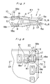
- the fuse puller K1 is formed by integral molding of resin and includes a pair of arms 2 each formed by an elongated plate and an elastic coupling beam 4 for coupling longitudinally intermediate portions of the arms 2 with each other.
- the arms 2 are longitudinally divided into a fuse engageable portion 9 and a grip 10 of the fuse puller K1 by the coupling beam 4.
- the fuse puller K1 further includes a rib 7 which extends at a lateral center of an inner face of each of the arms 2 from an inner peripheral surface of the coupling beam 4 towards the fuse engageable portion 9 so as to bridge the arms 2.
- the fuse engageable portion 9 includes two pairs of claws 5 and 6 for gripping a fuse 25, which project from one end of an inner face of each of the arms 2 at the fuse engageable portion 9.
- Each of the arms 2 is laterally expanded obliquely outwardly at a predetermined angle towards the fuse engageable portion 9 from its portion deviating from the coupling beam 4 in a direction away from the fuse engageable portion 9 such that opposite side faces of each of the arms 2 extend rectilinearly in parallel in the fuse engageable portion 9.
- each of the arms 2 has a width w2.
- a plurality of bosses 8 for preventing slip of fingers at the time of pulling the fuse 25 out of a fuse mounting portion 31 are formed on each of opposite side faces of the other end portion of each of the arms 2.
- a small width portion 18 having a predetermined width w1 which is about 50 to 65 % of the width w2 is provided at the other end portion of each of the arms 2.
- the width w1 is set to 5 mm, while the width w2 is set to 8 mm.
- a pair of stoppers 15 project towards each other from distal end portions of the arms 2 and a rib 16 extends from each of the stoppers 15 to the coupling beam 4 at a lateral center of an inner face of each of the arms 2 so as to reinforce each of the arms 2 in the grip 10.
- a plurality of laterally extending bosses 11 are provided at a substantially longitudinally central portion of an outer face of each of the arms 2.
- the fuse mounting portion 31 has large space for using the fuse puller K1
- the fuse 25 can be pulled out of the fuse mounting portion 31 by grasping the bosses 11.
- the coupling beam 4 is arcuately projected from the fuse engageable portion 9 towards the grip 10 such that the coupling beam 4 and the fuse engageable portion 9 are formed into a substantially U-shaped configuration. Since the coupling beam 4 is formed into the U-shaped configuration as described above and the arms 2 are inclined towards each other at the fuse engageable portion 9, the arms 2 are urged by the elastic coupling beam 4 in a direction for moving the claws 5 and 6 towards each other. A portion of the coupling beam 4, which is coupled with each of the arms 2, is rounded such that stress concentration does not happen at the portion of the coupling beam 4.
- the U-shaped rib 7 extends from the inner peripheral surface of the coupling beam 4 at a lateral center of the inner face of each of the arms 2 in the fuse engageable portion 9.
- a pair of protrusions 17 are, respectively, provided at opposite ends of the rib 7 so as to project towards each other.
- the protrusions 17 are brought into contact with an upper end face of a fuse body 26 of the fuse 25 such that a portion 35 of the fuse 25, which is disposed between the upper end face of the fuse body 26 and the slots 28, is gripped by the protrusions 17 and the claws 5 and 6 as shown in Fig. 9. Therefore, in addition to engagement of the claws 5 and 6 with the fuse 25, the protrusions 17 serve to fix the fuse puller K1 to the fuse 25 more securely.
- the two pairs of the claws 5 and 6 are provided at opposite sides of the inner face of each of the arms 2 at the distal end of each of the arms 2 in the fuse engageable portion 9.
- a front end of each of the claws 5 and 6 is formed so as to extend obliquely downwardly in a direction away from the coupling beam 4, while rear ends of the claws 5 and 6 extend orthogonally from the inner face of each of the arms 2 so as to act as engageable faces 5a and 6a, respectively.
- the fuse 25 employed in this embodiment is of known shape in general use and includes the fuse body 26 formed by insulating resin and a pair of terminal plates 27. One end portion of each of the terminal nal plates 27 is embedded in the fuse body 26, while the other end portion of each of the terminal plates 27 projects out of the fuse body 26. A pair of slots 28 are formed at opposite sides of the fuse body 26 so as to receive the claws 5 and 6 of the fuse puller K1.
- a fuse box 30 shown in Figs. 8 to 10 is installed in an engine room of a motor vehicle and a plurality of the fuse mounting portions 31 are provided at corners of a side wall 32 of the fuse box 30.
- the side wall 32 is formed high for waterproofing.
- the small width portions 18 disposed at one end of each of the arms 2 in the grip 10 are initially depressed towards each other by grasping opposite outer faces 18a of the small width portions 18 of the arms 2 with fingers.
- the other ends of the arms 2 at the fuse engageable portion 9 are separated away from each other with the coupling beam 4 as a fulcrum.
- the claws 5 and 6 can be brought into engagement with the slots 28 of the fuse 25. Then, by releasing the grip 10 from depression, the claws 5 and 6 are held in engagement with the slots 28 of the fuse 25, respectively.
- the bosses 8 are provided on the opposite side faces 18b of each of the arms 2, while the claws 5 and 6 are provided on the inner face of each of the arms 2. Therefore, even if the bosses 8 are clipped strongly when the fuse puller K1 is pulled outwardly, the claws 5 and 6 are not separated away from each other. Accordingly, in the course of pulling the fuse puller K1 outwardly, such a phenomenon does not occur that the claws 5 and 6 are separated away from each other and thus, the fuse 25 falls off the fuse puller K1. As a result, the fuse 25 can be pulled out of the fuse mounting portion 31 by positively holding the fuse 25 with the fuse puller K1.
- the fuse 25 held by the fuse puller K1 when the fuse 25 held by the fuse puller K1 is inserted into the fuse mounting portion 31, the fuse 25 may be inserted into the fuse mounting portion 31 by clipping the bosses 8 in a state where the claws 5 and 6 are held in engagement with the slots 28. In this case, in the course of insertion of the fuse 25 into the fuse mounting portion 31, the fuse 25 does not fall off the fuse puller K1 through disengagement of the claws 5 and 6 from the slots 28 of the fuse 25. In addition, after the fuse 25 has been inserted into the fuse mounting portion 31, fingers for clipping the bosses 8 of the grip 10 of the fuse puller K1 are shifted so as to grasp the opposite outer faces 18a of the small width portions 18 of the grip 10 of the fuse puller K1.
- the opposite outer faces 18a of the small width portions 18 of the grip 10 are depressed towards each other so as to separate the claws 5 and 6 away from each other such that the claws 5 and 6 are brought out of engagement with the slots 28.
- the fuse puller K1 can be detached from the fuse 25 so as to be taken out of the fuse box 30.
- Fig. 11 shows a fuse puller K2 according to a second embodiment of the present invention.
- the fuse puller K2 has a substantially U-shaped configuration and includes a pair of platelike arms 2'. One end of one of the arms 2' and one end of the other of the arms 2' are coupled with each other by an arcuate elastic coupling beam 4'.
- two pairs of claws 5' and 6' (not shown) for gripping a fuse 25' are projected from the other end of an inner face of each of the arms 2'.
- This fuse puller K2 is used exclusively for pulling the fuse 25' out of the fuse mounting portion 31.
- the fuse 25' includes a pair of terminal plates 27' and a projection 29 provided at an upper end of a fuse body 26'.
- the arms 2' are deflected with the coupling beam 4' as a fulcrum so as to be separated away from each other.
- the arms 2' are displaced towards each other by elasticity of the coupling beam 4' such that the claws 5' and 6' are brought into engagement with a lower face of the projection 29.
- a rectangular grip 10' having a small width w4 between a pair of opposite side faces 10'a projects from a central portion of an outer peripheral surface of the coupling beam 4'.
- Bosses 8' are formed on four side faces, i.e., the opposite side faces 10'a and another pair of opposite side faces 10'b of the grip 10'. Meanwhile, the bosses 8' may also be formed on a pair of the opposite side faces 10'a or the opposite side faces 10'b of the grip 10', preferably, a pair of the opposite side faces 10'a.
- width of the grip of the fuse puller is made small. Therefore, even in case gap between the fuse mounting portion and the side wall of the fuse box is small, space for inserting fingers thereinto can be secured between the grip of the fuse puller and the side wall of the fuse box and thus, the fuse can be easily pulled out of the fuse mounting portion by the fuse puller. Furthermore, when the fuse puller is taken out of the fuse box, the opposite side faces of the grip of the fuse puller are clipped in a direction which is not associated with separation of the claws away from each other, so that the fuse does not fall off the fuse puller through disengagement of the claws from the slots of the fuse. Therefore, the fuse can be pulled out of the fuse mounting portion by positively holding the fuse with the fuse puller.
- the fuse puller of the second embodiment since the narrow grip is provided, the fuse can be easily pulled out of the fuse mounting portion even when space between the fuse mounting portion and the side wall of the fuse box is small. Furthermore, the fuse puller can be not only inserted into the fuse box but pulled out of the fuse box by grasping identical side faces of the grip of the fuse puller without the need for shifting grasping position of fingers on the grip as in the first embodiment.
- bosses are provided on the opposite narrow side faces of each of the arms, fingers do not slip when the fuse is pulled out of the fuse mounting portion by the fuse puller. Moreover, the bosses of the arms enable an operator to immediately perceive grasping position on the fuse puller.
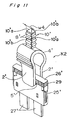
- Figs. 12 and 13 show a fuse puller K3 according to a third embodiment of the present invention.
- the single claw 5 is provided at one side of one end portion of an inner face of one of the arms 2, while the single claw 6 is provided at the other side of one end portion of an inner face of the other of the arms 2 such that the claws 5 and 6 deviate from each other in a lateral direction of the arms 2.
- the claws 5 and 6 are disposed diagonally to each other on the arms 2. Since other constructions of the fuse puller K3 are similar to those of the fuse puller K1, the description is abbreviated for the sake of brevity.
- a die 36 used for injection molding of the fuse puller K3 can be formed by split dies 37 and 38 as shown in Fig. 14. Namely, a parting line S of the split dies 37 and 38 is disposed at a lateral center of the arms 2.
- the split die 37 for the claw 6 traverses the parting line S along a distal end of the claw 6 and penetrates to an inner side of the claw 5, while the split die 38 for the claw 5 traverses the parting line S along a distal end of the claw 5 and penetrates to an inner side of the claw 6.
- the split dies 37 and 38 can be released from each other in the directions of the arrows B in Fig. 14 and thus, a hitherto necessary sliding die is not required to be provided. Since the die 36 for molding the fuse puller K3 is formed by only the split dies 37 and 38 as described above, molding time for the fuse puller K3 can be shortened, thereby resulting in rise of productivity and drop of production cost of the die 36.
- the opposite outer faces 18a of the small width portions 18 of the grip 10 are grasped so as to be depressed towards each other such that distal ends of the arms 2 at the fuse engageable portion 9 are separated away from each other.
- the claws 5 and 6 ride over the fuse body 26 of the fuse 25 so as to be brought into engagement with the slots 28.
- the claw 5 is brought into engagement with one of the two slots 28 formed on one face of the fuse 25, while the claw 6 is brought into engagement with one of the two slots 28 formed on the other face of the fuse 25 such that the slots 28 receiving the claws 5 and 6, respectively are disposed diagonally to each other in the fuse 25.
- the fuse puller K3 has the only two claws 5 and 6. Therefore, in comparison with the four claws of the fuse puller K1, force of engagement of the claws with the slots in the fuse puller K3 is reduced to half of that of the fuse puller K1 on the assumption that the claws in the fuse pullers K1 and K2 have an identical shape.
- the U-shaped rib 7 extends from the coupling beam 4 towards the claws 5 and 6 and urging force oriented in a direction for moving the claws 5 and 6 towards each other is applied from the coupling beam 4 to the rib 7, the claws 5 and 6 are urged in a direction for bringing the claws 5 and 6 into engagement. Therefore, even if the number of the claws in the fuse puller K3 is only two, force of engagement of the claws with the slots in the fuse puller K3 is large such that reduction of the number of the claws in the fuse puller K3 is compensated for.
- the fuse puller K3 can be used for inserting the fuse 25 into the fuse mounting portion 31.
- the first claw is provided at one side of the one end portion of the inner face of one of the arms and the second claw is provided at the other side of the one end portion of the inner face of the other of the arms such that the first and second claws deviate from each other in the lateral direction of the arms. Therefore, a hitherto necessary sliding die is not required to be used for the die for molding the fuse puller, which has the parting line at the lateral center of the arms. As a result, molding time can be shortened and production cost of the die can be reduced.
- the U-shaped rib is formed on the inner faces of the arms so as to extend from the coupling beam towards the claws, force of engagement of the claws with the slots of the fuse can be increased by the rib.
- the protrusions are provided at the opposite ends of the rib, respectively so as to project towards each other such that the portion of the fuse disposed between the upper end face of the fuse body and the slots is gripped by the protrusions and the claws, force for holding the fuse by the fuse puller is further increased. Accordingly, when the fuse is pulled out of the fuse mounting portion by using the fuse puller, drop of the holding force of the fuse puller due to reduction of the number of the claws can be compensated for.
Landscapes
- Fuses (AREA)
Claims (6)
- Vorrichtung (K3) zum Ausziehen einer Sicherung (25) aus einem Sicherungssockel (31), welche Ausziehvorrichtung in einem Stück aus Kunststoff geformt ist und aufweist:dadurch gekennzeichnet, daßzwei längliche plattenförmige Arme (2),einen elastischen Verbindungsbalken (4) zum Verbinden von in Längsrichtung mittleren Teilen der Arme (2) miteinander,eine erste Klaue (5), die von einem Ende einer Innenfläche eines der Arme (2) vorspringt, um mit der Sicherung (25) in Berührung gebracht zu werden,eine zweite Klaue (6), die von einem Ende einer Innenfläche des anderen der Arme (2) vorspringt, um mit der Sicherung (25) in Berührung gebracht zu werden, undeinen mit dem elastischen Verbindungsbalken (4) verbunden Griff (10),
die erste Klaue (5) auf einer Seite der Ausziehvorrichtung und die zweite Klaue (6) auf der anderen Seite der Ausziehvorrichtung angeordnet ist, so daß die ersten und zweiten Klauen (5, 6) diagonal zueinander an den Armen (2) angeordnet sind. - Ausziehvorrichtung nach Anspruch 1, bei der die Breite des Griffes (10) in der zu den Ebenen der beiden plattenförmigen Arme (2) parallelen Richtung kleiner ist als die Breite jedes dieser Arme (2) in der Nähe der Klauen (5, 6).
- Ausziehvorrichtung nach Anspruch 2, bei der der elastische Verbindungsbalken (4) in Längsrichtung mittlere Teile der Arme (2) so miteinander verbindet, daß die Arme (2) durch den Verbindungsbalken (4) in Längsrichtung unterteilt werden in einen mit der Sicherung in Eingriff bringbaren Abschnitt (9) und einen Abschnitt, der Teil des Griffes (10) ist, und eine erste Breite (w1) der Arme (2) an dem Griff (10) kleiner ist als eine zweite Breite (w2) der Arme (2) in dem mit der Sicherung in Eingriff bringbaren Abschnitt (9).
- Ausziehvorrichtung nach Anspruch 2 oder 3, bei der an dem Griff (10) mehrere Griffigkeitsvorsprünge (8) an jeder von zwei entgegengesetzten Seitenflächen (18b) des Griffes ausgebildet sind, welche Seitenflächen (18b) in einer zu den Ebenen der plattenförmigen Arme (2) parallelen Richtung zueinander beabstandet sind.
- Ausziehvorrichtung nach einem der vorstehenden Ansprüche, bei der der Verbindungsbalken (4) bogenartig geformt ist und eine U-förmige Rippe (7) so ausgebildet ist, daß sie sich in einer Breitenmitte einer Innenfläche jedes der Arme (2) von einer inneren Umfangsfläche des Verbindungsbalkens (4) in Richtung auf die mit den Klauen (5, 6) versehenen Enden der Arme (2) erstreckt.
- Ausziehvorrichtung nach Anspruch 5, bei der zwei Vorsprünge (17) an entgegengesetzten Enden der Rippe (7) ausgebildet sind, so daß sie aufeinander zu vorspringen und ein Teil (35) der Sicherung (25) von den Vorsprüngen und den Klauen (5, 6) erfaßt wird.
Applications Claiming Priority (6)
| Application Number | Priority Date | Filing Date | Title |
|---|---|---|---|
| JP26976494 | 1994-11-02 | ||
| JP269764/94 | 1994-11-02 | ||
| JP26976494A JPH08138526A (ja) | 1994-11-02 | 1994-11-02 | ヒューズプラー |
| JP26976794A JPH08138527A (ja) | 1994-11-02 | 1994-11-02 | ヒューズプラー |
| JP26976794 | 1994-11-02 | ||
| JP269767/94 | 1994-11-02 |
Publications (2)
| Publication Number | Publication Date |
|---|---|
| EP0710974A1 EP0710974A1 (de) | 1996-05-08 |
| EP0710974B1 true EP0710974B1 (de) | 1999-07-07 |
Family
ID=26548904
Family Applications (1)
| Application Number | Title | Priority Date | Filing Date |
|---|---|---|---|
| EP95116961A Expired - Lifetime EP0710974B1 (de) | 1994-11-02 | 1995-10-27 | Vorrichtung zum Ziehen von Sicherungen |
Country Status (3)
| Country | Link |
|---|---|
| US (1) | US5666865A (de) |
| EP (1) | EP0710974B1 (de) |
| DE (1) | DE69510639T2 (de) |
Families Citing this family (28)
| Publication number | Priority date | Publication date | Assignee | Title |
|---|---|---|---|---|
| USD440132S1 (en) | 1998-03-25 | 2001-04-10 | Navajo Manufacturing Company | Fuse puller |
| USD419840S (en) * | 1998-08-11 | 2000-02-01 | Navajo Manufacturing Company | Fuse puller |
| US6750056B2 (en) * | 2001-09-06 | 2004-06-15 | Roger A. Acey | Metal binding proteins and associated methods |
| ES1048273Y (es) * | 2001-02-02 | 2001-12-01 | Lear Automotive Eeds Spain | Pinza extractora perfeccionada de fusibles y reles. |
| JP4226362B2 (ja) * | 2003-03-12 | 2009-02-18 | 矢崎総業株式会社 | ヒューズ |
| EP1611653B1 (de) * | 2003-04-04 | 2008-06-25 | Yazaki Corporation | Sicherungsraumstruktur und elektrische verbinderdose |
| DE10330263B3 (de) * | 2003-07-04 | 2005-03-03 | Lisa Dräxlmaier GmbH | Vorrichtung zum Herausziehen bzw. Einsetzen einer Sicherung |
| US6871567B2 (en) * | 2003-08-01 | 2005-03-29 | Lear Corporation | Fuse and relay puller |
| US7089658B2 (en) * | 2003-11-12 | 2006-08-15 | Bellsouth Intellectual Property Corporation | Clamp remover |
| US20050260886A1 (en) * | 2004-05-20 | 2005-11-24 | Leonard Persits | Fuse block cover |
| WO2006047258A1 (en) * | 2004-10-22 | 2006-05-04 | Panduit Corp. | Push-pull plugs and tools |
| US7394343B2 (en) * | 2005-11-14 | 2008-07-01 | Wen-Tsung Cheng | Blade fuse tester having lamp |
| USD549058S1 (en) * | 2006-11-09 | 2007-08-21 | Pacific Engineering Corp. | Fuse puller |
| JP4408918B2 (ja) * | 2007-07-19 | 2010-02-03 | 本田技研工業株式会社 | ヒューズプラー |
| JP4472741B2 (ja) * | 2007-09-28 | 2010-06-02 | 矢崎総業株式会社 | ヒューズプラーおよび電気接続箱 |
| USD623490S1 (en) | 2009-09-25 | 2010-09-14 | Michael Lauber | Mortar master blade |
| US8464412B2 (en) * | 2010-01-19 | 2013-06-18 | Cheng Uei Precision Industry Co., Ltd. | Clutching jig |
| US10692679B2 (en) * | 2012-04-18 | 2020-06-23 | Eaton Intelligent Power Limited | Modular fuse removal tool accessory, kit, and systems for fusible disconnect device |
| USD729022S1 (en) | 2013-01-23 | 2015-05-12 | Pacific Engineering Corp. | Fuse puller |
| JP1524792S (de) * | 2014-01-23 | 2015-06-01 | ||
| US9702921B2 (en) | 2014-11-11 | 2017-07-11 | Dustin Scabarozi | Multi-purpose tool for blade fuses |
| JP6262178B2 (ja) * | 2015-09-03 | 2018-01-17 | 矢崎総業株式会社 | 電気接続箱 |
| USD839449S1 (en) * | 2016-10-27 | 2019-01-29 | Keter Plastic Ltd. | Sawhorse |
| US10271617B2 (en) * | 2016-10-31 | 2019-04-30 | Namra LLC | Device and system for assisting actuation of a buckle release |
| CN106981405A (zh) * | 2017-05-09 | 2017-07-25 | 上海沪工汽车电器有限公司 | 一种汽车电气盒保险丝专用插装工具 |
| US11332056B2 (en) * | 2019-08-22 | 2022-05-17 | Ykk Corporation | Seat cover fastening clip |
| CN113363122B (zh) * | 2021-06-09 | 2025-04-22 | 广汽本田汽车有限公司 | 一种保险丝多排拔出工具 |
| USD1055283S1 (en) * | 2022-03-15 | 2024-12-24 | Checkpoint Surgical, Inc. | Nerve cutting device |
Family Cites Families (12)
| Publication number | Priority date | Publication date | Assignee | Title |
|---|---|---|---|---|
| US1363515A (en) * | 1918-08-20 | 1920-12-28 | Jr Godfrey Knoss | Fuse-handling tool |
| US3253327A (en) * | 1964-08-24 | 1966-05-31 | Burroughs Corp | Manually operable inserting tool |
| GB1427397A (en) * | 1973-04-24 | 1976-03-10 | Ici Ltd | Forceps |
| US4079765A (en) * | 1975-02-19 | 1978-03-21 | Vincent Hatayan | Implement for holding and guiding nails |
| US4094212A (en) * | 1977-04-07 | 1978-06-13 | Fischer & Porter Company | Fuse-mate |
| US4212305A (en) * | 1978-03-02 | 1980-07-15 | Dart Industries Inc. | Disposable forceps |
| US4330936A (en) * | 1981-02-23 | 1982-05-25 | Swarth Oscar S | Compressed tablet-splitting holder |
| US4475283A (en) * | 1982-04-01 | 1984-10-09 | Littelfuse, Inc. | Combination fuse puller and fuse condition indicator |
| US4541311A (en) * | 1982-05-03 | 1985-09-17 | Idea Pioneer, Inc. | Fuse puller |
| JPH044345Y2 (de) * | 1988-06-28 | 1992-02-07 | ||
| US5267493A (en) * | 1988-06-28 | 1993-12-07 | Yazaki Corporation | Fuse puller |
| US5044058A (en) * | 1989-08-24 | 1991-09-03 | Voss Barbara A | Bulb insertion and removal tool |
-
1995
- 1995-10-24 US US08/547,192 patent/US5666865A/en not_active Expired - Fee Related
- 1995-10-27 DE DE69510639T patent/DE69510639T2/de not_active Expired - Fee Related
- 1995-10-27 EP EP95116961A patent/EP0710974B1/de not_active Expired - Lifetime
Also Published As
| Publication number | Publication date |
|---|---|
| DE69510639D1 (de) | 1999-08-12 |
| US5666865A (en) | 1997-09-16 |
| EP0710974A1 (de) | 1996-05-08 |
| DE69510639T2 (de) | 2000-01-27 |
Similar Documents
| Publication | Publication Date | Title |
|---|---|---|
| EP0710974B1 (de) | Vorrichtung zum Ziehen von Sicherungen | |
| US6665914B2 (en) | Clip | |
| EP1887902B1 (de) | Kunststoffbefestigungsvorrichtung | |
| CN101688549B (zh) | 扣件 | |
| JP3949401B2 (ja) | ワイヤハーネス用クランプ | |
| EP0761984A1 (de) | Schnappverbindung für zwei Bauteile | |
| KR100350606B1 (ko) | 측부압압 개방형 버클 | |
| US5702021A (en) | Locking construction of electric connection box | |
| US4975075A (en) | Locking mechanism for a connector | |
| JPH0718088U (ja) | ワイヤハーネス用スタッドボルト型クランプ | |
| JPH07245139A (ja) | 二重係止コネクタ及びその係止解除構造 | |
| US6817089B2 (en) | Connector release tool | |
| US6994597B2 (en) | Connector enabling secure retention of contacts relative to insulator | |
| JP2595172Y2 (ja) | ワイヤハーネス用クランプ | |
| US5545056A (en) | Electrical connector mounting construction of electrical connector holder | |
| US11912482B2 (en) | Clips | |
| JPH08230515A (ja) | クラスタの取付け構造 | |
| US20250377002A1 (en) | Vehicle interior part attaching structure | |
| JPH08138526A (ja) | ヒューズプラー | |
| JP2025110462A (ja) | 電気部品引抜具固定構造及び電気接続箱 | |
| JP3362683B2 (ja) | 線材束の保持具 | |
| JPH09135087A (ja) | 電気接続箱のリレーロック構造 | |
| JPH05335052A (ja) | 配線接続装置 | |
| JPH08275347A (ja) | ワイヤハーネス用クランプ | |
| JP2595109Y2 (ja) | 電気機器の取付装置 |
Legal Events
| Date | Code | Title | Description |
|---|---|---|---|
| PUAI | Public reference made under article 153(3) epc to a published international application that has entered the european phase |
Free format text: ORIGINAL CODE: 0009012 |
|
| 17P | Request for examination filed |
Effective date: 19951027 |
|
| AK | Designated contracting states |
Kind code of ref document: A1 Designated state(s): DE GB |
|
| 17Q | First examination report despatched |
Effective date: 19980515 |
|
| GRAG | Despatch of communication of intention to grant |
Free format text: ORIGINAL CODE: EPIDOS AGRA |
|
| GRAG | Despatch of communication of intention to grant |
Free format text: ORIGINAL CODE: EPIDOS AGRA |
|
| GRAH | Despatch of communication of intention to grant a patent |
Free format text: ORIGINAL CODE: EPIDOS IGRA |
|
| GRAH | Despatch of communication of intention to grant a patent |
Free format text: ORIGINAL CODE: EPIDOS IGRA |
|
| GRAA | (expected) grant |
Free format text: ORIGINAL CODE: 0009210 |
|
| AK | Designated contracting states |
Kind code of ref document: B1 Designated state(s): DE GB |
|
| REF | Corresponds to: |
Ref document number: 69510639 Country of ref document: DE Date of ref document: 19990812 |
|
| PLBE | No opposition filed within time limit |
Free format text: ORIGINAL CODE: 0009261 |
|
| STAA | Information on the status of an ep patent application or granted ep patent |
Free format text: STATUS: NO OPPOSITION FILED WITHIN TIME LIMIT |
|
| 26N | No opposition filed | ||
| PGFP | Annual fee paid to national office [announced via postgrant information from national office to epo] |
Ref country code: GB Payment date: 20011031 Year of fee payment: 7 |
|
| PGFP | Annual fee paid to national office [announced via postgrant information from national office to epo] |
Ref country code: DE Payment date: 20011112 Year of fee payment: 7 |
|
| REG | Reference to a national code |
Ref country code: GB Ref legal event code: IF02 |
|
| PG25 | Lapsed in a contracting state [announced via postgrant information from national office to epo] |
Ref country code: GB Free format text: LAPSE BECAUSE OF NON-PAYMENT OF DUE FEES Effective date: 20021027 |
|
| PG25 | Lapsed in a contracting state [announced via postgrant information from national office to epo] |
Ref country code: DE Free format text: LAPSE BECAUSE OF NON-PAYMENT OF DUE FEES Effective date: 20030501 |
|
| GBPC | Gb: european patent ceased through non-payment of renewal fee |