EP0707959A1 - Procédé de sérigraphie et dispositif pour la mise en oeuvre dudit procédé - Google Patents
Procédé de sérigraphie et dispositif pour la mise en oeuvre dudit procédé Download PDFInfo
- Publication number
- EP0707959A1 EP0707959A1 EP95115595A EP95115595A EP0707959A1 EP 0707959 A1 EP0707959 A1 EP 0707959A1 EP 95115595 A EP95115595 A EP 95115595A EP 95115595 A EP95115595 A EP 95115595A EP 0707959 A1 EP0707959 A1 EP 0707959A1
- Authority
- EP
- European Patent Office
- Prior art keywords
- printing
- holder
- transport
- screen printing
- toothed belt
- Prior art date
- Legal status (The legal status is an assumption and is not a legal conclusion. Google has not performed a legal analysis and makes no representation as to the accuracy of the status listed.)
- Granted
Links
Images


Classifications
-
- B—PERFORMING OPERATIONS; TRANSPORTING
- B41—PRINTING; LINING MACHINES; TYPEWRITERS; STAMPS
- B41F—PRINTING MACHINES OR PRESSES
- B41F15/00—Screen printers
- B41F15/08—Machines
- B41F15/0872—Machines for printing on articles having essentially cylindrical surfaces
- B41F15/0877—Machines for printing on articles having essentially cylindrical surfaces of varying cross-section
Definitions
- the invention relates to a method and a device for printing individual objects using the screen printing method.
- a screen printing machine in which a number of separate, coordinated controllable drive motors for the movement of the individual organs, in particular the holder for the object to be printed and the screen holder, are provided.
- the only bracket is attached to the front of the machine so that it can be moved back and forth.
- This machine has only a low productivity, since only one holder is provided, which can also be moved beyond the pressure range up to a feed conveyor on one side and a discharge conveyor on the other side.
- the object after the end of the last printing process and possibly drying, the object must first be removed from the holder before the holder can then be moved back to its starting position in order to pick up the next object there.
- the low productivity of this device is particularly evident in devices with several printing stations for applying, for example, a printed image which consists of several colors.
- the invention has for its object inter alia to design program-controlled screen printing machines of the type described above so that a greater throughput can be achieved without the number of printing stations having to be increased. It is also sought that the relative movements of the parts interacting during the printing process, in particular between screen printing stencil, squeegee and object to be printed, can be precisely coordinated in order to achieve good print quality.
- the invention proposes that at least two brackets and a special transport means are provided for each holder and each transport means for a holder is driven by a special NC motor.
- the means of transport preferably transports the associated holder along a closed orbit between a station in which the object to be printed is inserted into the holder and a station in which the printed object is removed from the holder, the means of transport in individual cases if necessary Printing stations also transmits to the holder the linear movements that are required during the printing process in order to hold the object and doctor blade to be printed in the relative position required for the printing process.
- each holder has its own, separately driven means of transport, which advantageously takes the form of a rotating toothed belt has, it is possible to control all holders independently of one another with regard to their transport, so that one holder with the object carried by it passes through, for example, several printing stations arranged one behind the other in the direction of transport, whereas another holder can be brought independently into the station in Which of the printed articles is removed from the holder and can then, if necessary, be immediately moved back into the receiving station in order to pick up the next object there without being dependent on the transport steps or the transport speed of the at least one other holder.
- a special transmission means can be provided for each holder, via which the rotational movements which the holder and the object carried by it during the printing process are transmitted to the holder.
- a toothed belt is expediently used, which engages with a toothed belt wheel which is connected to the holder.
- the individual transmission means are also driven by separate NC motors, with the result that the swiveling or rotating movements of the holders can be carried out with great accuracy during printing in order to achieve the desired high print quality. This is particularly important when printing objects with an irregular cross-sectional shape.
- the holder For objects such as bottles, which are normally due to their shape when printing or when performing other treatments in the device at both ends, usually bottom and neck, are held, the holder consists of two parts that are moved synchronously.
- the arrangement is such that each holder part is transported by a special toothed belt and furthermore a special toothed belt is provided for each holder part in order to transmit the rotational movements required during the printing process to the object.
- the two toothed belts for transport and the two toothed belts for transmitting the rotational movements are each assigned a common NC motor. It is of course also possible to use one-piece brackets if the shape of the object requires it or makes it possible.
- the configuration according to the invention ensures that the masses to be moved are relatively small. This also benefits the accuracy of the printing process and thus the quality of the printed image.
- the screen printing stencil and squeegee of the at least one printing unit can be moved up and down synchronously in order to compensate for the vertical displacements of the area of the object to be printed that occur during printing in the case of irregularly shaped objects. In this case it is not required that the object undergoes a vertical shift when printed.
- the screen printing machine 10 is also provided in the area of the outer printing stations I and IV with vertical guides 21 which are attached directly to the machine frame 19. A slide 20 is guided on each of these guides 21. An elongated support 29 is attached to both carriages 20, to which all doctor blades 14a, 14b, 14c and 14d are attached via cantilever arms 31.
- an essentially horizontal rail 34 is fastened to the carrier 29, on which two pairs of rollers 36 abut on the upper and lower sides, which, as shown in particular in FIG. 2, are each attached to the two slides 25 which run along the guides 23 can be moved up and down.
- the back and forth movements of the base slide 16 in the direction of the arrows 17, 18 are brought about by an NC motor 38 which drives a toothed belt wheel 40 which engages with a toothed belt 42 which is also guided via a second toothed belt wheel 49.
- the toothed belt 42 is connected to the base slide 16 so that the latter and with it the guides 23 and the screen printing stencils 14a-14d connected to the base slide 16 via the slide 25 and the carrier 27 by appropriate actuation of the NC motor 38 in the direction of the arrows 17, 18 can be moved back and forth.
- the vertical movements of the printing units are brought about by an NC motor 22, which drives a shaft 24 on which two toothed belt wheels 26 are fastened, each of which engages with a toothed belt 28.
- a further shaft 30 is mounted on the machine frame, on which two toothed belt wheels 32 are fastened, each of which serves to guide one of the toothed belts 28.
- Each of the two toothed belts 28 is connected to one of the two carriages 25, so that by actuating the NC motor 22 the carrier 27 for the screen printing stencils 12a-12d and thus synchronously via the connection between the rail 34 and pairs of rollers 36 also the carrier 29 with the doctor blades 14a-14d attached thereto are moved, the carrier 29 being guided over the slides 20 on the laterally arranged guides 21.
- the doctor blades do not take part in the back and forth movements in the direction of arrows 17 and 18, wherein due to the connection via the rail 34 and the pairs of rollers 36, a relative movement between the arrangement and the doctor blade the arrangement carrying the screen printing stencils is made possible.
- the screen printing machine is provided with four printing stations, four printing images are normally applied in succession to the respective object, which can add up to an overall printing image.
- four printing images are normally applied in succession to the respective object, which can add up to an overall printing image.
- the particular type of application of the individual printed images and the possible combinations are familiar to any person skilled in the art, so that they need no special explanation here.
- a device can be attached behind each printing station, by means of which the printing ink just applied can be dried.
- Each object is carried by a bracket as it is transported through the printing press 10. There are a total of two brackets that are transported and rotated independently of one another.
- each holder consists of two holder parts 43a, 43b or 44a, 44b, of which the holder part 43a or 44a in the usual way receives the bottom portion of the object 39, whereas the spike-like holding part 43b or 44b engages in the neck of the bottle-shaped object.
- the transport path for the brackets 43a, 43b and 44a, 44b and the objects carried by them is defined by a circumferential pair of rails 46a, 46b on which the brackets are guided.
- the bracket parts 43a, 43b; 44a, 44b are carried by transport carriages 48a, 48b and 50a, 50b which interact in pairs in accordance with the function of the holding parts.
- the mounting parts 43a, 43b are attached to the carriages 48a and 48b, for example.
- the bracket parts 44a, 44b are carried by the carriages 50a and 50b, respectively.
- Each of the carriages is provided with two rollers 52a, 52b arranged in pairs, each at a height of the respective rails 46a and 46b are arranged at a corresponding distance from one another and on the respective rail 46a. 46b adjacent to serve to guide the respective carriage on the rail.
- the two rails 46a and 46b are arranged circumferentially in the vertical plane, so that an upper, substantially horizontal transport path section 53a and a vertically below, substantially parallel lower transport path section 53b are present, and both transport path sections 53a, 53b pass through at their mutually facing ends an approximately semicircular transport path section 53c and 53d are connected to each other.
- a set of shafts 54, 55 which is coaxial with it and runs essentially horizontally, is arranged in each of these two semicircular guideway sections 53c, 53d. 1, the left shaft set 54 is assigned to the pair of carriages 48a, 48b, whereas the right shaft set 55 is assigned to the pair of carriages 50a, 50b.
- the shaft set 54 is provided with a shaft 57 on which a coaxial shaft 56 is rotatably mounted, with which the toothed belt wheel 58 is fixedly connected.
- the toothed belt wheel 58 is driven by an NC motor 61 via a toothed belt 60.
- two toothed belt wheels 62a, 62b are fixedly mounted on the shaft 56, each of which drives a toothed belt 64a, 64b.
- Each of these toothed belts 64a, 64b is guided via a toothed belt wheel 66a, 66b, which is loosely arranged on the right shaft 55, in such a way that it runs parallel to the rails 46a, 46b.
- the endless toothed belt 64a running over the toothed belt wheels 62a, 66a is connected to the carriage 48a, which carries the holding part 43a.
- the endless toothed belt 64b running over the toothed belt wheels 62b and 66b is connected to the carriage 48b for the holding part 43b.
- the transport of the object carried by the holding parts 43a, 43b can thus be effected and controlled along the guideway defined by the rails 46a, 46b.
- a toothed belt wheel 70 is fixedly connected to the shaft 57 in order to transmit the movements required for this purpose, which can be driven by a NC motor 74 via a toothed belt 72 is. Furthermore, two toothed belt wheels 68a, 68b are firmly connected to the shaft 57. Each of these two toothed belt wheels drives a toothed belt 71a, 71b, which is also guided over a toothed belt wheel 75a or 75b loosely arranged on the right shaft 55.
- the endless toothed belt 71a is assigned to the carriage 48a and passed through it.
- the carriage 48a is provided with two guide rollers 83a, 83b, over which the smooth side of the toothed belt 71a runs.
- a toothed belt wheel 85 attached to the carriage, which is driven by the toothed belt 71a, is fixedly connected to a shaft 84 which carries the holding part 43a.
- actuation of the NC motor 74 results in a corresponding rotary movement of the holding part 43a and thus of the object carried by it.
- Such a rotational movement can also be brought about by merely moving the carriage 48a along its transport path determined by the rail 46a with the toothed belt 71a at a standstill. In the case of a carriage moving along the guideway, the rotational movement of the object carried by the holding part 43a would thus result from this transport movement and, if appropriate, a simultaneous movement of the toothed belt wheel 71a.
- the two carriages 50a, 50b of the holder 44a, 44b shown in the drawing in the lower position are driven in a corresponding manner via the shaft set 55 located on the right in FIG. 1 of the drawing, to which two NC motors are also assigned, of which the NC Motor 86 serves to transport the two carriages 50a, 50b along the guideway defined by the two rails 46a, 46b and the NC motor 87 drives the holding parts 44a, 44b for the purpose of rotating the object carried by them.
- a coaxial shaft 78 is rotatably mounted on the shaft 77 of the shaft set 55, with which a plurality of toothed belt wheels are firmly connected.
- the toothed belt wheel 90 is driven by the NC motor 86 via a toothed belt 67.
- toothed belt wheels 88a, 88b are fixedly mounted on the shaft 78, each of which drives a toothed belt 89a, 89b.
- Each of these toothed belts 89a, 89b is guided via a toothed belt wheel 91a, 91b, which is loosely mounted on the left shaft 57, in such a way that it runs parallel to the rails 46a, 46b.
- Both toothed belts 89a, 89b are each connected to one of the carriages 50a, 50b in order to transport it along the guideway defined by the rails 46a, 46b.
- a toothed belt wheel 92 is fixedly connected to the shaft 77 and can be driven by the NC motor 87 via a toothed belt 73. Furthermore, two toothed belt wheels 94a, 94b are firmly connected to the shaft 77. Each of these two toothed belt wheels drives a toothed belt 95a, 95b, which is also guided over a toothed belt wheel 96a, 96b arranged loosely on the left shaft 57.
- the toothed belt 95a is assigned to the carriage 50a and in passed through the carriage 50a in the manner already described in connection with the toothed belt 71a and the carriage 48a.
- the toothed belt 95b is correspondingly assigned to the carriage 50b. Both toothed belts serve to effect the rotational movement of the object carried by the holder 44a, 44b, which is necessary during printing or other treatments.
- Both shaft sets 54, 55 also carry stationary supports 35 with the interposition of suitable bearings. At the axial ends of both supports, which do not participate in the rotation of the shafts 58, 78 of the two shaft sets 54, 55, holding means 63a, 63b are attached, which the rotating ones Wear guide rails 46a, 46b.
- FIGS. 7a-7i show the process of printing an object which is elliptical in cross-section over the entire circumference of 360 °, the screen printing stencil 12a being able to be pushed back and forth in the X direction and the doctor blade 14a being arranged stationary in the X direction.
- the contour of the object 39 is shown, which is carried by the holding parts 43a, 43b, not shown, which were transported via the toothed belts 64a, 64b by the program-controlled NC motor 61 into the position according to FIG. 7a, which the Positions of the interacting parts at the beginning of the printing process shows.
- the screen printing stencil 12a which can be moved back and forth both in the direction of the X axis and in the direction of the Y axis, assumes its starting position for the printing process, which coincides with its left end position.
- the object 39 assumes a position in which its longer cross-sectional axis runs horizontally and the squeegee 14a is located vertically above the shorter cross-sectional axis of the object in the extension thereof and thus vertically above the longitudinal axis 81 of the cross-section, which in this position of the parts is also the same Longitudinal axis of the transfer area is. This means that in this position of the parts, the longitudinal axis 81 of the cross section and the longitudinal axis of the transfer area coincide.
- the distance between the longitudinal axis 81 from the screen printing stencil 12a is denoted by "b" in FIG. 7a.
- the object 39 is pivoted about its longitudinal axis 81 via the toothed belts 71a, 71b by the program-controlled NC motor 74 in the direction of the arrow 47, the screen printing stencil 12a being pivoted to the right in the direction of the X- by the program-controlled NC motor 38.
- FIG. 7b shows an intermediate stage in the course of the printing process, in which the two axes of the cross section run obliquely.
- the central axis 81 has been displaced by the distance l in the direction of the X axis with respect to the doctor blade 14a, which is stationary in the direction of the X axis.
- the necessary displacement of the holder 43a, 43b in the direction of the X-axis is also effected by the corresponding program-controlled NC motor 61, which drives the toothed belt 64a, 64b5.
- the distance between the central axis 81 and the screen printing stencil in the intermediate position according to FIG. 7b is designated by "h".
- the printing unit consisting of screen printing stencil 12a and squeegee 14a has been raised further to the distance a in order to take into account the fact that the transfer area of the position according to FIG. 7c is higher than in the position according to FIG. 7b.
- the object 39 is again laterally displaced in order to maintain the above-described position of the doctor blade 14a relative to the surface area of the object to be printed in each case, but this time the shift takes place in the opposite direction, i.e. to the left.
- the path l shown in FIG. 7d corresponds to the path l of FIG. 7b, since in both cases the object assumes essentially the same angular position to the screen printing stencil, but in each case pointing in the opposite direction.
- the printing unit has been somewhat lowered in FIG. 7d compared to the position in FIG. 7c.
- the areas to be printed on the objects shown in both exemplary embodiments do not have a circular cross section, they are regularly designed insofar as the area to be printed in each case has an elliptical cross section with two axes of symmetry.
- the invention is in no way limited to the printing of objects with such a regular cross-sectional shape. It is also possible to print objects whose area to be printed has an irregular cross section, for example including a flat surface. Furthermore, it is also possible to print objects which, for example, have an essentially square cross section, the edges being rounded and the regions located between two adjacent edges being slightly curved outwards. However, it would also be possible to print objects of this type with rounded edges if the surface located between two adjacent edges is completely flat, that is to say not curved.
- the station VI in which the bottle to be printed is placed in the holder 43a, 43b or 44a, 44b, and the station VII, in which the printed bottle is removed from the respective holder assigned to the lower section 53b of the transport path.
- the bottle to be printed is introduced into the holder located in the receiving station VI by means of a gripper 79a which can be moved three-dimensionally and which picks up the bottle transported by a conveyor 97a, and by overlapping pivoting movements, the bottle from the vertical to the horizontal position and at the same time brings into the receiving station VI, in which it is received by the two parts of the holder located there.
- the holding part 43a, 43b cooperating with the neck-side end of the bottle-shaped object 39 is arranged displaceably parallel to the longitudinal axis of the object carried by the holding parts in the respectively associated carriage 48b, 50b.
- the holding part 43b, 44b is provided with a cam roller 101 which interacts in the receiving station VI and in the removal station VII with a cam section 103 which runs parallel to the direction of transport of the object in the area of the aforementioned stations.
- the curve section 103 can be displaced transversely to the transport direction by means of a pneumatic cylinder-piston arrangement 105.
- a pneumatic cylinder-piston arrangement 105 In the course of the movement of the holder parts in the direction of arrow 17 (FIG. 1) into the removal station VII, the cam roller 101 located on the holder part 43b or 44b runs into the curve of the curve section 103.
- the gripper 79b After reaching the removal station IV, the gripper 79b is moved along the rail 99b to the end position on the left in relation to the illustration in FIG. 1 and pivoted into the removal station in order to grasp the object still located there and carried by the holding parts.
- the holding part 44b is moved away from the holding part 44a by a distance which is sufficient to release the object now carried by the gripper 79b at its neck-side end.
- the gripper then executes a short movement towards the neck-side holding part 44b in order to disengage the object from the bottom receptacle 44a.
- the gripper can move the object along the The rail 99b is displaced in the direction of the conveyor 79b and pivoted such that it places the printed object on the conveyor 79b in a vertical position, as shown in FIG. 1.
- the holder 44a, 44b can then be moved forward into the receiving station VI, the holding part 44b maintaining its position in which it is at a greater distance from the holding part 44a, so that after reaching the receiving station VI the gripper 79a is an object which it had previously moved from Has removed conveyor 97a, first brings it in a horizontal position between the two mounting parts 44a, 44b and then pushes its bottom area into the mounting 44a by a corresponding movement parallel to the longitudinal axis of the object.
- the cam section 103 located there is displaced in the direction of the mounting part 44a, taking along the cam roller 101 located in the corner of this cam section, with the result that the mounting part 44b is in the neck of the object 39 engages so that the latter is now carried by the two mounting parts.
- the gripper 79a can now release the holding part and be moved back into the position for picking up the next object.
- the cam roller 101 disengages from the curve section 103 after reaching the upper section 53a of the transport path in the direction of the arrow 18 the object is subjected to any additional treatments before it reaches the first printing station I.
- the objects can be dusted, flamed and aligned in the circumferential direction.
- the object is then brought into the first printing station I, in which the parts assume the positions described in connection with FIG. 7a immediately before the start of printing.
- the printing takes place Transport to printing station II, where the next print image is applied.
- the object After the last printed image has been applied in station IV, after passing section 53c of the transport path, the object again passes into lower section 53b and there into removal station VII, in which the object is removed from the holder in the manner already described by gripper 79b becomes.
- brackets 43a, 43b and 44a, 44b are moved independently of one another along the transport path, it is possible, for example after the last printed image has been applied, to transport the object immediately to the removal station VII and after removing the printed object from the holder to move this immediately into the recording station VI in order to pick up the next object there. It is also possible to carry out all the desired treatments in the treatment stations which may be between the receiving station VI and the printing station I, without this being impeded or delayed by the transport of the other holder (s). This results in a significant increase in productivity compared to known machines.
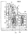
- FIGS. 8 and 9 largely coincides with the exemplary embodiment according to FIGS. 1-4, so that the same or corresponding parts are provided with the same reference numerals, but are 100 larger in FIGS. 8-11.
- the main difference between the two exemplary embodiments is that the screen printing stencils 112a, 112b, 112c, 112d, 112e of the five printing units are arranged stationary insofar as they do not make any movements parallel to their main plane, i.e. in the direction of the X axis, during the printing process .
- doctor blades 114a, 114b, 114c, 114d, 114e are essentially parallel to the main plane of the respectively associated screen printing stencil and perpendicular to the longitudinal axis of the printing object arranged to slide back and forth to effect the relative movement required for the printing process between screen printing stencil and associated doctor blade.
- each of the printing units consisting of screen printing stencil and squeegee is arranged such that it can be moved vertically up and down, in the case of objects whose surface to be printed deviates in cross-section from the course of a circle or segment of a circle, the changing altitude in the course of the pivoting movement carried out by the object to be able to follow the transfer area adjacent to the screen printing template.
- an NC motor 122 which drives a shaft 124 on which two toothed belt wheels 126 are fastened, each of which engages with a vertical toothed belt 128.
- two toothed belt wheels 132 are arranged at a distance from them, each of which serves to guide one of the toothed belts 128.
- Each of the two toothed belts 128 is connected via a cross member 109 to a slide 125 which is guided on vertical guides 121 which are fastened to the machine frame 119. All screen printing stencils 112a-112e are attached to this carriage 125.
- the carriage 125 is provided with two spaced-apart, essentially horizontal guides 115, on which a carriage 116 can be pushed back and forth essentially horizontally, which carries all the doctor blades 114a-114e via cantilever arms 131.
- the reciprocating movements of the squeegee slide 116 are effected by an NC motor 138 which drives a toothed belt wheel 140 via a shaft consisting of two telescopically interacting shaft sections 141, 145.
- a toothed belt 142 is guided around this toothed belt wheel 140 and around a second toothed belt wheel 149 arranged at a horizontal distance.
- the two toothed belt wheels 140 and 149 are arranged on a carrier 151 which is attached to the back of the carriage 125.
- the toothed belt 142 and the slide 116 guided on the guides 115 are connected to one another by at least one cross member 159, so that the back and forth movements of the slide 116 with the doctor blades located thereon are effected in the horizontal plane by the toothed belt 142.
- FIGS. 8 and 9 also corresponds in principle to that according to FIGS. 1 and 2 with regard to the means for transporting and pivoting the holders for the objects 139 and the drives required for this.
- FIG. 10 shows the arrangement of the shaft sets and the individual toothed belt wheels carried by them with the toothed belts.
- all parts which correspond to parts of the exemplary embodiment according to FIGS. 1-4 are provided with the same, but by 100 reference numerals, respectively.
- the arrangement according to FIG. 10 allows a somewhat more compact construction than the arrangement according to FIG. 4.
- FIGS. 11a-11i analogously to the illustration in FIGS. 7a-7i, the sequence of the movements of the parts interacting during the printing process is shown if the screen printing stencil is stationary parallel to the X-axis and the squeegee is displaceable parallel to the X-axis. It is necessary that the object 139 is moved in the direction of the X-axis during the printing process in order to roll the surface areas to be printed on the screen printing stencil. This movement is caused by the holder parts 143a, 143b carrying the object by the NC motor 161, which drives the two toothed belts 164a, 164b to which the two carriages 148a, 148b are connected for the holder parts transfer the object.
- the NC motor 161 which drives the two toothed belts 164a, 164b to which the two carriages 148a, 148b are connected for the holder parts transfer the object.
- the NC motor 161 is programmed in such a way that a resulting movement is effected in which the squeegee, when it reaches the position according to FIG the representation of Figure 11b, is to meet the aforementioned condition that the doctor blade is above the center or above the central axis, which belongs to the radius of curvature of the transfer area of the object surface.
- this means that the movement of the object between the two positions of FIGS. 11a and 11b lags behind the movement of the doctor blade in the same direction, namely by path 1.
- the squeegee and object are in turn moved at different speeds depending on the cross-sectional shape of the surface area to be printed in this phase, such that the object moves around the path l leads, which corresponds to the distance in the X-axis between the axis 181 by which the object is rotated and the position of the doctor blade.
- the object is in turn moved more slowly in the direction of the X axis than the doctor blade, so that the doctor blade is above the axis of rotation 181 of the object .
- FIGS. 11f-11i show the sequence of the movements when printing on the other side of the object 39.
- the sequence of the movements corresponds to the sequence described in connection with FIGS. 11a-11e.
- the two stations in which the objects to be printed are placed in the holders or the printed objects are removed from these holders are assigned to the upper section 53a of the transport path, whereas in the case of the embodiment according to Figures 1 and 2, as already explained, these stations are assigned to the lower section 53b.
- Which of the two options is preferred depends on the particular circumstances, for example on whether any pretreatments are to be carried out in the area of the transport path 53c or 153c before the first printing process takes place.
- the first printing station I is preceded by a station in the region of the upper transport path section 153a, in which the objects are aligned in the circumferential direction.
- stations II and IV of the device according to FIGS. 8 and 9 can each be replaced by a drying device, for example a UV lamp, which may be used during transport the objects can move from one printing station to the following printing station essentially synchronously with these objects if the productivity of the machine is increased as a result.
- a drying device for example a UV lamp
- the device Depending on the desired production per unit of time, it is also possible to provide the device with more than two holders.
- the application of the individual print images will take place in such a way that a printing process is only carried out in one of the total printing stations, whereas the other stations run along empty.
- printing operations can be carried out simultaneously in two stations, for example, if the vertical movements of the printing units in both stations match.
- At least one of the printing stations in another way, for example in such a way that the screen printing stencil is fixed and the squeegee is moved transversely to the transport direction 18 for applying the printing ink to the object opposite the screen printing stencil.
- Such an arrangement is useful, for example, when the object has an essentially flat surface section that is to be printed on. In this case, the screen printing stencil and the object need not be moved relative to one another during the printing process.
Applications Claiming Priority (2)
| Application Number | Priority Date | Filing Date | Title |
|---|---|---|---|
| DE4436275A DE4436275C2 (de) | 1994-10-11 | 1994-10-11 | Verfahren und Vorrichtung zum Bedrucken von Einzelobjekten |
| DE4436275 | 1994-10-11 |
Publications (2)
| Publication Number | Publication Date |
|---|---|
| EP0707959A1 true EP0707959A1 (fr) | 1996-04-24 |
| EP0707959B1 EP0707959B1 (fr) | 1998-04-29 |
Family
ID=6530467
Family Applications (1)
| Application Number | Title | Priority Date | Filing Date |
|---|---|---|---|
| EP95115595A Expired - Lifetime EP0707959B1 (fr) | 1994-10-11 | 1995-10-04 | Procédé de sérigraphie et dispositif pour la mise en oeuvre dudit procédé |
Country Status (4)
| Country | Link |
|---|---|
| US (1) | US5651308A (fr) |
| EP (1) | EP0707959B1 (fr) |
| JP (1) | JPH08207238A (fr) |
| DE (2) | DE4436275C2 (fr) |
Cited By (2)
| Publication number | Priority date | Publication date | Assignee | Title |
|---|---|---|---|---|
| WO2011144278A1 (fr) * | 2010-05-19 | 2011-11-24 | Khs Gmbh | Dispositif et procédé d'impression, en particulier d'impression polychrome de récipients |
| WO2016045220A1 (fr) * | 2014-09-24 | 2016-03-31 | 深圳市华星光电技术有限公司 | Imprimeur de sérigraphie et procédé d'impression associé |
Families Citing this family (11)
| Publication number | Priority date | Publication date | Assignee | Title |
|---|---|---|---|---|
| US5857409A (en) * | 1998-01-20 | 1999-01-12 | Dubuit Of America, Inc. | System for multi-color printing with object registration means |
| US6079326A (en) * | 1998-05-15 | 2000-06-27 | Carl Strutz & Co., Inc. | Method and apparatus for using workpiece registration to inline decorate and cure workpieces |
| DE19921306C1 (de) * | 1999-05-07 | 2000-08-03 | Schott Glas | Siebdruckvorrichtung |
| US7737349B1 (en) | 2006-08-14 | 2010-06-15 | Art Guitar, Llc | Decorating guitars |
| US7470455B2 (en) * | 2003-11-18 | 2008-12-30 | Art Guitar, Llc | Decorating guitars |
| CN100439101C (zh) * | 2004-06-01 | 2008-12-03 | 东远精技工业股份有限公司 | 悬臂式双台面网印机 |
| FR2902042B1 (fr) * | 2006-06-12 | 2015-05-15 | Dubuit Mach | Machine a imprimer |
| US8522515B2 (en) * | 2009-01-26 | 2013-09-03 | R.J. Reynolds Tobacco Company | Method and apparatus for customizing cigarette packages |
| CN102126335B (zh) * | 2011-01-27 | 2012-07-04 | 玉环县东美塑机有限公司 | 自动圆面丝印机中的丝印装置 |
| FR3001648B1 (fr) * | 2013-02-04 | 2015-07-17 | Illinois Tool Works | Machine et procede de marquage d'articles |
| WO2021167637A1 (fr) * | 2020-02-20 | 2021-08-26 | LSINC Corporation | Machine de décoration de récipient comprenant une pluralité de postes de travail d'impression indépendants |
Citations (7)
| Publication number | Priority date | Publication date | Assignee | Title |
|---|---|---|---|---|
| BE690386A (fr) * | 1965-12-22 | 1967-05-02 | ||
| EP0212486A2 (fr) | 1985-08-19 | 1987-03-04 | Hoechst Aktiengesellschaft | Matière à mouler à base de polyoléfines |
| EP0266645A1 (fr) * | 1986-11-05 | 1988-05-11 | Werner Kammann Maschinenfabrik GmbH. | Dispositif pour transporter et positionner les objets pas à pas |
| DE3730409A1 (de) | 1987-09-10 | 1989-03-23 | Balsfulland Gmbh Maschf Geb | Siebdruckmaschine |
| EP0516968A1 (fr) * | 1991-05-03 | 1992-12-09 | M.O.S.S. - S.r.l. | Machine à imprimer sérigraphique pour la décoration de la surface extérieure de récipients en général |
| EP0535512A1 (fr) * | 1991-10-01 | 1993-04-07 | Werner Kammann Maschinenfabrik GmbH. | Procédé et dispositif pour imprimer des articles au moins partiellement coniques |
| WO1995022458A1 (fr) * | 1994-02-18 | 1995-08-24 | Nassetti Usmac S.P.A. | Dispositif de serigraphie pour objets divers, et notamment pour recipients de section sensiblement elliptique ou polycentrique |
Family Cites Families (18)
| Publication number | Priority date | Publication date | Assignee | Title |
|---|---|---|---|---|
| DE266645C (fr) * | ||||
| DE535512C (de) * | 1930-02-19 | 1931-10-15 | Robert Marguerat | Bleistiftbearbeitungsmaschine |
| US3253538A (en) * | 1964-07-13 | 1966-05-31 | Strutz & Co Inc Carl | Bottle decorating apparatus |
| US3863753A (en) * | 1973-05-10 | 1975-02-04 | Anchor Hocking Corp | Chuck apparatus for supporting containers by the finish portion thereof |
| US4109573A (en) * | 1974-01-22 | 1978-08-29 | Werner Kamman Maschinenfabrik | Article, screen and squeegee drive for screenprinter |
| DE2530360C2 (de) * | 1975-07-08 | 1984-12-20 | Werner Kammann Maschinenfabrik, 4980 Bünde | Siebdruckvorrichtung |
| FR2367610A1 (fr) * | 1976-10-15 | 1978-05-12 | Dubuit Jean Louis | Dispositif de chargement pour machine a imprimer, et machine a imprimer comportant un tel dispositif |
| US4254706A (en) * | 1979-03-22 | 1981-03-10 | American Screen Printing Equipment Company | Accessory for printing oval objects |
| IT1141743B (it) * | 1980-11-14 | 1986-10-08 | Omso Spa | Dispositivo ad elevata produttivita per l'alimentazione di oggetti cilindrici alle macchine da stampa serigrafiche |
| US4502380A (en) * | 1983-04-01 | 1985-03-05 | Permanent Label Corporation | Apparatus and method for decorating articles of non-circular cross-section |
| DE3330927A1 (de) * | 1983-08-27 | 1985-03-14 | Werner Kammann Maschinenfabrik GmbH, 4980 Bünde | Vorrichtung zum dekorieren von objekten |
| US4592277A (en) * | 1985-01-09 | 1986-06-03 | Dennesen Joseph C | Drive for stencilling apparatus |
| US4712474A (en) * | 1985-11-04 | 1987-12-15 | American Screen Printing Equipment Company | Automatic article handling and screen printing apparatus |
| US4862798A (en) * | 1985-11-04 | 1989-09-05 | American Screen Printing Equipment Company | Cylindrical object screen printer with object centering means |
| US4781112A (en) * | 1987-05-04 | 1988-11-01 | American Production Machine Company | Apparatus for printing hollow containers |
| DE3936157C2 (de) * | 1989-10-31 | 1999-03-18 | Kammann Maschf Werner | Verfahren und Vorrichtung zum Bedrucken von Objekten |
| US5120392A (en) * | 1991-05-20 | 1992-06-09 | Screen-Tech Inc. | Container transport and manipulator for use with a label or screen printing applier |
| US5524535A (en) * | 1994-03-09 | 1996-06-11 | Carl Strutz & Co., Inc. | Method and apparatus for high speed decoration of bottles |
-
1994
- 1994-10-11 DE DE4436275A patent/DE4436275C2/de not_active Expired - Fee Related
-
1995
- 1995-10-04 DE DE59502043T patent/DE59502043D1/de not_active Expired - Fee Related
- 1995-10-04 EP EP95115595A patent/EP0707959B1/fr not_active Expired - Lifetime
- 1995-10-10 US US08/541,839 patent/US5651308A/en not_active Expired - Fee Related
- 1995-10-11 JP JP7288152A patent/JPH08207238A/ja active Pending
Patent Citations (7)
| Publication number | Priority date | Publication date | Assignee | Title |
|---|---|---|---|---|
| BE690386A (fr) * | 1965-12-22 | 1967-05-02 | ||
| EP0212486A2 (fr) | 1985-08-19 | 1987-03-04 | Hoechst Aktiengesellschaft | Matière à mouler à base de polyoléfines |
| EP0266645A1 (fr) * | 1986-11-05 | 1988-05-11 | Werner Kammann Maschinenfabrik GmbH. | Dispositif pour transporter et positionner les objets pas à pas |
| DE3730409A1 (de) | 1987-09-10 | 1989-03-23 | Balsfulland Gmbh Maschf Geb | Siebdruckmaschine |
| EP0516968A1 (fr) * | 1991-05-03 | 1992-12-09 | M.O.S.S. - S.r.l. | Machine à imprimer sérigraphique pour la décoration de la surface extérieure de récipients en général |
| EP0535512A1 (fr) * | 1991-10-01 | 1993-04-07 | Werner Kammann Maschinenfabrik GmbH. | Procédé et dispositif pour imprimer des articles au moins partiellement coniques |
| WO1995022458A1 (fr) * | 1994-02-18 | 1995-08-24 | Nassetti Usmac S.P.A. | Dispositif de serigraphie pour objets divers, et notamment pour recipients de section sensiblement elliptique ou polycentrique |
Cited By (3)
| Publication number | Priority date | Publication date | Assignee | Title |
|---|---|---|---|---|
| WO2011144278A1 (fr) * | 2010-05-19 | 2011-11-24 | Khs Gmbh | Dispositif et procédé d'impression, en particulier d'impression polychrome de récipients |
| US9096073B2 (en) | 2010-05-19 | 2015-08-04 | Khs Gmbh | Device and method for printing, in particular for printing containers in several colors |
| WO2016045220A1 (fr) * | 2014-09-24 | 2016-03-31 | 深圳市华星光电技术有限公司 | Imprimeur de sérigraphie et procédé d'impression associé |
Also Published As
| Publication number | Publication date |
|---|---|
| DE59502043D1 (de) | 1998-06-04 |
| DE4436275C2 (de) | 1998-08-27 |
| EP0707959B1 (fr) | 1998-04-29 |
| US5651308A (en) | 1997-07-29 |
| JPH08207238A (ja) | 1996-08-13 |
| DE4436275A1 (de) | 1996-04-25 |
Similar Documents
| Publication | Publication Date | Title |
|---|---|---|
| EP0239038B1 (fr) | Procédé et dispositif pour décorer des objets par impression sérigraphique | |
| DE4132668C2 (de) | Vorrichtung und Verfahren zum Dekorieren eines kegelförmigen Körpers | |
| EP0425967B1 (fr) | Méthode et dispositif pour imprimer des objets | |
| EP1164010B1 (fr) | Dispositif pour décorer des articles | |
| EP0707959B1 (fr) | Procédé de sérigraphie et dispositif pour la mise en oeuvre dudit procédé | |
| EP1132207A1 (fr) | Dispositif de transfer d'articles creux à imprimer ou déjà imprimés dans une machine d'impression | |
| EP0544176A1 (fr) | Machine à imprimer au tampon en plusieurs couleurs | |
| EP0266645B1 (fr) | Dispositif pour transporter et positionner les objets pas à pas | |
| DE19607837A1 (de) | Vorrichtung zum Dekorieren von einzelnen Objekten | |
| DE2540794A1 (de) | Vorrichtung zum bedrucken von dosen | |
| EP0215389B1 (fr) | Procédé d'impression et de marquage pour éléments de construction | |
| DE3338549C2 (fr) | ||
| DE2530360A1 (de) | Siebdruckvorrichtung | |
| DE2402836C2 (de) | Siebdruckvorrichtung mit wenigstens zwei Druckstationen | |
| DE2932099A1 (de) | Siebdruckmaschine | |
| EP0584542A1 (fr) | Méthode et dispositif pour imprimer des objets | |
| DE4332498C2 (de) | Verfahren und Vorrichtung zum Bedrucken von flachen Einzelobjekten | |
| DE4431596C1 (de) | Vorrichtung zum Bedrucken der Oberfläche von Gegenständen | |
| EP3757043B1 (fr) | Dispositif de conversion, système de transport et procédé d'enlèvement de pièces sous forme de douille d'un premier dispositif convoyeur et de déplacement de pièces sous forme de douille vers un second dispositif convoyeur | |
| DE3220100A1 (de) | Verfahren und vorrichtung zum bedrucken der zylindrischen oder konischen oberflaeche eines werkstueckes | |
| DE102019129926B4 (de) | Verfahren und Vorrichtung zum Bedrucken der jeweiligen Mantelfläche von Hohlkörpern | |
| EP4108459A1 (fr) | Système d'impression et procédé de fonctionnement d'un système d'impression | |
| DE2742245A1 (de) | Vorrichtung zum bedrucken von objekten | |
| WO2022058088A1 (fr) | Cylindre de transfert sous vide avec circuit de barre d'aspiration | |
| DE1436926C (de) | Vorrichtung zum kontinuierlichen Ab werfen von aus Papierstoff geformten Er Zeugnissen von Trocknerformen |
Legal Events
| Date | Code | Title | Description |
|---|---|---|---|
| PUAI | Public reference made under article 153(3) epc to a published international application that has entered the european phase |
Free format text: ORIGINAL CODE: 0009012 |
|
| AK | Designated contracting states |
Kind code of ref document: A1 Designated state(s): DE FR IT |
|
| 17P | Request for examination filed |
Effective date: 19960601 |
|
| GRAG | Despatch of communication of intention to grant |
Free format text: ORIGINAL CODE: EPIDOS AGRA |
|
| GRAG | Despatch of communication of intention to grant |
Free format text: ORIGINAL CODE: EPIDOS AGRA |
|
| GRAH | Despatch of communication of intention to grant a patent |
Free format text: ORIGINAL CODE: EPIDOS IGRA |
|
| 17Q | First examination report despatched |
Effective date: 19970923 |
|
| GRAH | Despatch of communication of intention to grant a patent |
Free format text: ORIGINAL CODE: EPIDOS IGRA |
|
| GRAA | (expected) grant |
Free format text: ORIGINAL CODE: 0009210 |
|
| ITF | It: translation for a ep patent filed |
Owner name: FIAMMENGHI - DOMENIGHETTI |
|
| AK | Designated contracting states |
Kind code of ref document: B1 Designated state(s): DE FR IT |
|
| ET | Fr: translation filed | ||
| REF | Corresponds to: |
Ref document number: 59502043 Country of ref document: DE Date of ref document: 19980604 |
|
| PLBE | No opposition filed within time limit |
Free format text: ORIGINAL CODE: 0009261 |
|
| STAA | Information on the status of an ep patent application or granted ep patent |
Free format text: STATUS: NO OPPOSITION FILED WITHIN TIME LIMIT |
|
| 26N | No opposition filed | ||
| PGFP | Annual fee paid to national office [announced via postgrant information from national office to epo] |
Ref country code: DE Payment date: 20011219 Year of fee payment: 7 |
|
| PG25 | Lapsed in a contracting state [announced via postgrant information from national office to epo] |
Ref country code: DE Free format text: LAPSE BECAUSE OF NON-PAYMENT OF DUE FEES Effective date: 20030501 |
|
| PGFP | Annual fee paid to national office [announced via postgrant information from national office to epo] |
Ref country code: FR Payment date: 20031021 Year of fee payment: 9 |
|
| PG25 | Lapsed in a contracting state [announced via postgrant information from national office to epo] |
Ref country code: FR Free format text: LAPSE BECAUSE OF NON-PAYMENT OF DUE FEES Effective date: 20050630 |
|
| REG | Reference to a national code |
Ref country code: FR Ref legal event code: ST |
|
| PG25 | Lapsed in a contracting state [announced via postgrant information from national office to epo] |
Ref country code: IT Free format text: LAPSE BECAUSE OF NON-PAYMENT OF DUE FEES Effective date: 20051004 |