EP0707959A1 - Screen-printing process and device for carrying out said method - Google Patents
Screen-printing process and device for carrying out said method Download PDFInfo
- Publication number
- EP0707959A1 EP0707959A1 EP95115595A EP95115595A EP0707959A1 EP 0707959 A1 EP0707959 A1 EP 0707959A1 EP 95115595 A EP95115595 A EP 95115595A EP 95115595 A EP95115595 A EP 95115595A EP 0707959 A1 EP0707959 A1 EP 0707959A1
- Authority
- EP
- European Patent Office
- Prior art keywords
- printing
- holder
- transport
- screen printing
- toothed belt
- Prior art date
- Legal status (The legal status is an assumption and is not a legal conclusion. Google has not performed a legal analysis and makes no representation as to the accuracy of the status listed.)
- Granted
Links
Images


Classifications
-
- B—PERFORMING OPERATIONS; TRANSPORTING
- B41—PRINTING; LINING MACHINES; TYPEWRITERS; STAMPS
- B41F—PRINTING MACHINES OR PRESSES
- B41F15/00—Screen printers
- B41F15/08—Machines
- B41F15/0872—Machines for printing on articles having essentially cylindrical surfaces
- B41F15/0877—Machines for printing on articles having essentially cylindrical surfaces of varying cross-section
Abstract
Description
Die Erfindung betrifft ein Verfahren und eine Vorrichtung zum Bedrucken von Einzelobjekten unter Anwendung des Siebdruckverfahrens.The invention relates to a method and a device for printing individual objects using the screen printing method.
Es ist aus der EP-PS 0121486 bekannt, verfahren und Vorrichtungen dieser Art unter Verwendung von programmgesteuerten NC-Einzelantrieben auszuführen. Diese Vorveröffentlichung offenbart insbesondere auch die Relativbewegungen, die die beim Bedrucken zusammenwirkenden Teile, also insbesondere Objekt, Siebdruckschablone und Rakel, ausführen, und wie die resultierenden Bewegungen sich aus den einem üblichen Koordinatensystem zugeordneten Bewegungskomponenten ergeben. Dies gilt insbesondere für das Bedrucken von Objekten, deren zu bedruckender Abschnitt im Querschnitt von der Form eines Kreisbogens mit einer einzigen Mittelachse abweicht. Der Offenbarungsgehalt dieser Vorveröffentlichung wird in den Inhalt dieser Anmeldung einbezogen.It is known from EP-PS 0121486 to implement methods and devices of this type using program-controlled NC individual drives. This prior publication also discloses in particular the relative movements which the parts interacting during printing, that is to say in particular the object, screen printing stencil and squeegee, and how the resulting movements result from the movement components assigned to a customary coordinate system. This applies in particular to the printing of objects whose section to be printed deviates in cross-section from the shape of a circular arc with a single central axis. The disclosure content of this prior publication is included in the content of this application.
Ferner ist aus der DE-OS 3730409 eine Siebdruckmaschine bekannt, bei welcher eine Anzahl von gesonderten, koordiniert steuerbaren Antriebsmotoren für die Bewegung der einzelnen Organe, insbesondere der Halterung für das zu bedruckende Objekt und des Siebträgers, vorgesehen sind. Die einzige Halterung ist an der Frontseite der Maschine hin- und herbewegbar angebracht. Diese Maschine weist nur eine geringe Produktivität auf, da nur eine Halterung vorgesehen ist, die zudem über den Druckbereich hinaus bis zu einem Zubringerförderer auf der einen und einem Austragsförderer auf der anderen Seite verfahrbar ist. Dies hat zur Folge, daß nach Beendigung des letzten Druckvorganges und gegebenenfalls einer Trocknung das Objekt zunächst aus der Halterung genommen werden muß, bevor die Halterung dann in ihre Ausgangsposition zurückgefahren werden kann, um dort das nächste Objekt aufzunehmen. Insbesondere bei Vorrichtungen mit mehreren Druckstationen zum Aufbringen beispielsweise eines Druckbildes, welches aus mehreren Farben besteht, wird die geringe Produktivität dieser Vorrichtung besonders deutlich.Furthermore, from DE-OS 3730409 a screen printing machine is known, in which a number of separate, coordinated controllable drive motors for the movement of the individual organs, in particular the holder for the object to be printed and the screen holder, are provided. The only bracket is attached to the front of the machine so that it can be moved back and forth. This machine has only a low productivity, since only one holder is provided, which can also be moved beyond the pressure range up to a feed conveyor on one side and a discharge conveyor on the other side. As a result, after the end of the last printing process and possibly drying, the object must first be removed from the holder before the holder can then be moved back to its starting position in order to pick up the next object there. The low productivity of this device is particularly evident in devices with several printing stations for applying, for example, a printed image which consists of several colors.
Demzufolge liegt der Erfindung unter anderem die Aufgabe zugrunde, programmgesteuerte Siebdruckmaschinen der vorstehend beschriebenen Art so auszugestalten, daß eine größere Durchsatzleistung erzielbar ist, ohne daß dazu die Anzahl der Druckstationen vergrößert werden müßte. Ferner wird angestrebt, daß zur Erzielung einer guten Druckqualität die Relativbewegungen der beim Druckvorgang zusammenwirkenden Teile, also insbesondere zwischen Siebdruckschablone, Rakel und zu bedruckendem Objekt, genau koordiniert werden können.Accordingly, the invention has for its object inter alia to design program-controlled screen printing machines of the type described above so that a greater throughput can be achieved without the number of printing stations having to be increased. It is also sought that the relative movements of the parts interacting during the printing process, in particular between screen printing stencil, squeegee and object to be printed, can be precisely coordinated in order to achieve good print quality.
Zur Lösung dieser Aufgabe schlägt die Erfindung vor, daß wenigstens zwei Halterungen und für jede Halterung ein besonderes Transportmittel vorgesehen sind und jedes Transportmittel für eine Halterung durch einen besonderen NC-Motor angetrieben wird. Das Transportmittel transportiert die zugehörige Halterung vorzugsweise entlang einer geschlossenen Umlaufbahn zwischen einer Station, in welcher das zu bedruckende Objekt in die Halterung eingegeben wird, und einer Station, in welcher das bedruckte Objekt aus der Halterung herausgenommen wird, wobei das Transportmittel im Bedarfsfall in den einzelnen Druckstationen auch die linearen Bewegungen auf die Halterung überträgt, die während des Druckvorganges erforderlich sind, um zu bedruckendes Objekt und Rakel in der jeweils für den Druckvorgang erforderlichen relativen Position zueinander zu halten. Aufgrund der Tatsache, daß jede Halterung ihr eigenes, getrennt angetriebenes Transportmittel aufweist, welches vorteilhaft die Form eines umlaufenden Zahnriemens hat, ist es möglich, alle Halterungen bezüglich ihres Transports unabhängig voneinander zu steuern, so daß die eine Halterung mit dem von ihr getragenen Objekt beispielsweise mehrere in Transportrichtung hintereinander angeordnete Druckstationen durchläuft, wohingegen eine andere Halterung unabhängig davon in die Station gebracht werden kann, in welcher der bedruckte Artikel aus der Halterung herausgenommen wird und danach gegebenenfalls sofort wieder in die Aufnahmestation verschoben werden kann, um dort das nächste Objekt aufzunehmen, ohne dabei von den Transportschritten oder der Transportgeschwindigkeit der wenigstens einen anderen Halterung abhängig zu sein. Die Verwendung getrennter Transportmittel mit getrennten Antrieben hat zudem den Vorteil, daß die Genauigkeit, mit welcher die Halterung und damit der von ihr getragene Artikel die beim Bedrucken notwendigen linearen Bewegungen ausführen, wesentlich größer ist als sie es sein könnte, wenn für mehrere Halterungen ein gemeinsames Transportmittel und ein gemeinsamer Antrieb vorgesehen wären.To achieve this object, the invention proposes that at least two brackets and a special transport means are provided for each holder and each transport means for a holder is driven by a special NC motor. The means of transport preferably transports the associated holder along a closed orbit between a station in which the object to be printed is inserted into the holder and a station in which the printed object is removed from the holder, the means of transport in individual cases if necessary Printing stations also transmits to the holder the linear movements that are required during the printing process in order to hold the object and doctor blade to be printed in the relative position required for the printing process. Due to the fact that each holder has its own, separately driven means of transport, which advantageously takes the form of a rotating toothed belt has, it is possible to control all holders independently of one another with regard to their transport, so that one holder with the object carried by it passes through, for example, several printing stations arranged one behind the other in the direction of transport, whereas another holder can be brought independently into the station in Which of the printed articles is removed from the holder and can then, if necessary, be immediately moved back into the receiving station in order to pick up the next object there without being dependent on the transport steps or the transport speed of the at least one other holder. The use of separate means of transport with separate drives also has the advantage that the accuracy with which the holder and thus the article carried by it perform the linear movements necessary for printing is much greater than it could be if a common for several holders Means of transport and a common drive would be provided.
Gemäß einem weiteren Vorschlag der Erfindung kann für jede Halterung ein besonderes Übertragungsmittel vorgesehen sein, über welches die Rotationsbewegungen, die die Halterung und das von ihr getragene Objekt während des Druckvorganges ausführen, auf die Halterung übertragen werden. Auch hierzu wird zweckmäßigerweise ein Zahnriemen verwendet, der mit einem Zahnriemenrad in Eingriff ist, welches mit der Halterung verbunden ist. Der Antrieb der einzelnen Übertragungsmittel erfolgt ebenfalls über gesonderte NC-Motore mit der Folge, daß die Schwenk- bzw. Rotationsbewegungen der Halterungen während des Bedruckens mit großer Genauigkeit durchgeführt werden können, um die angestrebte hohe Druckqualität zu erzielen. Dies ist besonders dann wichtig, wenn Objekte mit einer unregelmäßigen Querschnittsform bedruckt werden.According to a further proposal of the invention, a special transmission means can be provided for each holder, via which the rotational movements which the holder and the object carried by it during the printing process are transmitted to the holder. Here too, a toothed belt is expediently used, which engages with a toothed belt wheel which is connected to the holder. The individual transmission means are also driven by separate NC motors, with the result that the swiveling or rotating movements of the holders can be carried out with great accuracy during printing in order to achieve the desired high print quality. This is particularly important when printing objects with an irregular cross-sectional shape.
Bei Objekten, wie z.B. Flaschen, die normalerweise aufgrund ihrer Form beim Bedrucken oder bei Durchführung sonstiger Behandlungen in der Vorrichtung an beiden Enden, üblicherweise bodenseitig und halsseitig, gehalten werden, besteht die Halterung aus zwei Teilen, die synchron bewegt werden. In diesem Fall ist die Anordnung so getroffen, daß jedes Halterungsteil durch einen besonderen Zahnriemen transportiert wird und ferner für jedes Halterungsteil ein besonderer Zahnriemen vorgesehen ist, um die während des Druckvorganges erforderlichen Rotationsbewegungen auf das Objekt zu übertragen. Dabei ist den beiden Zahnriemen für den Transport und den beiden Zahnriemen für die Übertragung der Rotationsbewegungen jeweils ein gemeinsamer NC-Motor zugeordnet. Es ist natürlich auch möglich, einteilige Halterungen zu verwenden, wenn die Form des Objektes dies erfordert oder möglich macht.For objects such as bottles, which are normally due to their shape when printing or when performing other treatments in the device at both ends, usually bottom and neck, are held, the holder consists of two parts that are moved synchronously. In this case, the arrangement is such that each holder part is transported by a special toothed belt and furthermore a special toothed belt is provided for each holder part in order to transmit the rotational movements required during the printing process to the object. The two toothed belts for transport and the two toothed belts for transmitting the rotational movements are each assigned a common NC motor. It is of course also possible to use one-piece brackets if the shape of the object requires it or makes it possible.
In jedem Fall wird durch die erfindungsgemäße Ausgestaltung erreicht, daß die jeweils zu bewegenden Massen verhältnismäßig klein sind. Dies kommt ebenfalls der Genauigkeit des Druckvorganges und damit der Qualität des Druckbildes zugute.In any case, the configuration according to the invention ensures that the masses to be moved are relatively small. This also benefits the accuracy of the printing process and thus the quality of the printed image.
Durch die Verwendung von jeweils individuell angetriebenen einzelnen Transportmitteln und einzelnen Übertragungsmitteln besteht zudem im Bedarfsfall die Möglichkeit, auf ein Objekt Bewegungen zu übertragen, die unabhängig sind von den Bewegungen, die andere in der Vorrichtung befindlicher Objekte ausführen. Dadurch besteht in solchen Fällen, in denen die Druckwerke in den Druckstationen unabhängig voneinander betätigbar und steuerbar sind, die Möglichkeit, in den einzelnen Druckstationen Bedruckungsvorgänge gleichzeitig ablaufen zu lassen, die unterschiedliche Bewegungen der zusammenwirkenden Teile erfordern.Through the use of individually driven individual means of transport and individual means of transmission, there is also the possibility, if necessary, of transmitting movements to an object which are independent of the movements which other objects in the device carry out. In such cases, in which the printing units in the printing stations can be operated and controlled independently of one another, there is the possibility of simultaneously running printing processes in the individual printing stations which require different movements of the interacting parts.
Ferner können Siebdruckschablone und Rakel des wenigstens einen Druckwerkes synchron auf- und abbewegbar sein, um bei unregelmäßig geformten Objekten die beim Bedrucken eintretenden vertikalen Verschiebungen des zu bedruckenden Bereiches des Objektes zu kompensieren. In diesem Fall ist es nicht erforderlich, daß das Objekt beim Bedrucken eine vertikale Verschiebung erfährt. In jedem Fall sind somit mindestens vier programmgesteuerte Antriebe vorhanden, deren Bewegungen miteinander koordiniert werden müssen.Furthermore, the screen printing stencil and squeegee of the at least one printing unit can be moved up and down synchronously in order to compensate for the vertical displacements of the area of the object to be printed that occur during printing in the case of irregularly shaped objects. In this case it is not required that the object undergoes a vertical shift when printed. In any case, there are at least four program-controlled drives, the movements of which must be coordinated with one another.
In der Zeichnung sind derzeit bevorzugte Ausführungsbeispiele der Erfindung dargestellt. Es zeigen
- Fig. 1
- die Vorderansicht einer Siebdruckmaschine zum Bedrucken von Objekten,
- Fig. 2
- die dazugehörige Seitenansicht,
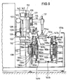
- Fig. 3
- einen Ausschnitt aus Fig. 2 in größerem Maßstab,
- Fig. 4
- im Schema die Anordnung von den Transport und den Antrieb der Objekte bewirkenden Elementen,
- Fig. 5
- in schematischer Darstellung ein Detail der Einrichtung für den Transport der Objekte,
- Fig. 6
- eine der Fig. 5 entsprechende Darstellung eines Details für den Antrieb der Objekte
- Fig. 7a-i
- den Ablauf des Druckvorganges,
- Fig. 8
- eine der Fig. 1 entsprechende Darstellung einer zweiten Ausführungsform
- Fig. 9
- eine der Fig. 2 entsprechende Darstellung dieser zweiten Ausführungsform,
- Fig. 10
- eine der Fig. 4 entsprechende Darstellung der zweiten Ausführungsform,
- Fig. 11a-i
- den Ablauf des Druckvorganges entsprechend der zweiten Ausführungsform
- Fig. 1
- the front view of a screen printing machine for printing objects,
- Fig. 2
- the associated side view,
- Fig. 3
- 3 shows a detail from FIG. 2 on a larger scale,
- Fig. 4
- in the diagram the arrangement of the elements causing the transport and the drive of the objects,
- Fig. 5
- a schematic representation of a detail of the device for the transport of the objects,
- Fig. 6
- a representation corresponding to FIG. 5 of a detail for the drive of the objects
- 7a-i
- the sequence of the printing process,
- Fig. 8
- 1 corresponding representation of a second embodiment
- Fig. 9
- 1 corresponding representation of this second embodiment,
- Fig. 10
- 4 corresponding representation of the second embodiment,
- 11a-i
- the sequence of the printing process according to the second embodiment
Die Siebdruckmaschine 10 ist ferner im Bereich der äußeren Druckstationen I und IV mit vertikalen Führungen 21 versehen, die unmittelbar am Maschinenrahmen 19 angebracht sind. An jeder dieser Führungen 21 ist ein Schlitten 20 geführt. An beiden Schlitten 20 ist ein langgestreckter Träger 29 befestigt, an dem sämtliche Rakeln 14a, 14b, 14c und 14d über Kragarme 31 angebracht sind.The
An seiner den Rakeln abgekehrten Seite ist am Träger 29 eine im wesentlichen horizontale Schiene 34 befestigt, an welcher oberseitig und unterseitig zwei Rollenpaare 36 anliegen, die, wie insbesondere Fig. 2 zeigt, jeweils an den beiden Schlitten 25 angebracht sind, die entlang den Führungen 23 auf- und abbewegbar sind.On its side facing away from the squeegees, an essentially
Die Hin- und Herbewegungen des Basisschlittens 16 in Richtung der Pfeile 17, 18 werden durch einen NC-Motor 38 bewirkt, der ein Zahnriemenrad 40 antreibt, welches mit einem Zahnriemen 42 in Eingriff ist, der auch über ein zweites Zahnriemenrad 49 geführt ist. Der Zahnriemen 42 ist mit dem Basisschlitten 16 verbunden, so daß letzterer und mit ihm die Führungen 23 sowie die über den Schlitten 25 und die Träger 27 mit dem Basisschlitten 16 verbundenen Siebdruckschablonen 14a-14d durch entsprechende Betätigung des NC-Motors 38 in Richtung der Pfeile 17, 18 hin- und herbewegt werden können. Die vertikalen Bewegungen der Druckwerke werden durch einen NC-Motor 22 bewirkt, der eine Welle 24 antreibt, auf welcher zwei Zahnriemenräder 26 befestigt sind, die jeweils mit einem Zahnriemen 28 in Eingriff sind. Oberhalb der vertikalen Führungen 21 ist eine weitere Welle 30 am Maschinenrahmen gelagert, an welcher zwei Zahnriemenräder 32 befestigt sind, von denen jede zur Führung eines der Zahnriemen 28 dient. Jeder der beiden Zahnriemen 28 ist mit einem der beiden Schlitten 25 verbunden, so daß mittels Betätigung des NC-Motors 22 der Träger 27 für die Siebdruckschablonen 12a-12d und damit synchron über die Verbindung zwischen Schiene 34 und Rollenpaaren 36 auch der Träger 29 mit den daran angebrachten Rakeln 14a-14d bewegt werden, wobei der Träger 29 über die Schlitten 20 an den seitlich angeordneten Führungen 21 geführt wird. Bei dem in den Figuren 1 und 2 dargestellen Ausführungsbeispiel nehmen die Rakeln an den Hin- und Herbewegungen in Richtung der Pfeile 17 und 18 nicht teil, wobei aufgrund der Verbindung über die Schiene 34 und die Rollenpaare 36 eine Relativbewegung zwischen der die Rakel tragenden Anordnung und der die Siebdruckschablonen tragenden Anordnung ermöglicht wird.The back and forth movements of the
Unterhalb der Siebdruckstationen I - IV befindet sich eine Transportbahn, entlang welcher die zu bedruckenden Objekte 39 schrittweise durch die einzelnen Behandlungs- und Druckstationen I - IV hindurchgeführt werden. Da die Siebdruckmaschine mit vier Druckstationen versehen ist, werden normalerweise auf dem jeweiligen Objekt aufeinanderfolgend vier Druckbilder aufgebracht, die sich zu einem Gesamtdruckbild ergänzen können. Es ist aber auch möglich, beispielsweise auf demselben Flächenbereich des Objektes nacheinander, beispielsweise in den Stationen I und II, zwei Druckbilder aufzubringen, die sich zu einem Gesamtdruckbild ergänzen, und z.B. in den Druckstationen III und IV zwei weitere Druckbilder, die sich zu einem Gesamtdruckbild ergänzen, auf einem anderen Flächenbereich des Objektes aufzubringen. Die jeweilige Art des Aufbringens der einzelnen Druckbilder und die möglichen Kombinationen sind jedem Fachmann geläufig, so daß sie hier keiner besonderen Erläuterung bedürfen. In Transportrichtung 18 der Objekte kann hinter jeder Druckstation eine Einrichtung angebracht sein, mittels welcher die soeben aufgebrachte Druckfarbe getrocknet werden kann. In vielen Fällen handelt es sich dabei um UV-Strahler. Auch diese Dinge sind jedem Fachmann geläufig, so daß sie nicht näher erläutert zu werden brauchen. Aus Gründen der Übersichtlichkeit sind diese UV-Strahler - oder andere Trocknungseinrichtungen - in der Zeichnung nicht dargestellt.Below the screen printing stations I - IV there is a transport path along which the
Jedes Objekt wird während seines Transports durch die Druckmaschine 10 von einer Halterung getragen. Insgesamt sind zwei Halterungen vorhanden, die unabhängig voneinander transportiert und rotiert werden.Each object is carried by a bracket as it is transported through the
Da die in der Zeichnung als Ausführungsbeispiel dargestellte Druckmaschine 10 zum Bedrucken von flaschenförmigen Objekten dient, die an beiden Enden gehalten werden, besteht jede Halterung aus zwei Halterungsteilen 43a, 43b bzw. 44a, 44b, von denen das Halterungsteil 43a bzw. 44a in üblicher Weise den Bodenabschnitt des Objektes 39 aufnimmt, wohingegen das dornartige ausgebildete Halterungsteil 43b bzw. 44b in den Hals des flaschenförmigen Objektes eingreift.Since the
Die Transportbahn für die Halterungen 43a, 43b und 44a, 44b und die von diesen getragenen Objekte wird durch ein umlaufendes Schienenpaar 46a, 46b definiert, an welchem die Halterungen geführt sind.The transport path for the
Die Halterungsteile 43a, 43b; 44a, 44b werden von entsprechend der Funktion der Halterungsteile paarweise zusammenwirkenden Transportwagen 48a, 48b bzw. 50a, 50b getragen. So sind die Halterungsteile 43a, 43b an den Wagen 48a bzw. 48b angebracht. Die Halterungsteile 44a, 44b werden von den Wagen 50a bzw. 50b getragen. Jeder der Wagen ist mit zwei paarweise angeordneten Rollen 52a, 52b versehen, die jeweils in einem der Höhe der jeweiligen Schiene 46a bzw. 46b entsprechenden Abstand voneinander angeordnet sind und an der jeweiligen Schiene 46a. 46b anliegend zur Führung des jeweiligen Wagens an der Schiene dienen.The
Die beiden Schienen 46a bzw. 46b sind in vertikaler Ebene umlaufend angeordnet, so daß ein oberer, im wesentlichen horizontaler Transportbahnabschnitt 53a und ein vertikal darunter befindlicher, dazu im wesentlichen paralleler unterer Transportbahnabschnitt 53b vorhanden und beide Transportbahnabschnitte 53a, 53b an ihren einander zugekehrten Enden durch jeweils einen etwa halbkreisförmigen Transportbahnabschnitt 53c bzw. 53d miteinander verbunden sind. In jedem dieser beiden halbkreisförmigen Führungsbahnabschnitte 53c, 53d ist ein jeweils dazu koaxialer im wesentlichen horizontal verlaufender Wellensatz 54, 55 angeordnet. Dabei ist die, bezogen auf die Darstellung der Fig. 1, der linke Wellensatz 54 dem Wagenpaar 48a, 48b zugeordnet, wohingegen der rechte Wellensatz 55 dem Wagenpaar 50a, 50b zugeordnet ist.The two
Für den Transport der Halterung 43a, 43b ist der Wellensatz 54 mit einer Welle 57 versehen, auf welcher eine koaxiale Welle 56 drehbar gelagert ist, mit der das Zahnriemenrad 58 fest verbunden ist. Das Zahnriemenrad 58 wird über einen Zahnriemen 60 von einem NC-Motor 61 angetrieben. Auf der Welle 56 sind ferner zwei Zahnriemenräder 62a, 62b fest angebracht, die jeweils einen Zahnriemen 64a, 64b antreiben. Jeder dieser Zahnriemen 64a, 64b ist jeweils über ein Zahnriemenrad 66a, 66b, welches lose auf der rechten Welle 55 angeordnet ist, derart geführt, daß er parallel zu den Schienen 46a, 46b verläuft.For the transport of the
Der über die Zahnriemenräder 62a, 66a laufende endlose Zahnriemen 64a ist mit dem Wagen 48a verbunden, welcher das Halterungsteil 43a trägt. Der über die Zahnriemenräder 62b und 66b laufende endlose Zahnriemen 64b ist mit dem Wagen 48b für das Halterungsteil 43b verbunden. Über die Betätigung des NC-Motors 61 kann somit der Transport des von den Halterungsteilen 43a, 43b getragenen Objektes entlang der durch die Schienen 46a, 46b definierten Führungsbahn bewirkt und gesteuert werden.The endless
Da der zu bedruckende Abschnitt des flaschenförmigen Objektes während des Druckvorganges an der Siebdruckschablone abgerollt werden muß, ist zur Übertragung der dazu erforderlichen Bewegungen auf das Objekt ein Zahnriemenrad 70 mit der Welle 57 fest verbunden, welches über einen Zahnriemen 72 von einem NC-Motor 74 antreibbar ist. Weiterhin sind mit der Welle 57 zwei Zahnriemenräder 68a, 68b fest verbunden. Jedes dieser beiden Zahnriemenräder treibt jeweils einen Zahnriemen 71a, 71b an, der zudem über ein lose auf der rechten Welle 55 angeordnetes Zahnriemenrad 75a bzw. 75b geführt ist. Der endlose Zahnriemen 71a ist dem Wagen 48a zugeordnet und durch diesen hindurchgeführt. Dazu ist der Wagen 48a mit zwei Führungsrollen 83a, 83b versehen, über die der Zahnriemen 71a mit seiner glatten Seite läuft. Ein am Wagen angebrachtes Zahnriemenrad 85, welches vom Zahnriemen 71a angetrieben wird, ist fest mit einer Welle 84 verbunden, welche das Halterungsteil 43a trägt. Demzufolge hat eine Betätigung des NC-Motors 74 eine entsprechende Drehbewegung des Halterungsteiles 43a und damit des von diesem getragenen Objektes zur Folge. Eine derartige Rotationsbewegung kann auch durch bloße Verschiebung des Wagens 48a entlang seiner durch die Schiene 46a bestimmten Transportbahn bei stillstehendem Zahnriemen 71a bewirkt werden. Bei sich entlang der Führungsbahn bewegendem Wagen würde somit die Rotationsbewegung des vom Halterungsteil 43a getragenen Objektes resultieren aus dieser Transportbewegung und einer gegebenenfalls gleichzeitig erfolgenden Bewegung des Zahnriemenrades 71a.Since the section of the bottle-shaped object to be printed must be unrolled on the screen printing stencil during the printing process, a
Die vorstehend beschriebene Anordnung der Teile und deren Zusammenwirken gelten in entsprechender Weise für den Zahnriemen 71b und den das zugehörige Halterungsteil 43b tragenden Wagen 48b. Aufgrund der Tatsache, daß die Zahnriemenräder 62a und 62b bzw. 68a und 68b jeweils starr miteinander und mit dem jeweiligen Antriebszahnriemenrad 58 bzw. 70 fest verbunden sind, ist eine absolute Synchronität der Bewegungen der beiden Wagen 48a, 48b und damit der das Objekt tragenden Halterungsteile 43a, 43b gewährleistet.The arrangement of the parts described above and their interaction apply in a corresponding manner to the
Die beiden in der Zeichnung in unterer Position dargestellten Wagen 50a, 50b der Halterung 44a, 44b werden in entsprechender Weise über den in Fig. 1 der Zeichnung rechts befindlichen Wellensatz 55 angetrieben, dem ebenfalls zwei NC-Motoren zugeordnet sind, von denen der NC-Motor 86 für den Transport der beiden Wagen 50a, 50b entlang der durch die beiden Schienen 46a, 46b definierten Führungsbahn dient und der NC-Motor 87 den Antrieb der Halterungsteile 44a, 44b zwecks Rotation des von diesen getragenen Objektes bewirkt. Auf der Welle 77 des Wellensatzes 55 ist eine koaxiale Welle 78 drehbar gelagert, mit der mehrere Zahnriemenräder fest verbunden sind. Das Zahnriemenrad 90 wird über einen Zahnriemen 67 vom NC-Motor 86 angetrieben. Auf der Welle 78 sind ferner zwei Zahnriemenräder 88a, 88b fest angebracht, die jeweils einen Zahnriemen 89a, 89b antreiben. Jeder dieser Zahnriemen 89a, 89b ist über ein Zahnriemenrad 91a, 91b, welches lose auf der linken Welle 57 gelagert ist, derart geführt, daß er parallel zu den Schienen 46a, 46b verläuft. Beide Zahnriemen 89a, 89b sind jeweils mit einem der Wagen 50a, 50b verbunden, um diesen entlang der durch die Schienen 46a, 46b definierten Führungsbahn zu transportieren.The two
Mit der Welle 77 ist ein Zahnriemenrad 92 fest verbunden, welches über einen Zahnriemen 73 vom NC-Motor 87 antreibbar ist. Weiterhin sind mit der Welle 77 zwei Zahnriemenräder 94a, 94b fest verbunden. Jedes dieser beiden Zahnriemenräder treibt einen Zahnriemen 95a, 95b an, der zudem über ein lose auf der linken Welle 57 angeordnetes Zahnriemenrad 96a, 96b geführt ist. Der Zahnriemen 95a ist dem Wagen 50a zugeordnet und in der bereits im Zusammenhang mit dem Zahnriemen 71a und dem Wagen 48a beschriebenen Weise durch den Wagen 50a hindurchgeführt. Der Zahnriemen 95b ist in entsprechender Weise dem Wagen 50b zugeordnet. Beide Zahnriemen dienen dazu, die beim Bedrucken oder sonstigen Behandlungen erforderliche Rotationsbewegung des von der Halterung 44a, 44b getragenen Objektes zu bewirken.A
Beide Wellensätze 54, 55 tragen zudem unter Zwischenschaltung geeigneter Lager stationäre Träger 35. An den axialen Enden beider Träger, die an der Rotation der Wellen 58, 78 der beiden Wellensätze 54, 55 nicht teilnehmen, sind Haltemittel 63a, 63b angebracht, die die umlaufenden Führungsschienen 46a, 46b tragen.Both shaft sets 54, 55 also carry
Es war bereits erwähnt worden, daß beim Bedrucken eines Objektes, dessen zu bedruckender Bereich bezüglich seiner Querschnittsform von der Kreisform oder der Form eines Kreisbogens abweicht, das Objekt in Abhängigkeit von der Querschnittsform des zu bedruckenden Bereiches eine Verschiebung quer zu seiner Längsachse erfährt, damit gewährleistet ist, das der Bereich der Oberfläche des Objektes, auf welchen im Verlauf des Druckvorganges jeweils die Druckfarbe durch die Rakel übertragen wird - im folgenden "Transferbereich" genannt - im wesentlichen tangential zur Siebdruckschablone verläuft und die Rakel immer im wesentlichen senkrecht über der Mittelachse des Transferbereiches steht und somit die Verlängerung des vertikalen Radius' dieses Transferbereiches darstellen sollte. Da bei einem beispielsweise elliptisch geformten Körper in Umfangsrichtung der zu bedruckenden Oberfläche die einzelnen Abschnitte der Oberfläche unterschiedliche Krümmungen und damit unterschiedliche Mittelachsen aufweisen, kann ein ständiges Verschieben des Objektes senkrecht zu seiner Längsachse erforderlich sein, um die vorgenannten Bedingungen - tangentialer Verlauf des Transferbereiches zur Siebdruckschablone bzw. Positionierung der Rakel im wesentlichen senkrecht über der Mittelachse des Transferbereiches - zu erfüllen.It had already been mentioned that when printing on an object whose area to be printed deviates in cross-sectional shape from the circular shape or the shape of a circular arc, the object experiences a displacement transversely to its longitudinal axis depending on the cross-sectional shape of the area to be printed, thus ensuring is that the area of the surface of the object on which the printing ink is transferred through the doctor blade in the course of the printing process - hereinafter referred to as the "transfer area" - is essentially tangential to the screen printing stencil and the doctor blade is always essentially perpendicular to the central axis of the transfer area stands and should therefore represent the extension of the vertical radius of this transfer area. Since, for example, in the case of an elliptically shaped body in the circumferential direction of the surface to be printed, the individual sections of the surface have different curvatures and thus different central axes, constant displacement of the object perpendicular to its longitudinal axis may be necessary in order to meet the aforementioned conditions - tangential course of the transfer area to the screen printing stencil or positioning of the squeegee substantially perpendicular to the Central axis of the transfer area - to be met.
In den Figuren 7a - 7i ist der Ablauf des Bedruckens eines im Querschnitt elliptischen Objektes über den gesamten Umfang von 360° dargestellt, wobei die Siebdruckschablone 12a in X-Richtung hin- und herverschiebbar und die Rakel 14a in X-Richtung stationär angeordnet ist. Der Einfachheit halber ist lediglich die Kontur des Objektes 39 dargestellt, welches von den nicht dargestellten Halterungsteilen 43a, 43b getragen wird, die über die Zahnriemen 64a, 64b durch den programmgesteuerten NC-Motor 61 in die Position gemäß Fig. 7a transportiert wurden, die die Positionen der zusammenwirkenden Teile am Anfang des Druckvorganges zeigt. Die sowohl in Richtung der X-Achse als auch in Richtung der Y-Achse hin- und herbewegbare Siebdruckschablone 12a nimmt ihre Ausgangsposition für den Druckvorgang ein, die mit ihrer linken Endposition zusammenfällt. Das Objekt 39 nimmt eine Lage ein, bei welcher seine längere Querschnittsachse horizontal verläuft und die Rakel 14a sich vertikal über der kürzeren Querschnittsachse des Objektes in Verlängerung derselben und somit vertikal über der Längsachse 81 des Querschnittes befindet, der in dieser Position der Teile zugleich auch die Längsachse des Transferbereiches ist. Das heißt, daß in dieser Position der Teile die Längsachse 81 des Querschnittes und die Längsachse des Transferbereiches zusammenfallen. Der Abstand zwischen der Längsachse 81 von der Siebdruckschablone 12a ist in Fig. 7a mit "b" bezeichnet.FIGS. 7a-7i show the process of printing an object which is elliptical in cross-section over the entire circumference of 360 °, the
Mit Beginn des Druckvorganges wird das Objekt 39 über die Zahnriemen 71a, 71b durch den programmgesteuerten NC-Motor 74 in Richtung des Pfeiles 47 um seine Längsachse 81 verschwenkt, wobei die Siebdruckschablone 12a durch den programmgesteuerten NC-Motor 38 nach rechts in Richtung der X-Achse verschoben und gleichzeitig mit der Rakel 14a durch den programmgesteuerten NC-Motor 22 in Richtung der Y-Achse angehoben wird, um so der Tatsache Rechnung zu tragen, daß aufgrund der elliptischen Querschnittsform des Objektes 39 bzw. des zu bedruckenden Bereiches desselben der Transferbereich an der Mantelfläche des Objektes, der durch die Rakel jeweils mit Druckfarbe versehen wird, im Zuge der Schwenkbewegung des Objektes sich kontinuierlich nach oben bewegt. Figur 7b zeigt ein Zwischenstadium im Verlauf des Druckvorganges, bei welchem die beiden Achsen des Querschnittes schräg verlaufen. Während der Schwenkbewegung, die das Objekt 39 bis dahin erfahren hat, ist die Mittelachse 81 um die Wegstrecke l in Richtung der X-Achse gegenüber der Rakel 14a verschoben worden, die in Richtung der X-Achse stationär ist. Die dazu notwendige Verschiebung der Halterung 43a, 43b in Richtung der X-Achse wird ebenfalls durch den entsprechend programmgesteuerten NC-Motors 61 bewirkt, der die Zahnriemen 64a, 64b5 antreibt. Der Abstand zwischen Mittelachse 81 und Siebdruckschablone in der zwischenposition gemäß Fig. 7b ist mit "h" bezeichnet.At the beginning of the printing process, the
Fig. 7c zeigt die relativen Positionen der zusammenwirkenden Teile zu einem Zeitpunkt, zu welchem die längere Achse des Objektquerschnittes vertikal verläuft und die Rakel 14a sich in Verlängerung dieser Achse senkrecht über dem Querschnittsmittelpunkt befindet, so daß Längsachse 81 des Objektes und Längsachse des Transferbereiches wieder zusammenfallen. Somit sind im Zuge der Schwenkbewegung aus der Position gemäß Fig. 7b in die der Fig. 7c die Wagen 48a, 48b mit den daran befindlichen Halterungen 43a, 43b wieder um den Weg l in die Ausgangsposition gemäß Fig. 7a zurückbewegt worden. Zusätzlich ist das aus Siebdruckschablone 12a und Rakel 14a bestehende Druckwerk weiter auf den Abstand a angehoben worden, um der Tatsache Rechnung zu tragen, daß der Transferbereich der Position gemäß Fig. 7c höher liegt als in der Position gemäß Fig. 7b.7c shows the relative positions of the interacting parts at a point in time at which the longer axis of the object cross-section runs vertically and the
Im Zuge der weiteren Schwenkbewegung in die Position gemäß Fig. 7d erfolgt eine erneute Lateralverschiebung des Objektes 39, um die vorstehend beschriebene Position der Rakel 14a zum jeweils zu bedruckenden Flächenbereich des Objektes aufrechtzuerhalten, wobei jedoch diesmal die Verschiebung in entgegengesetzter Richtung, also nach links erfolgt. Die in Fig. 7d dargestellte Wegstrecke l entspricht der Wegstrecke l der Fig. 7b, da in beiden Fällen das Objekt im wesentlichen die gleiche Winkellage zur Siebdruckschablone, jedoch jeweils in die entgegengesetzte Richtung weisend, einnimmt. Entsprechend der Höhenlage des Transferbereiches ist in Fig. 7d das Druckwerk gegenüber der Position gemäß Fig. 7c etwas abgesenkt worden.In the course of the further pivoting movement into the position according to FIG. 7d, the
Im Zuge der Schwenkbewegung des Objektes aus der Position gemäß 7d in die gemäß Fig. 7e, in welcher das Objekt 39 eine um 180° verschwenkte Position im Vergleich zu der der Fig. 7a einnimmt, werden die Wagen 48a, 48b wieder in die Ausgangslage gemäß Fig. 7a zurückbewegt, so daß bei Erreichen der Position gemäß Fig. 7e die Rakel sich wieder über der Längsachse des Objektes und in Verlängerung der kürzeren Querschnittsachse desselben befindet und die Längsachse des Objektes und die Längsachse des Transferbereiches wieder zusammenfallen. Gleichzeitig ist während dieser Phase der Schwenkbewegung das Druckwerk dem nach unten sich bewegenden Transferbereich folgend abgesenkt worden.In the course of the pivoting movement of the object from the position according to FIG. 7d into that according to FIG. 7e, in which the
Die Fig. 7f - 7i zeigen den Ablauf der Bewegungen beim Bedrucken der anderen Seite des Objektes 39. Diese Bewegungen entsprechen denen der Fig. 7a - 7e, so daß am Ende alle Teile wieder die Ausgangsposition gemäß Fig. 7a einnehmen. Dies ist jedoch bei diesem Ausführungsbeispiel darauf zurückzuführen, daß das Objekt 39 über einen Bereich von 360° bedruckt wird. Es ist selbstverständlich auch möglich und üblich, das Objekt nur auf einem Teil seines Umfanges zu bedrucken. In diesem Fall könnten die Schwenkbewegung des Objektes, die vertikalen Bewegungen der Siebdruckschablone und der Rakel sowie die laterale Verschiebung der Wagen 48a, 48b nur in dem Ausmaß, den das Druckbild erfordert, durchgeführt werden. So könnte beispielsweise bei Bedruckung des Objektes auf einer Hälfte seines Umfanges die Bewegungsabläufe mit Erreichen der Position gemäß Fig. 7e beendet sein.7f-7i show the sequence of the movements when printing on the other side of the
Wenngleich die zu bedruckenden Bereiche der in beiden Ausführungsbeispielen dargestellten Objekte keinen kreisförmigen Querschnitt aufweisen, sind sie insoweit regelmäßig ausgebildet als der jeweils zu bedruckende Bereich einen elliptischen Querschnitt mit zwei Symmetrieachsen aufweist. Die Erfindung ist jedoch keineswegs auf das Bedrucken von Objekten mit einer derartigen regelmäßigen Querschnittsform beschränkt. Es ist möglich, auch solche Objekte zu bedrucken, deren zu bedruckender Bereich einen unregelmäßigen Querschnitt aufweist, beispielsweise eine ebene Fläche einschließt. Ferner können auch solche Objekte bedruckt werden, die beispielsweise einen im wesentlichen quadratischen Querschnitt aufweisen, wobei die Kanten abgerundet und die zwischen zwei benachbarten Kanten befindlichen Bereiche etwas nach außen gewölbt sind. Es wäre aber auch möglich, derartige Objekte mit abgerundeten Kanten dann zu bedrucken, wenn die zwischen zwei benachbarten Kanten befindliche Fläche völlig eben, also nicht gekrümmt ist.Although the areas to be printed on the objects shown in both exemplary embodiments do not have a circular cross section, they are regularly designed insofar as the area to be printed in each case has an elliptical cross section with two axes of symmetry. However, the invention is in no way limited to the printing of objects with such a regular cross-sectional shape. It is also possible to print objects whose area to be printed has an irregular cross section, for example including a flat surface. Furthermore, it is also possible to print objects which, for example, have an essentially square cross section, the edges being rounded and the regions located between two adjacent edges being slightly curved outwards. However, it would also be possible to print objects of this type with rounded edges if the surface located between two adjacent edges is completely flat, that is to say not curved.
Beim Bedrucken von Flächen, die im Querschnitt kreisförmig sind oder den Abschnitt eines Kreises bilden, sind die vorbeschriebenen Bewegungen des Objektes in Richtung der X-Achse und der Y-Achse nicht erforderlich.When printing on surfaces that are circular in cross-section or form the section of a circle, the above-described movements of the object in the direction of the X-axis and the Y-axis are not necessary.
Bei der Ausführungsform gemäß Fig. 1 - 4 sind die Station VI, in welcher die zu bedruckende Flasche in die Halterung 43a, 43b bzw. 44a, 44b gegeben wird, und die Station VII, in welcher die bedruckte Flasche aus der jeweiligen Halterung herausgenommen wird, dem unteren Abschnitt 53b der Transportbahn zugeordnet. Das Einführen der zu bedruckenden Flasche in die jeweils in der Aufnahmestation VI befindlichen Halterung erfolgt über einen Greifer 79a, der dreidimensional bewegbar ist und die durch einen Förderer 97a herantransportierte Flasche aufnimmt und durch einander überlagernde Schwenkbewegungen die Flasche aus der vertikalen in eine horizontale Position und dabei zugleich in die Aufnahmestation VI bringt, in welcher sie von den beiden Teilen der jeweils dort befindlichen Halterung aufgenommen wird. Es ist bekannt, die beiden das Objekt tragenden Halterungsteile so anzubringen, daß der zwischen ihnen befindliche Abstand verändert werden kann, damit die beiden Halterungsteile das zu bedruckende Objekte aufnehmen und halten können, um später das bedruckte Objekt freigeben zu können. Bei den in der Zeichnung dargestellten Ausführungsbeispielen ist lediglich das mit dem halsseitigen Ende des flaschenförmigen Objektes 39 zusammenwirkende Halterungsteil 43a, 43b parallel zur Längsachse des von den Halterungsteilen getragenen Objektes verschiebbar im jeweils zugehörigen Wagen 48b, 50b angeordnet. Dazu ist das Halterungsteil 43b, 44b mit einer Kurvenrolle 101 versehen, die in der Aufnahmestation VI und in der Entnahmestation VII mit einem Kurvenabschnitt 103 zusammenwirkt, der parallel zur Transportrichtung des Objektes im Bereich der vorgenannten Stationen verläuft. Der Kurvenabschnitt 103 ist durch eine pneumatische Zylinder-Kolben-Anordnugn 105 quer zur Transportrichtung verschiebbar. Im Verlauf der Bewegung der Halterungsteile in Richtung des Pfeiles 17 (Fig. 1) in die Entnahmestation VII läuft die jeweils am Halterungsteil 43b bzw. 44b befindliche Kurvenrolle 101 in die Kurve des Kurvenabschnittes 103 ein. Nach Erreichen der Entnahmestation IV wird der Greifer 79b entlang der Schiene 99b in die, bezogen auf die Darstellung der Fig. 1, linke Endposition verfahren und in die Entnahmestation verschwenkt, um das dort befindliche, noch von den Halterungsteilen getragene Objekt zu erfassen. Daraufhin wird über eine entsprechende Betätigung der Zylinder-Kolben-Anordnung 105 das Halterungsteil 44b von dem Halterungsteil 44a um eine Wegstrecke wegbewegt, die ausreicht, um das nunmehr vom Greifer 79b getragene Objekt an seinem halsseitigen Ende freizugeben. Der Greifer führt daraufhin eine kurze Bewegung in Richtung auf das halsseitige Halterungsteil 44b aus, um das Objeket außer Eingriff mit der Bodenaufnahme 44a zu bringen. Alsdann kann der Greifer mit dem Objekt entlang der Schiene 99b in Richtung auf den Förderer 79b verschoben und so verschwenkt werden, daß er das bedruckte Objeket in senkrechter Position auf den Förderer 79b aufsetzt, wie dies in Fig. 1 dargestellt ist. Die Halterung 44a, 44b kann dann in die Aufnahmestation VI vorbewegt werden, wobei das Halterungsteil 44b seine Position beibehält, in welcher es seinen größeren Abstand vom Halterungsteil 44a aufweist, so daß nach Erreichen der Aufnahmestation VI der Greifer 79a ein Objekt, das er zuvor vom Förderer 97a abgenommen hat, in horizontaler Lage zunächst zwischen die beiden Halterungsteile 44a, 44b bringt und anschließend durch eine entsprechende Bewegung parallel zur Längsachse des Objektes dessen Bodenbereich in die Halterung 44a einschiebt. Alsdann wird durch die in der Aufnahmestation VI befindliche Zylinder-Kolben-Einrichtung 105 der dort befindliche Kurvenabschnitt 103 unter Mitnahme der sich in der Kurve dieses Kurvenabschnittes befindlichen Kurvenrolle 101 in Richtung auf das Halterungsteil 44a verschoben mit dem Ergebnis, daß das Halterungsteil 44b in den Hals des Objektes 39 eingreift, so daß letzteres nunmehr von den beiden Halterungsteilen getragen wird. Der Greifer 79a kann nunmehr das Halterungsteil freigeben und in die Position zur Aufnahme des nächsten Objektes zurückbewegt werden.1-4 are the station VI, in which the bottle to be printed is placed in the
Im Zuge des schrittweisen Vortransportes des nunmehr von der Halterung 44a, 44b getragenen Objektes im unteren Abschnitt 53b der Transportbahn in Richtung des Pfeiles 18 gerät die Kurvenrolle 101 außer Eingriff mit dem Kurvenabschnitt 103 Nach Erreichen des oberen Abschnittes 53a der Transportbahn in Richtung des Pfeiles 18 kann das Objekt vor Erreichen der ersten Druckstation I irgendwelchen zusätzlichen Behandlungen unterzogen werden. Die Objekt können entstaubt, beflammt und in Umfangsrichtung ausgerichtet werden. Nach der Vorbehandlung wird das Objekt dann in die erste Druckstation I gebracht, in der die Teile unmittelbar vor Druckbeginn die im Zusammenhang mit Fig. 7a beschriebenen Positionen einnehmen. Nach Beendigung des Druckvorganges in der Druckstation I erfolgt dann der Transport in die Druckstation II, in welcher das nächste Druckbild aufgebracht wird. Nach Aufbringen des letzten Druckbildes in der Station IV gelangt dann das Objekt nach Passieren des Abschnittes 53c der Transportbahn wiederum in den unteren Abschnitt 53b und dort in die Entnahmestation VII, in welcher das Objekt in der bereits beschriebenen Weise durch den Greifer 79b aus der Halterung herausgenommen wird.In the course of the step-by-step advance transport of the object now carried by the
Aufgrund der Tatsache, daß beide Halterungen 43a, 43b und 44a, 44b unabhängig voneinander entlang der Transportbahn bewegt werden, besteht die Möglichkeit, beispielsweise nach Aufbringen des letzten Druckbildes das Objekt sofort in die Entnahmestation VII zu transportierten und nach Entnahme des bedruckten Objektes aus der Halterung diese sofort in die Aufnahmestation VI vorzubewegen, um dort das nächste Objekt aufzunehmen. Es besteht weiterhin die Möglichkeit, in den gegebenenfalls zwischen Aufnahmestation VI und Druckstation I befindlichen Behandlungsstationen alle gewünschten Behandlungen durchzuführen, ohne daß dies durch den Transport der anderen Halterung(en) behindert oder verzögert würde. Dadurch wird gegenüber bekannten Maschinen eine erhebliche Produktivitätssteigerung erzielt.Due to the fact that both
Das in den Figuren 8 und 9 dargestellte Ausführungsbeispiel stimmt weitgehend mit dem Ausführungsbeispiel gemäß den Fig. 1 - 4 überein, so daß gleiche oder einander entsprechende Teile mit gleichen Bezugszeichen versehen sind, die jedoch in den Fig. 8 - 11 um 100 größer sind. Drucktechnisch besteht der wesentliche Unterschied zwischen beiden Ausführungsbeispielen darin, daß die Siebdruckschablonen 112a, 112b, 112c, 112d, 112e der fünf Druckwerke insoweit stationär angeordnet, als sie während des Druckvorganges keine Bewegungen parallel zu ihrer Hauptebene, also in Richtung der X-Achse, ausführen. Dafür sind die Rakeln 114a, 114b, 114c, 114d, 114e im wesentlichen parallel zur Hauptebene der jeweils zugehörigen Siebdruckschablone und senkrecht zur Längsachse des zu bedruckenden Objektes hin- und herverschiebbar angeordnet, um die für den Druckvorgang erforderliche Relativbewegung zwischen Siebdruckschablone und zugehöriger Rakel zu bewirken.The exemplary embodiment shown in FIGS. 8 and 9 largely coincides with the exemplary embodiment according to FIGS. 1-4, so that the same or corresponding parts are provided with the same reference numerals, but are 100 larger in FIGS. 8-11. In terms of printing technology, the main difference between the two exemplary embodiments is that the
Auch bei diesem Ausführungsbeispiel ist jedes der aus Siebdruckschablone und Rakel bestehenden Druckwerke vertikal auf- und abbewegbar angeordnet, um bei Objekten, deren zu bedruckende Oberfläche im Querschnitt vom Verlaufe eines Kreises oder Kreisabschnittes abweicht, der im Zuge der vom Objekt ausgeführten Schwenkbewegung sich ändernden Höhenlage des jeweils an der Siebdruckschablone anliegenden Transferbereiches folgen zu können. Zu diesem Zweck ist ein NC-Motor 122 vorhanden, der eine Welle 124 antreibt, auf welcher zwei Zahnriemenräder 126 befestigt sind, die jeweils mit einem vertikalen Zahnriemen 128 in Eingriff sind. Oberhalb der beiden Zahnriemenräder 126 sind mit einem Abstand von diesen zwei Zahnriemenräder 132 angeordnet, von denen jedes zur Führung eines der Zahnriemen 128 dient. Jeder der beiden Zahnriemen 128 ist über jeweils eine Traverse 109 mit einem Schlitten 125 verbunden, der an vertikalen Führungen 121 geführt ist, die am Maschinenrahmen 119 befestigt sind. An diesem Schlitten 125 sind sämtliche Siebdruckschablonen 112a-112e angebracht. Ferner ist der Schlitten 125 mit zwei in einem Abstand voneinander verlaufenden im wesentlichen horizontalen Führungen 115 versehen, an welchen ein Schlitten 116 im wesentlichen horizontal hin- und herverschiebbar ist, der sämtliche Rakeln 114a - 114e über Kragarme 131 trägt. Die Hin- und Herbewegungen des Rakelschlittens 116 werden durch einen NC-Motor 138 bewirkt, der über eine aus zwei teleskopartig zusammenwirkenden Wellenabschnitte 141, 145 bestehende Welle ein Zahnriemenrad 140 antreibt. Ein Zahnriemen 142 ist um dieses Zahnriemenrad 140 und um ein zweites in einem horizontalen Abstand angeordnetes Zahnriemenrad 149 geführt. Die beiden Zahnriemenräder 140 und 149 sind auf einem Träger 151 angeordnet, der rückseitig am Schlitten 125 angebracht ist. Mithin nehmen die beiden Zahnriemenräder 140, 149 und der in horizontaler Ebene hin- und herbewegbare Zahnriemen 142 an den Auf- und Abbewegungen des Schlitten 125 teil, wobei durch das teleskopartige Zusammenwirken der beiden Wellenabschnitte 141, 145 die Änderungen des Abstandes zwischen dem NC-Motor 138 und dem Zahnriemenrad 140 ermöglicht werden. Der Zahnriemen 142 und der an den Führungen 115 geführte Schlitten 116 sind durch wenigstens eine Traverse 159 miteinander verbunden, so daß die in horizontaler Ebene erfolgenden Hin- und Herbewegungen des Schlittens 116 mit den daran befindlichen Rakeln durch den Zahnriemen 142 bewirkt werden.In this exemplary embodiment, too, each of the printing units consisting of screen printing stencil and squeegee is arranged such that it can be moved vertically up and down, in the case of objects whose surface to be printed deviates in cross-section from the course of a circle or segment of a circle, the changing altitude in the course of the pivoting movement carried out by the object to be able to follow the transfer area adjacent to the screen printing template. For this purpose, there is an
Auch bezüglich der Mittel zum Transportieren und Verschwenken der Halterungen für die Objekte 139 und die dazu benötigten Antriebe stimmt die Ausführungsform gemäß den Figuren 8 und 9 mit der gemäß den Figuren 1 und 2 im Prinzip überein. Dazu wird insbesondere auf Fig. 10 verwiesen, die die Anordnung der Wellensätze und der einzelnen von ihnen getragenen Zahnriemenräder mit den Zahnriemen erkennen läßt. Auch in Fig. 10 sind alle Teile, die Teilen des Ausführungsbeispieles gemäß den Fig. 1 - 4 entsprechen, mit den gleichen, jedoch um jeweils um 100 höheren Bezugszeichen versehen. Die Anordnung gemäß Fig. 10 erlaubt einen etwas gedrängteren Aufbau als die Anordnung gemäß Fig. 4.The embodiment according to FIGS. 8 and 9 also corresponds in principle to that according to FIGS. 1 and 2 with regard to the means for transporting and pivoting the holders for the
In den Figuren 11a - 11i ist analog der Darstellung in den Figuren 7a - 7i der Ablauf der Bewegungen der beim Druckvorgang zusammenwirkenden Teile dargestellt, wenn die Siebdruckschablone parallel zur X-Achse stationär und die Rakel parallel zur X-Achse verschiebbar angeordnet ist. Dabei ist es erforderlich, daß das Objekt 139 während des Druckvorganges in Richtung der X-Achse bewegt wird, um die zu bedruckenden Oberflächenbereiche desselben an der Siebdruckschablone abzurollen. Diese Bewegung wird über die das Objekt tragenden Halterungsteile 143a, 143b durch den NC-Motor 161, welcher die beiden Zahnriemen 164a, 164b antreibt, mit denen die beiden Wagen 148a, 148b für die Halterungsteile verbunden sind, auf das Objekt übertragen. Da jedoch auch mit der Vorrichtung gemäß den Figuren 8 und 9 ein Objekt bedruckt wird, dessen zu bedruckende Fläche einen Querschnitt aufweist, der von der Kreisform abweicht, besteht auch hier die Notwendigkeit, zusätzlich das Objekt in Richtung der Y-Achse zu verschieben, um zu erreichen, daß der Transferbereich des Objektes im wesentlichen tangential zur Siebdruckschablone verläuft und die Rakel im wesentlichen senkrecht über der Mittelachse des Transferbereiches steht. Wenn die Rakel im Zuge des Druckvorganges mit konstanter Geschwindigkeit relativ zur in Richtung der X-Achse feststehenden Siebdruckschablone beispielsweise aus der Position gemäß Figur 11a in die Position gemäß Figur 11b bewegt wird, ist es erforderlich, der gleichzeitig erfolgenden Transportbewegung des Objektes in derselben Richtung eine zweite Bewegung zu überlagern. Dazu ist der NC-Motor 161 so programmiert, daß eine resultierende Bewegung bewirkt wird, bei welcher die Rakel bei Erreichen der Position gemäß Figur 11b nicht über der Mittelachse 181 des Querschnittes des zu bedruckenden Objektes, sondern gegenüber diesem Mittelpunkt nach rechts versetzt, bezogen auf die Darstellung der Figur 11b, sich befindet, um die vorgenannte Bedingung zu erfüllen, daß die Rakel sich über dem Mittelpunkt bzw. über der Mittelachse befindet, der bzw. die zum Krümmungsradius des Transferbereiches der Objektoberfläche gehört. Im konkreten Fall bedeutet dies, daß die Bewegung des Objektes zwischen den beiden Positionen der Figuren 11a und 11b gegenüber der in derselben Richtung erfolgenden Bewegung der Rakel etwas nacheilt, und zwar um den Weg l. In Figur 11c befindet sich die Rakel wieder genau über der Mittelachse des Objektquerschnittes, die zu diesem Zeitpunkt auch die Mittelachse des Transferbereiches ist, so daß demzufolge die Bewegungen von Objekt und Rakel in Richtung der X-Achse - wiederum in Abhängigkeit von der Querschnittsform des zu bedruckenden Bereiches - mit unterschiedlichen resultierenden Geschwindigkeiten erfolgen derart, daß in dieser Druckphase die Rakel im Ergebnis etwas langsamer in Richtung der X-Achse bewegt wird als das Objekt. In der nächsten Phase des Druckvorganges, also bei der Bewegung der zusammenwirkenden Teile von der Position gemäß Figur 11c in die der Figur 11d, werden Rakel und Objekt wiederum in Abhängigkeit von der Querschnittsform des in dieser Phase zu bedruckenden Flächenbereiches mit unterschiedlichen Geschwindigkeiten bewegt derart, daß das Objekt um die Wegstrecke l voreilt, die dem Abstand in der X-Achse zwischen der Achse 181, um welche das Objekt gedreht wird, und der Position der Rakel entspricht. In der nächsten Phase des Druckvorganges, an deren Ende die Teile die Positionen gemäß Figur 11e einnehmen, wird wiederum das Objekt im Ergebnis langsamer in Richtung der X-Achse bewegt als die Rakel, so daß am Ende die Rakel über der Rotationsachse 181 des Objektes steht.In FIGS. 11a-11i, analogously to the illustration in FIGS. 7a-7i, the sequence of the movements of the parts interacting during the printing process is shown if the screen printing stencil is stationary parallel to the X-axis and the squeegee is displaceable parallel to the X-axis. It is necessary that the
Die Figuren 11f - 11i zeigen den Ablauf der Bewegungen beim Bedrucken der anderen Seite des Objektes 39. Hier besteht bezüglich des Ablaufs der Bewegungen Übereinstimmung mit dem im Zusammenhang mit den Figuren 11a - 11e beschriebenen Ablauf.FIGS. 11f-11i show the sequence of the movements when printing on the other side of the
Für die Halterungsteile 144a und 144b und das von ihnen getragene Objekt gilt entsprechendes.The same applies to the mounting
Die vertikalen gemeinsamen Bewegungen von Siebdruckschablone und Rakel stimmen mit denen des Ausführungsbeispiels gemäß den Figuren 7a - 7i überein, da auch die Querschnittsformen der Objekte übereinstimmen.The vertical common movements of the screen printing stencil and doctor blade coincide with those of the exemplary embodiment according to FIGS. 7a-7i, since the cross-sectional shapes of the objects also match.
Bei der Ausführungsform gemäß den Figuren 8 und 9 sind die beiden Stationen, in denen die zu bedruckenden Objekte in die Halterungen eingelegt werden bzw. die bedruckten Objekte aus diesen Halterungen herausgenommen werden, dem oberen Abschnitt 53a der Transportbahn zugeordnet, wohingegen im Falle der Ausführungsform gemäß den Figuren 1 und 2, wie bereits erläutert, diese Stationen dem unteren Abschnitt 53b zugeordnet sind. Welche der beiden Möglichkeiten der Vorzug gegeben wird, hängt von den jeweiligen Gegebenheiten ab, z.B. davon, ob in dem Bereich der Transportbahn 53c bzw. 153c noch irgendwelche Vorbehandlungen durchgeführt werden sollen, bevor der erste Bedruckungsvorgang stattfindet. Im übrigen ist bei der Vorrichtung gemäß den Figuren 8 und 9 der ersten Druckstation I im Bereich des oberen Transportbahnabschnittes 153a noch eine Station vorgeschaltet, in welcher die Objekte in Umfangsrichtung ausgerichtet werden.In the embodiment according to FIGS. 8 and 9, the two stations in which the objects to be printed are placed in the holders or the printed objects are removed from these holders are assigned to the
Beim Bedrucken von Objekten, die nach dem Bedruckungsvorgang eine besondere Behandlung zum Trocknen der Druckfarbe erfordern, können beispielsweise die Stationen II und IV der Vorrichtung gemäß den Figuren 8 und 9 durch jeweils eine Trocknungseinrichtung, beispielsweise einen UV-Strahler ersetzt werden, der gegebenenfalls beim Transport der Objekte von der einen Druckstation zur jeweils folgenden Druckstation sich im wesentlichen synchron mit diesen Objekten bewegen kann, wenn dadurch die Produktivität der Maschine erhöht wird.When printing on objects that require special treatment for drying the printing ink after the printing process, for example stations II and IV of the device according to FIGS. 8 and 9 can each be replaced by a drying device, for example a UV lamp, which may be used during transport the objects can move from one printing station to the following printing station essentially synchronously with these objects if the productivity of the machine is increased as a result.
Es ist in Abhängigkeit von der gewünschten Produktion pro Zeiteinheit auch möglich, die Vorrichtung mit mehr als zwei Halterungen zu versehen.Depending on the desired production per unit of time, it is also possible to provide the device with more than two holders.
In vielen Fällen wird das Aufbringen der einzelnen Druckbilder so erfolgen, daß ein Druckvorgang jeweils nur in einer der insgesamt vorhandenen Druckstationen durchgeführt wird, wohingegen die anderen Stationen leer mitlaufen. In Abhängigkeit von der Querschnittsform des zu bedruckenden Bereiches des Objektes können bei Vorhandensein von beispielsweise zwei Halterungen in zwei Stationen gleichzeitig Bedruckungsvorgänge durchgeführt werden, wenn die Vertikalbewegungen der Druckwerke in beiden Stationen übereinstimmen.In many cases, the application of the individual print images will take place in such a way that a printing process is only carried out in one of the total printing stations, whereas the other stations run along empty. Depending on the cross-sectional shape of the area of the object to be printed, printing operations can be carried out simultaneously in two stations, for example, if the vertical movements of the printing units in both stations match.
Ferner besteht die Möglichkeit, wenigstens eine der Druckstationen in anderer Weise auszubilden, z.B. derart, daß die Siebdruckschablone feststeht und die Rakel quer zur Transportrichtung 18 zum Aufbringen der Druckfarbe auf das Objekt gegenüber der Siebdruckschablone bewegt wird. Eine solche Anordnung ist z.B. dann zweckmäßig, wenn das Objekt einen im wesentlichen ebenen Flächenabschnitt aufweist, der zu bedrucken ist. In diesem Fall brauchen Siebdruckschablone und Objekt während des Druckvorganges nicht relativ zueinander bewegt werden.There is also the possibility of at least one of the printing stations in another way, for example in such a way that the screen printing stencil is fixed and the squeegee is moved transversely to the
Es ist selbstverständlich auch möglich, die Halterungsteile vertikal auf- und abbewegbar an den jeweiligen Wagen anzubringen, um die in Abhängigkeit von der Querschnittsform sich ändernden vertikalen Abstände zwischen dem Transferbereich und der Rotationsachse zu kompensieren, so daß die Druckwerke dann in vertikaler Richtung stationär angeordnet sein könnten. Die vertikale Bewegbarkeit der Druckwerke, wie sie bei beiden in der Zeichnung dargestellten Ausführungsbeispielen vorgesehen ist, wird jedoch in vielen Fällen zu übersichtlicheren und weniger komplizierten Bewegungsverhältnissen in den einzelnen Druckstationen führen. In jedem Fall, also unabhängig davon, welche Teile die vertikalen Bewegungen durchführen, bleibt der wesentliche Vorteil der Vorrichtung gemäß der Erfindung erhalten, der darin besteht, daß beim Wechsel von einer Objektart zu einer anderen Objektart, die auch einen Wechsel der Halterungsteile und ggf. auch andere Bewegungen der zusammenwirkenden Teile erfordert, lediglich die eigentlichen Halterungsteile ausgewechselt zu werden brauchen. Alle anderen Elemente von den Antrieben bis zu den Zahnriemenräder und den Wagen können beibehalten werden. Es besteht lediglich noch die Notwendigkeit, das Programm, nach dem die Motoren gesteuert werden, an die neue Objektart anzupassen.It is of course also possible to mount the mounting parts vertically up and down on the respective carriage in order to compensate for the vertical distances which change depending on the cross-sectional shape between the transfer area and the axis of rotation, so that the printing units are then arranged in a vertical direction in a stationary manner could. However, the vertical mobility of the printing units, as is provided in the two exemplary embodiments shown in the drawing, will in many cases lead to clearer and less complicated movement conditions in the individual printing stations. In any case, regardless of which parts perform the vertical movements, the essential advantage of the device according to the invention is retained, which is that when changing from one type of object to another type of object, which also includes a change of the holder parts and possibly also requires other movements of the interacting parts, only the actual holder parts need to be replaced. All other elements from the drives to the toothed belt wheels and the carriage can be retained. The only thing left to do is to adapt the program according to which the motors are controlled to the new object type.
Claims (14)
Applications Claiming Priority (2)
| Application Number | Priority Date | Filing Date | Title |
|---|---|---|---|
| DE4436275 | 1994-10-11 | ||
| DE4436275A DE4436275C2 (en) | 1994-10-11 | 1994-10-11 | Method and device for printing individual objects |
Publications (2)
| Publication Number | Publication Date |
|---|---|
| EP0707959A1 true EP0707959A1 (en) | 1996-04-24 |
| EP0707959B1 EP0707959B1 (en) | 1998-04-29 |
Family
ID=6530467
Family Applications (1)
| Application Number | Title | Priority Date | Filing Date |
|---|---|---|---|
| EP95115595A Expired - Lifetime EP0707959B1 (en) | 1994-10-11 | 1995-10-04 | Screen-printing process and device for carrying out said method |
Country Status (4)
| Country | Link |
|---|---|
| US (1) | US5651308A (en) |
| EP (1) | EP0707959B1 (en) |
| JP (1) | JPH08207238A (en) |
| DE (2) | DE4436275C2 (en) |
Cited By (2)
| Publication number | Priority date | Publication date | Assignee | Title |
|---|---|---|---|---|
| WO2011144278A1 (en) * | 2010-05-19 | 2011-11-24 | Khs Gmbh | Device and method for printing, in particular for printing containers in several colors |
| WO2016045220A1 (en) * | 2014-09-24 | 2016-03-31 | 深圳市华星光电技术有限公司 | Screen printer and printing method thereof |
Families Citing this family (11)
| Publication number | Priority date | Publication date | Assignee | Title |
|---|---|---|---|---|
| US5857409A (en) * | 1998-01-20 | 1999-01-12 | Dubuit Of America, Inc. | System for multi-color printing with object registration means |
| US6079326A (en) * | 1998-05-15 | 2000-06-27 | Carl Strutz & Co., Inc. | Method and apparatus for using workpiece registration to inline decorate and cure workpieces |
| DE19921306C1 (en) | 1999-05-07 | 2000-08-03 | Schott Glas | Screen printing arrangement has individual digitally controlled drives enabling movement of screen about remote imaginary center of movement to be constructed |
| US7737349B1 (en) * | 2006-08-14 | 2010-06-15 | Art Guitar, Llc | Decorating guitars |
| US7470455B2 (en) | 2003-11-18 | 2008-12-30 | Art Guitar, Llc | Decorating guitars |
| CN100439101C (en) * | 2004-06-01 | 2008-12-03 | 东远精技工业股份有限公司 | Cantilevered crazing machine with double table board |
| FR2902042B1 (en) * | 2006-06-12 | 2015-05-15 | Dubuit Mach | PRINTING MACHINE |
| US8522515B2 (en) * | 2009-01-26 | 2013-09-03 | R.J. Reynolds Tobacco Company | Method and apparatus for customizing cigarette packages |
| CN102126335B (en) * | 2011-01-27 | 2012-07-04 | 玉环县东美塑机有限公司 | Screen printing device in automatic round-surface screen printing machine |
| FR3001648B1 (en) * | 2013-02-04 | 2015-07-17 | Illinois Tool Works | MACHINE AND METHOD FOR MARKING ARTICLES |
| US10946639B1 (en) | 2020-02-20 | 2021-03-16 | LSINC Corporation | Container decorating machine having a plurality of independent print workstations |
Citations (7)
| Publication number | Priority date | Publication date | Assignee | Title |
|---|---|---|---|---|
| BE690386A (en) * | 1965-12-22 | 1967-05-02 | ||
| EP0212486A2 (en) | 1985-08-19 | 1987-03-04 | Hoechst Aktiengesellschaft | Polyolefin moulding composition |
| EP0266645A1 (en) * | 1986-11-05 | 1988-05-11 | Werner Kammann Maschinenfabrik GmbH. | Device for stepwise transport and positioning of objects |
| DE3730409A1 (en) | 1987-09-10 | 1989-03-23 | Balsfulland Gmbh Maschf Geb | Screen printing machine |
| EP0516968A1 (en) * | 1991-05-03 | 1992-12-09 | M.O.S.S. - S.r.l. | Machine for silk-screen printing decoration of the outer sides of containers in general |
| EP0535512A1 (en) * | 1991-10-01 | 1993-04-07 | Werner Kammann Maschinenfabrik GmbH. | Method and apparatus for printing articles at least partially conical |
| WO1995022458A1 (en) * | 1994-02-18 | 1995-08-24 | Nassetti Usmac S.P.A. | A device for screen printing discrete objects, in particular containers of substantially elliptical or polycentric cross section |
Family Cites Families (18)
| Publication number | Priority date | Publication date | Assignee | Title |
|---|---|---|---|---|
| DE266645C (en) * | ||||
| DE535512C (en) * | 1930-02-19 | 1931-10-15 | Robert Marguerat | Pencil processing machine |
| US3253538A (en) * | 1964-07-13 | 1966-05-31 | Strutz & Co Inc Carl | Bottle decorating apparatus |
| US3863753A (en) * | 1973-05-10 | 1975-02-04 | Anchor Hocking Corp | Chuck apparatus for supporting containers by the finish portion thereof |
| US4109573A (en) * | 1974-01-22 | 1978-08-29 | Werner Kamman Maschinenfabrik | Article, screen and squeegee drive for screenprinter |
| DE2530360C2 (en) * | 1975-07-08 | 1984-12-20 | Werner Kammann Maschinenfabrik, 4980 Bünde | Screen printing device |
| FR2367610A1 (en) * | 1976-10-15 | 1978-05-12 | Dubuit Jean Louis | LOADING DEVICE FOR PRINTING MACHINE, AND PRINTING MACHINE INCLUDING SUCH DEVICE |
| US4254706A (en) * | 1979-03-22 | 1981-03-10 | American Screen Printing Equipment Company | Accessory for printing oval objects |
| IT1141743B (en) * | 1980-11-14 | 1986-10-08 | Omso Spa | HIGH PRODUCTIVITY DEVICE FOR THE SUPPLY OF CYLINDRICAL OBJECTS TO SCREEN PRINTING MACHINES |
| US4502380A (en) * | 1983-04-01 | 1985-03-05 | Permanent Label Corporation | Apparatus and method for decorating articles of non-circular cross-section |
| DE3330927A1 (en) * | 1983-08-27 | 1985-03-14 | Werner Kammann Maschinenfabrik GmbH, 4980 Bünde | DEVICE FOR DECORATING OBJECTS |
| US4592277A (en) * | 1985-01-09 | 1986-06-03 | Dennesen Joseph C | Drive for stencilling apparatus |
| US4712474A (en) * | 1985-11-04 | 1987-12-15 | American Screen Printing Equipment Company | Automatic article handling and screen printing apparatus |
| US4862798A (en) * | 1985-11-04 | 1989-09-05 | American Screen Printing Equipment Company | Cylindrical object screen printer with object centering means |
| US4781112A (en) * | 1987-05-04 | 1988-11-01 | American Production Machine Company | Apparatus for printing hollow containers |
| DE3936157C2 (en) * | 1989-10-31 | 1999-03-18 | Kammann Maschf Werner | Method and device for printing objects |
| US5120392A (en) * | 1991-05-20 | 1992-06-09 | Screen-Tech Inc. | Container transport and manipulator for use with a label or screen printing applier |
| US5524535A (en) * | 1994-03-09 | 1996-06-11 | Carl Strutz & Co., Inc. | Method and apparatus for high speed decoration of bottles |
-
1994
- 1994-10-11 DE DE4436275A patent/DE4436275C2/en not_active Expired - Fee Related
-
1995
- 1995-10-04 EP EP95115595A patent/EP0707959B1/en not_active Expired - Lifetime
- 1995-10-04 DE DE59502043T patent/DE59502043D1/en not_active Expired - Fee Related
- 1995-10-10 US US08/541,839 patent/US5651308A/en not_active Expired - Fee Related
- 1995-10-11 JP JP7288152A patent/JPH08207238A/en active Pending
Patent Citations (7)
| Publication number | Priority date | Publication date | Assignee | Title |
|---|---|---|---|---|
| BE690386A (en) * | 1965-12-22 | 1967-05-02 | ||
| EP0212486A2 (en) | 1985-08-19 | 1987-03-04 | Hoechst Aktiengesellschaft | Polyolefin moulding composition |
| EP0266645A1 (en) * | 1986-11-05 | 1988-05-11 | Werner Kammann Maschinenfabrik GmbH. | Device for stepwise transport and positioning of objects |
| DE3730409A1 (en) | 1987-09-10 | 1989-03-23 | Balsfulland Gmbh Maschf Geb | Screen printing machine |
| EP0516968A1 (en) * | 1991-05-03 | 1992-12-09 | M.O.S.S. - S.r.l. | Machine for silk-screen printing decoration of the outer sides of containers in general |
| EP0535512A1 (en) * | 1991-10-01 | 1993-04-07 | Werner Kammann Maschinenfabrik GmbH. | Method and apparatus for printing articles at least partially conical |
| WO1995022458A1 (en) * | 1994-02-18 | 1995-08-24 | Nassetti Usmac S.P.A. | A device for screen printing discrete objects, in particular containers of substantially elliptical or polycentric cross section |
Cited By (3)
| Publication number | Priority date | Publication date | Assignee | Title |
|---|---|---|---|---|
| WO2011144278A1 (en) * | 2010-05-19 | 2011-11-24 | Khs Gmbh | Device and method for printing, in particular for printing containers in several colors |
| US9096073B2 (en) | 2010-05-19 | 2015-08-04 | Khs Gmbh | Device and method for printing, in particular for printing containers in several colors |
| WO2016045220A1 (en) * | 2014-09-24 | 2016-03-31 | 深圳市华星光电技术有限公司 | Screen printer and printing method thereof |
Also Published As
| Publication number | Publication date |
|---|---|
| US5651308A (en) | 1997-07-29 |
| DE59502043D1 (en) | 1998-06-04 |
| DE4436275C2 (en) | 1998-08-27 |
| EP0707959B1 (en) | 1998-04-29 |
| DE4436275A1 (en) | 1996-04-25 |
| JPH08207238A (en) | 1996-08-13 |
Similar Documents
| Publication | Publication Date | Title |
|---|---|---|
| EP0239038B1 (en) | Process and device for decorating objects by means of screen printing | |
| DE4132668C2 (en) | Device and method for decorating a conical body | |
| EP0425967B1 (en) | Method and device for printing objects | |
| EP1164010B1 (en) | Device for decorating articles | |
| EP0707959B1 (en) | Screen-printing process and device for carrying out said method | |
| EP1132207A1 (en) | Transfer device for hollow articles to be printed or already printed in a printing machine | |
| EP0544176A1 (en) | Multicolour pad printing machine | |
| EP0209531B1 (en) | Method for fast tampon printing | |
| EP0266645B1 (en) | Device for stepwise transport and positioning of objects | |
| DE19607837A1 (en) | Decorating objects or containers travelling along conveyor belt | |
| DE2540794A1 (en) | DEVICE FOR PRINTING CANS | |
| EP0215389B1 (en) | Printing and marking process for construction elements | |
| DE3338549C2 (en) | ||
| DE2530360A1 (en) | SCREEN PRINTING DEVICE | |
| DE2402836C2 (en) | Screen printing device with at least two printing stations | |
| EP0584542A1 (en) | Method and device for printing objects | |
| DE4332498C2 (en) | Method and device for printing flat individual objects | |
| DE4431596C1 (en) | Printing system for items | |
| EP3757043B1 (en) | Transfer device, transport system and method for removing tubular workpieces from a first conveyor and pushing the tubular workpieces to a second conveyor | |
| DE3220100A1 (en) | METHOD AND DEVICE FOR PRINTING THE CYLINDRICAL OR CONICAL SURFACE OF A WORKPIECE | |
| DE102019129926B4 (en) | Process and device for printing the respective lateral surface of hollow bodies | |
| EP4108459A1 (en) | Printer system and method for operating same | |
| DE2742245A1 (en) | Printing unit for e.g. cups or jugs with handles - has object transporter movable stepwise about horizontal axis and displaceable printing stations | |
| WO2022058088A1 (en) | Vacuum transfer cylinder with suction bar circuit | |
| DE1436926C (en) | Device for the continuous Ab throwing from paper pulp formed He certificates of dryer forms |
Legal Events
| Date | Code | Title | Description |
|---|---|---|---|
| PUAI | Public reference made under article 153(3) epc to a published international application that has entered the european phase |
Free format text: ORIGINAL CODE: 0009012 |
|
| AK | Designated contracting states |
Kind code of ref document: A1 Designated state(s): DE FR IT |
|
| 17P | Request for examination filed |
Effective date: 19960601 |
|
| GRAG | Despatch of communication of intention to grant |
Free format text: ORIGINAL CODE: EPIDOS AGRA |
|
| GRAG | Despatch of communication of intention to grant |
Free format text: ORIGINAL CODE: EPIDOS AGRA |
|
| GRAH | Despatch of communication of intention to grant a patent |
Free format text: ORIGINAL CODE: EPIDOS IGRA |
|
| 17Q | First examination report despatched |
Effective date: 19970923 |
|
| GRAH | Despatch of communication of intention to grant a patent |
Free format text: ORIGINAL CODE: EPIDOS IGRA |
|
| GRAA | (expected) grant |
Free format text: ORIGINAL CODE: 0009210 |
|
| ITF | It: translation for a ep patent filed |
Owner name: FIAMMENGHI - DOMENIGHETTI |
|
| AK | Designated contracting states |
Kind code of ref document: B1 Designated state(s): DE FR IT |
|
| ET | Fr: translation filed | ||
| REF | Corresponds to: |
Ref document number: 59502043 Country of ref document: DE Date of ref document: 19980604 |
|
| PLBE | No opposition filed within time limit |
Free format text: ORIGINAL CODE: 0009261 |
|
| STAA | Information on the status of an ep patent application or granted ep patent |
Free format text: STATUS: NO OPPOSITION FILED WITHIN TIME LIMIT |
|
| 26N | No opposition filed | ||
| PGFP | Annual fee paid to national office [announced via postgrant information from national office to epo] |
Ref country code: DE Payment date: 20011219 Year of fee payment: 7 |
|
| PG25 | Lapsed in a contracting state [announced via postgrant information from national office to epo] |
Ref country code: DE Free format text: LAPSE BECAUSE OF NON-PAYMENT OF DUE FEES Effective date: 20030501 |
|
| PGFP | Annual fee paid to national office [announced via postgrant information from national office to epo] |
Ref country code: FR Payment date: 20031021 Year of fee payment: 9 |
|
| PG25 | Lapsed in a contracting state [announced via postgrant information from national office to epo] |
Ref country code: FR Free format text: LAPSE BECAUSE OF NON-PAYMENT OF DUE FEES Effective date: 20050630 |
|
| REG | Reference to a national code |
Ref country code: FR Ref legal event code: ST |
|
| PG25 | Lapsed in a contracting state [announced via postgrant information from national office to epo] |
Ref country code: IT Free format text: LAPSE BECAUSE OF NON-PAYMENT OF DUE FEES Effective date: 20051004 |