EP0535512A1 - Method and apparatus for printing articles at least partially conical - Google Patents
Method and apparatus for printing articles at least partially conical Download PDFInfo
- Publication number
- EP0535512A1 EP0535512A1 EP92116214A EP92116214A EP0535512A1 EP 0535512 A1 EP0535512 A1 EP 0535512A1 EP 92116214 A EP92116214 A EP 92116214A EP 92116214 A EP92116214 A EP 92116214A EP 0535512 A1 EP0535512 A1 EP 0535512A1
- Authority
- EP
- European Patent Office
- Prior art keywords
- screen printing
- article
- printing
- stencil
- printing stencil
- Prior art date
- Legal status (The legal status is an assumption and is not a legal conclusion. Google has not performed a legal analysis and makes no representation as to the accuracy of the status listed.)
- Granted
Links
Images


Classifications
-
- B—PERFORMING OPERATIONS; TRANSPORTING
- B41—PRINTING; LINING MACHINES; TYPEWRITERS; STAMPS
- B41M—PRINTING, DUPLICATING, MARKING, OR COPYING PROCESSES; COLOUR PRINTING
- B41M1/00—Inking and printing with a printer's forme
- B41M1/40—Printing on bodies of particular shapes, e.g. golf balls, candles, wine corks
-
- B—PERFORMING OPERATIONS; TRANSPORTING
- B41—PRINTING; LINING MACHINES; TYPEWRITERS; STAMPS
- B41F—PRINTING MACHINES OR PRESSES
- B41F15/00—Screen printers
- B41F15/08—Machines
- B41F15/0886—Machines for printing on conical or frusto-conical surfaces
-
- B—PERFORMING OPERATIONS; TRANSPORTING
- B41—PRINTING; LINING MACHINES; TYPEWRITERS; STAMPS
- B41P—INDEXING SCHEME RELATING TO PRINTING, LINING MACHINES, TYPEWRITERS, AND TO STAMPS
- B41P2215/00—Screen printing machines
- B41P2215/10—Screen printing machines characterised by their constructional features
- B41P2215/12—Screens
Definitions
- the printing of conically shaped articles or those articles which have conical sections is particularly in connection with the printing of containers, e.g. B. bottles that serve as packaging are known.
- containers e.g. B. bottles that serve as packaging are known.
- the transition between the actual bottle body and the end of the bottle which carries the opening is often conical.
- containers are also used which are essentially conical over most of their axial extension, possibly even over their entire length.
- the printing of curved surfaces is generally carried out in such a way that they are carried out on the screen printing stencil, the speed at which the surface to be printed on is moved during the printing process, the speed, to achieve a good printing image which the screen printing template is moved corresponds to.
- the conical configuration of the article or of a section thereof, which is to be provided with the imprint has a peculiarity in terms of printing technology in that the individual areas of different diameters of the conical section have different peripheral speeds in such a way that, for a given angular velocity, the peripheral speed increases with increasing diameter.
- This must be taken into account in a known manner when the article is unwound on the screen printing stencil during the printing process, with the result that the section of the screen printing stencil carrying the printed image executes a movement along a circular arc during the printing process, the radius of which increases with increasing cone angle, i.e. the angle between the Longitudinal axis of the object to be printed and the area to be printed decreases.
- DE-A-29 40 113 discloses a method for printing an article and a screen printing device for carrying out this method, in which the use of a screen printing stencil is provided which rotates during the printing process on a path which corresponds to the lateral surface of a truncated cone .
- a screen printing stencil is provided which rotates during the printing process on a path which corresponds to the lateral surface of a truncated cone .
- the screen printing stencil running around the axis should be passed approximately tangentially.
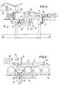
- each of the three printing stations A, B, C two printing devices 46, 48 are arranged, of which the device 46 serves for printing on the conical neck section 12 and the device 48 for printing on the cylindrical section 16.
- Each of the two printing devices 46 and 48 is provided with a screen printing stencil 50 and 52 as well as squeegees 34 and 36 cooperating therewith. Since the printing device 48 serves to print on the cylindrical section 16 of the bottle 10, it does not require any further explanation, since this is a known and customary device.
- the screen printing stencil 52 is displaced with respect to the bottle 10 rotating about its longitudinal axis, but otherwise stationary, transversely to its longitudinal axis, as is customary and known when printing cylindrical articles.
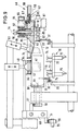
- FIG. 9 of the drawing shows the relative position of the bottle 10 with the conical neck section 12 and the printing device 46 with the area 51 of the screen printing stencil 50.
- each bottle 10 is to be provided both on the conical neck section 12 and on the cylindrical section 16 with a plurality of partial printed images 40, 42 which complement one another to form an overall printed image, it must be ensured that the Bottle 10 in each printing station A, B, C is aligned in the circumferential direction in a certain manner in relation to the respective screen printing stencils 50 and 52 and thus to the print image attached therein.
- the print image does not extend over the entire circumference of 360 ° of the article, it is frequently to be applied to a specific circumferential area thereof, for example to indicate the presence of seams or other markings which are present on the outside of the bottle and Z. B. may have arisen in their manufacture to take into account.
- a registration step is therefore provided in the transport direction 18 in front of each of the printing stations A, B, C, in which the bottle is aligned.
- the distance by which the transport element 70 can be moved in the transport direction 18 and in the opposite direction corresponds to the distance between the registration station 38 and the associated printing station.
- the transport device 70 serves to transport the bottle 10, after it has been aligned in the circumferential direction in the registration station 38, while maintaining this aligned position in the associated printing station.
- the two holding parts 76, 78 are at a distance from one another which allows the bottle to be brought into the position described between the two parts. As soon as this position has been reached, the distance between the two holder parts 76, 78 is reduced by an axial displacement thereof, the bottle 10 being gripped by both holder parts in the usual way, ie that Holding part 76 engages around the bottom region of the bottle 10 and the holding part 78 engages in the opening 14 of the bottle.
- the transport element 70 takes over the function of holding the bottle in its now defined circumferential position.
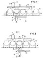
- the transport element 70 which is at this time in the registration station, but in its lower position shown in FIG. 8 of the drawing, is moved upward from this into the position according to FIG. 6, in which the two receiving elements 73 and the suction cups 74 rest against the bottle, the latter preventing the bottle from twisting due to the negative pressure which then becomes effective and securing the bottle in its aligned position.
- the transport device 70 is then moved downwards in order to release the bottle, wherein the negative pressure can be switched off, so that the bottle can be freely rotated in the course of the following printing process.
- This position of the parts is shown in Figures 8 and 9.
- the transport device 70 can then be moved back against the transport direction 18 back into the registration station in order to place the next bottle in the one already described Record manner that had been transported from the pair of chains 20, 22 in the registering station in the previous transport step.
- the bottle is released from the two holding parts 80, 82 by moving them apart. Since the pair of chains 20, 22 with the receiving elements 30, 32 had also been advanced by one transport step in the direction of the arrow 18 during the transport step of the transport element 70, the two receiving elements 30, 32 from which the bottle 10 passes through in the registering station are now located the transport device 70 had been raised in the printing station, so that when the printed bottle is released by the holder 80, 82 the bottle falls back down into these two receiving elements 30, 32 of the chains 20, 22. This presents no problems since, as already mentioned, the distance between the bottle in its raised position and the position that the bottle occupies when it is carried by both receiving elements 30, 32 of the chains 20, 22 is only small.
- a toothed segment 66 is furthermore arranged coaxially to the axis of rotation 54, with which a toothed rack 67 which can be reciprocated in the horizontal plane meshes, so that a back and forth movement of the rack 67 has corresponding pivoting movements of the screen printing stencil 50 about the vertical axis 54.
- the squeegee 34 is moved back in the direction of arrow 93 until the stencil can return to its normal shape, in which it is so far from the apex region of the neck section 12, that at the latest before the start of the pivoting movement in the opposite direction back to the starting position There is no fear of contact between template 50 and the following bottle to be moved into the printing station.
- the screen printing stencil device 46 used for printing the conical neck section 12 is arranged in a horizontal plane, in which the reciprocating pivoting movements about the axis of rotation 54 are also carried out. This means that the screen printing stencil does not project into the transport path of the bottles transported through the station in any conceivable position of the parts.
- the additional transport element 70 can also be provided with a gripper or another device which allows the bottle to be transported from the respective registration station to the downstream printing station without the bottle being given in the registration station Orientation with respect to their circumferential position undergoes a change.
Abstract
Description
Die Erfindung betrifft ein Verfahren und eine Vorrichtung zum Bedrucken von wenigstens teilweise konisch ausgebildeten Artikeln unter Anwendung des Siebdruckverfahrens gemäß dem Oberbegriff des Anspruches 1 bzw. des Anspruches 5.The invention relates to a method and a device for printing at least partially conical articles using the screen printing method according to the preamble of
Das Bedrucken von konisch geformten Artikeln oder solchen Artikeln, die konische Abschnitte aufweisen, ist insbesondere im Zusammenhang mit dem Bedrucken von Behältern, z. B. Flaschen, die als Verpackungen dienen, bekannt. Bei Flaschen und ähnlichen Artikeln ist in vielen Fällen der Übergang zwischen dem eigentlichen Flaschenkörper und dem Ende der Flasche, welches die Öffnung trägt, häufig konisch ausgebildet. In Anbetracht der Vielzahl von heute üblichen Formen gerade auf dem Verpackungssektor werden aber auch solche Behälter verwendet, die über den größten Teil ihrer axialen Erstreckung, ggf. sogar über ihre gesamte Länge, im wesentlichen konisch ausgebildet sind. Jedenfalls bei Anwendung des Siebdrucks erfolgt das Bedrucken von gekrümmten Flächen im allgemeinen in der Weise, daß sie an der Siebdruckschablone abgewickelt werden, wobei zur Erzielung eines guten Druckbildes die Geschwindigkeit, mit der die zu bedruckenden Fläche während des Druckvorgangs beweht wird, der Geschwindigkeit, mit welcher die Siebdruckschablone dabei bewegt wird, entspricht. Der Querschnitt des Artikels braucht dabei in dem Bereich, in welchem das Druckbild aufzubringen ist, nicht unbedingt einen rotationssymmetrischen Querschnitt aufzuweisen. Es reicht aus, daß jener Bereich der Umfangsfläche, der mit dem Druckbild zu versehen ist, während des Druckvorganges an der Siebdruckschablone abgewickelt werden kann.The printing of conically shaped articles or those articles which have conical sections is particularly in connection with the printing of containers, e.g. B. bottles that serve as packaging are known. In the case of bottles and similar articles, in many cases the transition between the actual bottle body and the end of the bottle which carries the opening is often conical. In view of the large number of shapes common today, particularly in the packaging sector, containers are also used which are essentially conical over most of their axial extension, possibly even over their entire length. In any case, when using screen printing, the printing of curved surfaces is generally carried out in such a way that they are carried out on the screen printing stencil, the speed at which the surface to be printed on is moved during the printing process, the speed, to achieve a good printing image which the screen printing template is moved corresponds to. The cross section of the article need not necessarily have a rotationally symmetrical cross section in the area in which the printed image is to be applied. It is sufficient for that area of the peripheral surface to be provided with the printed image to be unwound on the screen printing stencil during the printing process can.
Die konische Ausgestaltung des Artikels oder eines Abschnittes desselben, der mit dem Aufdruck zu versehen ist, weist drucktechnisch insofern eine Besonderheit auf, als die einzelnen Bereiche unterschiedlichen Durchmessers des konischen Abschnittes unterschiedliche Umfangsgeschwindigkeiten aufweisen derart, daß bei gegebener Winkelgeschwindigkeit die Umfangsgeschwindigkeit mit zunehmendem Durchmesser zunimmt. Dies muß in bekannter Weise beim Abwickeln des Artikels an der Siebdruckschablone während des Druckvorganges berücksichtigt werden mit dem Ergebnis, daß der das Druckbild tragende Abschnitt der Siebdruckschablone während des Druckvorganges eine Bewegung entlang einem Kreisbogen ausführt, dessen Radius mit zunehmendem Konuswinkel, also dem Winkel zwischen der Längsachse des zu bedruckenden Objektes und der zu bedruckenden Fläche, abnimmt.The conical configuration of the article or of a section thereof, which is to be provided with the imprint, has a peculiarity in terms of printing technology in that the individual areas of different diameters of the conical section have different peripheral speeds in such a way that, for a given angular velocity, the peripheral speed increases with increasing diameter. This must be taken into account in a known manner when the article is unwound on the screen printing stencil during the printing process, with the result that the section of the screen printing stencil carrying the printed image executes a movement along a circular arc during the printing process, the radius of which increases with increasing cone angle, i.e. the angle between the Longitudinal axis of the object to be printed and the area to be printed decreases.
Eine weitere Besonderheit des Bedruckens von konischen Artikeln ergibt sich daraus, daß der im Verlauf des Druckvorganges jeweils mit dem Aufdruck zu versehene Abschnitt der Konusfläche, der der Rakel gegenüberliegt, bei horizontaler Anordnung des Objektes während des Druckvorganges unter einem spitzen Winkel zur Horizontalen verläuft. Entsprechendes gilt beim Bedrucken des Artikels, wenn dessen Längsachse dabei vertikal verläuft. Da während des Bedruckungsvorganges die jeweils zusammenwirkenden Bereiche von Siebdruckschablone und Artikel jedenfalls unter der Einwirkung der Rakel zueinander parallel, normalerweise in einem sehr geringen Abstand voneinander, ggf. aber auch in Kontakt miteinander, verlaufen, muß bei horizontaler oder vertikaler Anordnung des Artikels während des Bedruckungsvorganges die Siebdruckschablone entsprechend dem schrägen Verlauf der zu bedruckenden Konusfläche jedenfalls dann ebenfalls schräg angeordnet sein, wenn ein qualitativ hochwertiges Druckbild erzeugt werden soll. Diese hat bei bekannten Verfahren und Vorrichtungen gewisse Schwierigkeiten zur Folge, und zwar insbesondere dann, wenn die zu bedruckenden Objekte in dichter Folge, also in geringen Abständen voneinander, durch die Siebdruckmaschine transportiert werden. Es ist bei modernen Maschinen zur Erzielung einer ausreichenden Produktivität üblich, die Artikel automatisch durch die Druckmaschine hindurchzutransportieren, und zwar insbesondere dann, wenn nacheinander mehrere Druckbilder zur Erzielung eines Gesamt-Druckbildes auf dem Artikel aufzubringen sind. Theoretisch besteht zwar die Möglichkeit, die durch den schrägen Verlauf der zu bedruckenden Fläche verursachten Schwierigkeiten dadurch zu vermeiden, daß das Objekt beim Druckvorgang so positioniert wird, daß der jeweils in Kontakt mit der Siebdruckschablone befindliche Bereich der zu bedruckenden Fläche z. B. horizontal verläuft. Dies ermöglicht auch eine im wesentlichen horizontale Anordnung der Siebdruckschablone. Allerdings hat eine schräge Positionierung des zu bedruckenden Artikels in der Druckstation immer eine Komplizierung der Handhabung des Artikels in der Druckmaschine zur Folge, die entweder zu Einbußen bei der Produktivität führt oder aber sehr komplizierte Einrichtungen erfordert, die die Vorrichtung störanfällig machen. Es ist deshalb im allgemeinen vorzuziehen, daß der Artikel beim Bedrucken eine Position einnimmt, bei welcher seine Längsachse im wesentlichen horizontal verläuft, zumal häufig gleichzeitig mit dem Bedrucken der konischen Fläche auch zylindrische odere andere Flächen bedruckt werden, bei denen ebenfalls die Verwendung einer in horizontaler Ebene bewegbaren Schablone bevorzugt wird. Dies hat bei bekannten Vorrichtungen zur Folge, daß eine schwenkbare Siebdruckschablone entsprechend dem Verlauf der zu bedruckenden Fläche schräg angeordnet sein muß, also gegenüber der Horizontalen unter einem Winkel verläuft, welcher übereinstimmt mit dem Konuswinkel. Diese Anordnung erfordert jedoch einen gewissen Platzbedarf in der Druckstation zu beiden Seiten des Artikels, da die Bewegungsbahn der Siebdruckschablone sich zu beiden Seiten des zu bedruckenden Artikels aufgrund der Tatsache, daß die Achse, um welche die Schwenkbewegung der Schablone erfolgt, entsprechend dem Konuswinkel schräg verläuft, in die zu beiden Seiten des Artikels neben demselben befindlichen Bereiche bewegt wird mit der Folge, daß diese Bereiche beim Druckvorgang freigehalten werden müssen. Dies schließt die Möglichkeit aus, die zu bedruckenden Artikel in dichter Folge, ggf. nur in einem Abstand von einigen Millimetern voneinander, durch die Siebdruckvorrichtung und die Druckstationen zu führen.Another peculiarity of the printing of conical articles results from the fact that the portion of the cone surface to be provided with the imprint in the course of the printing process, which is opposite the doctor blade, runs at an acute angle to the horizontal during the printing process when the object is arranged horizontally. The same applies to printing on the article if the longitudinal axis is vertical. Since during the printing process the interacting areas of screen printing stencil and article run parallel to each other under the influence of the squeegee, normally at a very small distance from one another, but possibly also in contact with one another, the article must be arranged horizontally or vertically during the printing process the screen printing stencil must also be arranged obliquely in accordance with the oblique course of the conical surface to be printed if a high-quality print image is to be generated. This has certain difficulties with known methods and devices the result, in particular when the objects to be printed are transported in close succession, that is to say at short distances from one another, through the screen printing machine. It is customary in modern machines to achieve sufficient productivity to automatically transport the articles through the printing press, in particular when several print images are to be applied to the article in order to obtain an overall print image. Theoretically, there is the possibility of avoiding the difficulties caused by the oblique course of the surface to be printed in that the object is positioned during the printing process in such a way that the area of the surface to be printed on which is in contact with the screen printing stencil, for. B. runs horizontally. This also enables a substantially horizontal arrangement of the screen printing stencil. However, an inclined positioning of the article to be printed in the printing station always results in a complication of the handling of the article in the printing machine, which either leads to a loss of productivity or requires very complicated devices that make the device susceptible to failure. It is therefore generally preferable for the article to assume a position in printing in which its longitudinal axis is essentially horizontal, especially since cylindrical or other surfaces are also printed simultaneously with the printing on the conical surface, which also use a horizontal one Level movable stencil is preferred. In known devices, this has the consequence that a pivotable screen printing stencil must be arranged obliquely in accordance with the course of the surface to be printed, that is to say runs at an angle with respect to the horizontal which corresponds to the cone angle. However, this arrangement requires a certain amount of space in the printing station on both sides of the article, since the path of movement of the screen printing stencil is on both sides of the article to be printed due to the fact that the axis around which the pivoting movement of the stencil takes place, according to the cone angle runs obliquely, into the areas located on both sides of the article next to the same, with the result that these areas must be kept clear during the printing process. This precludes the possibility of passing the articles to be printed in close succession, possibly only at a distance of a few millimeters from one another, through the screen printing device and the printing stations.
Der Erfindung liegt die Aufgabe zugrunde, Verfahren und Vorrichtung der einleitend beschriebenen Art so zu verbessern, daß die Erzielung einer hohen Produktivität möglich ist. Es soll ferner möglich sein, die Siebdruckschablone während des Druckvorganges in einer Ebene zu verschwenken, die parallel zur Längsachse des zu bedruckenden Artikels verläuft. Bei während des Bedruckungsvorganges horizontal angeordneten Artikeln soll - unabhängig vom Winkel, den die zu bedruckende Fläche mit der Längsachse des Artikels einschließt - die Achse, um welche die Siebdruckschablone während des Bedruckens verschwenkt wird, vertikal verlaufen können, so daß die Siebdruckschablone unabhängig von ihrer während des Bedruckens des Artikels eingenommenen Winkelposition eine bestimmte Höhenlage nicht unterschreitet, die oberhalb des Bewegungsbereiches der Artikel liegt.The invention has for its object to improve the method and apparatus of the type described in the introduction so that the achievement of high productivity is possible. It should also be possible to pivot the screen printing stencil during the printing process in a plane that runs parallel to the longitudinal axis of the article to be printed. In the case of articles arranged horizontally during the printing process, regardless of the angle that the surface to be printed forms with the longitudinal axis of the article, the axis about which the screen printing stencil is pivoted during printing should be able to run vertically, so that the screen printing stencil is independent of it during the printing position of the article does not fall below a certain height, which is above the range of movement of the article.
Diese Aufgabe wird mit den Mitteln, die im Kennzeichen des Anspruches 1 bzw. des Anspruches 6 angeführt sind, gelöst. Weitere Ausgestaltungen ergeben sich aus den Unteransprüchen.This object is achieved with the means specified in the characterizing part of
Zwar sind aus der DE-A-29 40 113 ein Verfahren zum Bedrucken eines Artikels und eine Siebdruckvorrichtung zur Durchführung dieses Verfahrens bekannt, bei welchen die Verwendung einer Siebdruckschablone vorgesehen ist, die während des Druckvorganges auf einer Bahn umläuft, die der Mantelfläche eines Kegelstumpfes entspricht. Dabei geht es jedoch um das Bedrucken von langgestreckten Objekten, die an der um eine vertikale Achse umlaufenden Siebdruckschablone etwa tangential vorbeigeführt werden. Das der Erfindung zugrunde liegende Problem, das Bedrucken von Artikeln zu verbessern, die konisch ausgebildet sind, geht aus der Vorveröffentlichung nicht hervor. Dies gilt auch für die Mittel, die die Erfindung zur Lösung dieses Problems vorschlägt, abgesehen von der bereits erwähnten Verwendung einer Siebdruckschablone, die während des Druckvorganges um eine vertikale Achse auf einer Bahn umläuft, die der Mantelfläche eines Kegelstumpfes entspricht.DE-A-29 40 113 discloses a method for printing an article and a screen printing device for carrying out this method, in which the use of a screen printing stencil is provided which rotates during the printing process on a path which corresponds to the lateral surface of a truncated cone . However, it is about the printing of elongated objects, the vertical one The screen printing stencil running around the axis should be passed approximately tangentially. The problem underlying the invention of improving the printing of articles which are conical is not apparent from the prior publication. This also applies to the means which the invention proposes to solve this problem, apart from the use of a screen printing stencil mentioned above, which rotates during the printing process about a vertical axis on a path which corresponds to the lateral surface of a truncated cone.
Wenn vorstehend und in der nachfolgenden Beschreibung eines Ausführungsbeispiels überwiegend von Flaschen gesprochen wird, soll dies keine Beschränkung der Anwendung der Erfindung bedeuten. Diese ist überall dort mit Nutzen verwendbar, wo es um das Bedrucken von an der Siebdruckschablone abwälzbaren Flächen geht, deren Krümmungsradius in Richtung des Rakelverlaufs eine mehr oder weniger gleichmäßige Änderung erfährt. Dabei ist es nicht erforderlich, daß die so ausgebildete Fläche sich über 360° erstreckt.If above and in the following description of an exemplary embodiment one speaks predominantly of bottles, this should not mean any restriction of the application of the invention. This can be used wherever it is a question of printing on surfaces that can be rolled off on the screen printing stencil, the radius of curvature of which changes more or less uniformly in the direction of the doctor blade path. It is not necessary that the surface so formed extends over 360 °.
Im allgemeinen wird die Siebdruckschablone hin- und hergehende Schwenkbewegungen durchführen, wobei in einer Bewegungsrichtung das Bedrucken erfolgt. Es ist aber auch möglich, die Siebdruckschablone nur in einer Richtung, ggf. absatzweise, rotieren zu lassen.In general, the screen printing stencil will perform reciprocating swiveling movements, with the printing taking place in one direction of movement. However, it is also possible to rotate the screen printing stencil only in one direction, if necessary in sections.
In der Zeichnung ist ein Ausführungsbeispiel der Erfindung dargestellt. Es zeigen:
- Fig. 1
- im Schema die Vorderansicht einer Siebdruckmaschine,
- Fig. 2
- die dazugehörige Draufsicht,
- Fig. 3
- die Draufsicht auf die im Bereich einer Druckstation befindlichen Flaschen, wobei jedoch zur Erzielung einer besseren Übersicht Siebdruckschablonen und zugehörige Teile weggelassen sind,
- Fig. 4
- eine der Fig. 3 entsprechende Darstellung, jedoch mit den beiden zu jeder Druckstation gehörenden Siebdruckschablonen,
- Fig. 5
- ein Schnitt nach der Linie V-V der Fig. 3,
- Fig. 6
- eine Ansicht in Richtung des Pfeiles VI der Fig. 5, mit der zusätzlichen Transporteinrichtung in der Ausgangsposition am Beginn eines Transportschrittes,
- Fig. 7
- eine der Fig. 6 entsprechende Darstellung mit der zusätzlichen Transporteinrichtung in einer Zwischenposition,
- Fig. 8
- eine der Fig. 6 entsprechende Darstellung mit der zusätzlichen Transporteinrichtung in der Endposition,
- Fig. 9
- einen Schnitt nach der Linie IX-IX der Fig. 8,
- Fig. 10
- die Draufsicht auf den Rahmen der Siebdruckschablone mit daran angebrachter und gespannter Schablone.
- Fig. 1
- in the diagram the front view of a screen printing machine,
- Fig. 2
- the corresponding top view,
- Fig. 3
- the top view of the bottles located in the area of a printing station, with screen printing stencils and associated parts being omitted for a better overview,
- Fig. 4
- a representation corresponding to FIG. 3, however with the two screen printing stencils belonging to each printing station,
- Fig. 5
- a section along the line VV of Fig. 3,
- Fig. 6
- 5, with the additional transport device in the starting position at the beginning of a transport step,
- Fig. 7
- 6 shows a representation corresponding to FIG. 6 with the additional transport device in an intermediate position,
- Fig. 8
- 6 shows a representation corresponding to FIG. 6 with the additional transport device in the end position,
- Fig. 9
- 7 shows a section along the line IX-IX of FIG. 8,
- Fig. 10
- the top view of the frame of the screen printing template with attached and tensioned template.
Die in den Fig. 1 und 2 dargestellte Siebdruckmaschine ist mit drei Druckstationen A, B und C versehen, in denen jeweils zwei Siebdruckschablonen zum Aufbringen von zwei Teil-Druckbildern vorgesehen sind, wobei sich jeweils drei zusammengehörende Teil-Druckbilder auf dem bedruckten Artikel zu einem Gesamt-Druckbild ergänzen. Bei den zu bedruckenden Artikeln handelt es sich um Flaschen 10, deren Halsabschnitt 12 in Richtung auf die Öffnung 14 im wesentlichen konisch sich verjüngend ausgebildet ist. Fig. 9 zeigt, daß die Mantelfläche des Halsabschnittes 12 im Längsschnitt nicht genau linear verlaufend ausgebildet zu sein braucht. Sie kann vielmehr geringfügig nach außen gewölbt, also konvex, gegebenenfalls auch geringfügig konkav. ausgebildet sein. Dies ist jedoch nicht nachteilig, weil die Siebdruckschablone an derartig geringe Abweichungen vom geraden Verlauf unter der Einwirkung der Rakel sich ohne weiteres anpassen kann. Der Körper der Flasche 10 setzt sich an dem der Öffnung 14 abgekehrten Ende des Halsabschnittes 12 in einem im wesentlichen zylindrischen Abschnitt 16 fort. Sowohl der konische Halsabschnitt 12 als auch der zylindrische Abschnitt 16 sind mit jeweils einem Gesamt-Druckbild zu versehen, das jeweils in drei Druckvorgängen aufzubringen ist.The screen printing machine shown in FIGS. 1 and 2 is provided with three printing stations A, B and C, in each of which two screen printing stencils are provided for the application of two partial printing images, with three partial printing images belonging together on the printed article to form one Complete the overall print image. The articles to be printed are
Die zu bedruckenden Flaschen 10 werden in Richtung des Pfeiles 18 schrittweise durch die Siebdruckmaschine und deren Behandlungsstationen transportiert. Dazu ist letztere mit einem ersten Transportmittel in Form eines Kettenpaares versehen, dessen beide Ketten 20, 22 jeweils in einer vertikalen Ebene umlaufen. An den beiden Enden der Siebdruckmaschine sind Umlenkräder 23, 24 vorgesehen, von denen wenigstens ein Paar auch zum Antrieb der beiden Ketten 20, 22 dient.The
Die zu bedruckenden Flaschen 10 werden über eine der Siebdruckmaschine vorgeschaltete Aufgabeeinrichtung 26 zugeführt und in der Aufgabestation 28 dem Kettenpaar 20, 22 aufgegeben. Jede Kette 20, 22 ist dazu mit Aufnahmeelementen 30, 32 versehen, deren Ausnehmungen 31, 33 (Fig. 5, 6, 9) an die Querschnittsform des jeweils aufzunehmenden Abschnittes der Flasche 10 angepaßt sind. Die Aufnahmeelemente 30, 32 sind so angeordnet, daß jeweils zwei einander gegenüberliegende Aufnahmeelemente 30, 32 gemeinsam eine Flasche 10 tragen. Die in den Fig. 1 und 2 nicht dargestellten Aufnahmeelemente sind in Bewegungsrichtung des Kettenpaares 20, 22 in so kurzen Abständen angebracht, daß zwischen zwei von dem Kettenpaar getragenen benachbarten Flaschen ein Abstand von ggf. nur einigen Millimetern vorhanden ist.The
In Transportrichtung 18 hinter jeder der Druckstationen A, B, C ist eine Trockenstation D, E, F angeordnet, die von den Flaschen 10 durchlaufen wird, nachdem sie jeweils mit zwei getrennten Teil-Druckbildern 40, 42 (Fig. 5) versehen worden sind.Arranged in the
Die vorbeschriebenen Anordnungen und Ausgestaltungen sind allgemein bekannt, so daß sie keiner näheren Erläuterung bedürfen. Es ist auch möglich, in Abhängigkeit von den jeweiligen Gegebenheiten andere Ausgestaltungen und Anordnungen zu wählen. So ist es beispielsweise in Abhängigkeit von der Beschaffenheit der zu bedruckenden Artikel, von der Wahl der Druckfarben und ggf. weiteren Einflüssen möglich, auf das Vorhandensein von Trocknungsstationen zu verzichten. Andererseits können zusätzliche Behandlungsstationen vorgesehen sein, beispielsweise zum Beflammen oder Entstatisieren der Artikel.The arrangements and configurations described above are generally known, so that they require no further explanation. It is also possible depending on the particular Choosing other configurations and arrangements. For example, depending on the nature of the articles to be printed, the choice of printing inks and any other influences, it is possible to dispense with the presence of drying stations. On the other hand, additional treatment stations can be provided, for example for flaming or destatising the articles.
In jeder der drei Druckstationen A, B, C sind Zwei Druckeinrichtungen 46, 48 angeordnet, von denen die Einrichtung 46 zum Bedrucken des konischen Halsabschnittes 12 und die Einrichtung 48 zum Bedrucken des zylindrischen Abschnittes 16 dient. Jede der beiden Druckeinrichtungen 46 bzw. 48 ist mit einer Siebdruckschablone 50 bzw. 52 sowie damit zusammenwirkender Rakel 34 bzw. 36 versehen. Da die Druckeinrichtung 48 dazu dient, den zylindrischen Abschnitt 16 der Flasche 10 zu bedrucken, bedarf sie keiner näheren Erläuterung, da es sich hierbei um eine bekannte und übliche Einrichtung handelt. Während des Druckvorganges wird die Siebdruckschablone 52 gegenüber der um ihre Längsachse rotierenden, jedoch im übrigen stationären Flasche 10 quer zu deren Längsachse verschoben, wie dies beim Bedrucken zylindrischer Artikel üblich und bekannt ist.In each of the three printing stations A, B, C, two
Die Flasche 10 ist während des Bedruckungsvorganges - wie beim Vortransport in Richtung des Pfeiles 18 - liegend angeordnet, so daß ihre Längsachse horizontal verläuft. Demzufolge verläuft die Mantelfläche des konischen Abschnittes 12 im Längsschnitt, wie dies z. B. Fig. 9 zeigt, unter einem spitzen Winkel zur Längsachse 44 der Flasche 10. Da zumindest jener Bereich der Siebdruckschablone 50 der Einrichtung 46, der das Druckbild trägt und während des Bedruckens der Mantelfläche des Abschnittes 12 im wesentlichen parallel zu diesem verlaufen muß, bildet der das Druckbild 53 tragende Bereich 51 der Siebdruckschablone 50 die Mantelfläche eines Kegelstumpfes, dessen Konuswinkel bei vertikaler Längsachse 54 der Druckeinrichtung 46, die auch zugleich die Rotationsachse für die Einrichtung bildet, dem Konuswinkel des Halsabschnittes 12 entspricht. Insbesondere Fig. 9 der Zeichnung läßt die relative Lage der Flasche 10 mit dem konischen Halsabschnitt 12 und der Druckeinrichtung 46 mit dem Bereich 51 der Siebdruckschablone 50 erkennen.The
Da bei dem in der Zeichnung dargestellten Ausführungsbeispiel jede Flasche 10 sowohl am konischen Halsabschnitt 12 als auch am zylindrischen Abschnitt 16 jeweils mit mehreren Teil-Druckbildern 40, 42 zu versehen ist, die sich zu einem Gesamt-Druckbild ergänzen, muß gewährleistet sein, daß die Flasche 10 in jeder Druckstation A, B, C in Umfangsrichtung in bestimmter Weise zu den jeweiligen Siebdruckschablonen 50 und 52 und damit zu dem darin jeweils angebrachten Druckbild ausgerichtet ist. Darüber hinaus ist insbesondere bei rotationssymmetrischen Artikeln häufig das Druckbild dann, wenn es sich nicht über den gesamten Umfang von 360° des Artikels erstreckt, auf einem bestimmten Umfangsbereich desselben anzubringen, beispielsweise um dem Vorhandensein von Nähten oder sonstigen Markierungen, die außenseitig auf der Flasche vorhanden und z. B. bei deren Herstellung entstanden sein können, Rechnung zu tragen. Zum Zwecke der Ausrichtung der Flasche in Umfangsrichtung ist deshalb in Transportrichtung 18 jeweils einen Transportschritt vor jeder der Druckstationen A, B, C eine Passerstation 38 vorgesehen, in welcher das Ausrichten der Flasche geschieht.Since in the embodiment shown in the drawing each
Ferner ist jeder Druckstation A, B, C eine zusätzliche Transporteinrichtung 70 zugeordnet, welche im wesentlichen aus einem Träger 72 besteht, der oberseitig mit zwei Aufnahmeelementen 73 und zwei Saugnäpfen 74 versehen ist, die in einer quer zur Transportrichtung 18 verlaufenden vertikalen Ebene jeweils in einem Abstand voneinander angebracht sind, der sich aus dem Abmessungen des zu bedruckenden Artikels ergibt. Die Aufnahmeelemente 73 entsprechen bezüglich ihrer Funktion und ihrer Ausgestaltung den Aufnahmeelementen 30 und 32 der Ketten 20, 22. Beide Saugnäpfe sind über Schläuche 75 mit einer nicht dargestellten Unterdruckquelle verbunden. Die Transporteinrichtung 70 ist durch in der Zeichnung nicht dargestellte Antriebsmittel in Transportrichtung 18 und entgegengesetzt dazu hin- und herbewegbar sowie auf- und abbewegbar. Die Wegstrecke, um welche das Transportelement 70 in Transportrichtung 18 und entgegengesetzt dazu bewegbar ist, entspricht dem Abstand zwischen Passerstation 38 und zugehöriger Druckstation. Die Transporteinrichtung 70 dient dazu, die Flasche 10, nachdem sie in der Passerstation 38 in Umfangsrichtung ausgerichtet worden ist, unter Beibehaltung dieser ausgerichteten Position in die zugehörige Druckstation zu transportieren.Furthermore, each printing station A, B, C is assigned an
Die von dem Kettenpaar 20, 22 schrittweise durch die Siebdruckmaschine transportierten Flaschen 10 gelangen vor jeder Druckstation A, B, C zunächst in die jeweilige Passerstation 38, wobei es in der üblichen Weise möglich ist, vor der in Transportrichtung 18 ersten Druckstation A bzw. vor der zugeordneten Passerstation - und nachfolgend ggf. auch zwischen den Druckstationen B, C - zusätzliche Behandlungen durchzuführen. Jeder Passerstation 38 ist eine Halterung zugeordnet, die bei dem in der Zeichnung dargestellten Ausführungsbeispiel aus zwei Teilen 76, 78 besteht. Am Ende des durch das Kettenpaar 20, 22 bewirkten Transportschrittes befindet sich die Flasche 10 in einer Position zwischen den beiden Halterungsteilen 76, 78, jedoch nicht genau koaxial zu diesen, sondern um eine geringe Distanz von z. B. 1 - 2 mm nach unten versetzt angeordnet. Während des Transports der Flasche 10 durch das Kettenpaar 20, 22 weisen die beiden Halterungsteile 76, 78 einen Abstand voneinander auf, der es erlaubt, die Flasche in die beschriebene Position zwischen beiden Teilen zu bringen. Sobald diese Position erreicht worden ist, wird der Abstand zwischen den beiden Halterungsteilen 76, 78 durch eine axiale Verschiebung derselben verringert, wobei die Flasche 10 von beiden Halterungsteilen in üblicher Weise erfaßt wird, d. h., daß das Halterungsteil 76 den Bodenbereich der Flasche 10 umgreift und das Halterungsteil 78 in die Öffnung 14 der Flasche eingreift. Dabei wird gleichzeitig durch die beiden Halterungsteile 76, 78 eine Ausrichtung zu diesen durch geringes Anheben der Flasche 10 bewirkt, so daß am Ende der von den beiden Halterungsteilen ausgeführten Schließbewegung die Flasche 10 koaxial zu den sie nunmehr tragenden Halterungsteilen 76, 78 ausgerichtet ist.The
Der Passerstation 38 ist ein Sensor 55 zugeordnet, der einen Antrieb 56 steuert. Letzterer treibt über einen Riemen 58 das dem Boden der Flasche 10 zugeordnete Halterungsteil 76 an, so daß die Flasche 10 unter Mitnahme des Halterungsteiles 78 um ihre Längsachse rotiert. Die Flasche 10 ist mit einer Markierung 60 versehen, die von dem optischen Sensor 55 während der Rotationsbewegung der Flasche 10 erfaßt wird, so daß die Umfangsposition der Flasche erkannt und die Flasche durch gesteuerte Drehung um ihre Längsachse in eine bestimmte, definierte Orientierung gebracht werden kann, die der Position entspricht, in welcher das Aufbringen der Druckbilder in der folgenden Druckstation beginnen soll. Bei der Markierung kann es sich auch um irgendeine ohnehin an der Flasche vorhandene Markierung, beispielsweise eine Formnaht oder dergleichen handeln. Die mit der Passerung zusammenhängenden Einrichtungen und Maßnahmen sind allgemein bekannt, so daß sie keiner näheren Erläuterung bedürfen.A
Sobald die Flasche 10 durch entsprechende Rotationsbewegung der beiden Halterungsteile 76 und 78 in die richtige Umfangslage gebracht worden ist, übernimmt das Transportelement 70 die Funktion, die Flasche zu halten, und zwar in ihrer nunmehr definierten Umfangsposition. Dazu wird das Transportelement 70, welches sich zu diesem Zeitpunkt in der Passerstation, jedoch in seiner in Fig. 8 der Zeichnung dargestellten unteren Position befindet, aus dieser nach oben in die Position gemäß Fig. 6 bewegt, in welcher die beiden Aufnahmeelemente 73 und die Saugnäpfe 74 an der Flasche anliegen, wobei letztere aufgrund des dann wirksam werdenden Unterdruckes eine Verdrehung der Flasche verhindern und diese in ihrer ausgerichteten Lage sichern. Nachdem die beiden Halterungsteile 76 und 78 auseinander bewegt worden sind und dadurch die Flasche freigegeben haben, wird die Transporteinrichtung 70 in Transportrichtung 18 um eine Distanz bewegt, die dem Abstand zwischen Passerstation und zugeordneter Druckstation entspricht, so daß am Ende dieses Transportschrittes die ausgerichtete Flasche 10 sich zwischen den beiden Halterungsteilen 80 bzw. 82 der der Druckstation zugeordneten Halterung befindet. Fig. 7 zeigt eine Zwischenposition im Verlauf des Transportschrittes von der Passerstation 38 in die nachgeordnete Druckstation. Die beiden Halterungsteile 80 und 82 entsprechen im wesentlichen den Halterungsteilen 76 und 78 der Passerstation. Während des durch die zusätzliche Transporteinrichtung 70 bewirkten Transportschrittes von der Passerstation in die Druckstation befindet die Flasche 10 sich normalerweise in der Höhenlage, die ihrer Höhenlage in den beiden Stationen entspricht, wenn sie von den Halterungen 76, 78 bzw. 80, 82 gehalten wird. Es ist natürlich auch möglich, im Bedarfsfall das Transportelement 70 mit der von ihr gehaltenen Flasche 10 in der Passerstation zunächst geringfügig abzusenken, bevor der Transportschritt in Richtung auf die Druckstation durchgeführt wird, und es in der Druckstation wieder etwas anzuheben. In der Druckstation wird dann die Flasche 10 durch eine Verringerung des Abstandes zwischen den beiden Halterungsteilen 80, 82 von diesen in der üblichen Weise aufgenommen, wie dies beispielsweise in Fig. 9 dargestellt ist. Danach wird die Transporteinrichtung 70 nach unten bewegt, um die Flasche freizugeben, wobei der Unterdruck abgeschaltetet werden kann, so daß die Flasche im Zuge des folgenden Bedruckungsvorganges frei rotiert werden kann. Diese Position der Teile ist in den Figuren 8 und 9 dargestellt. Die Transporteinrichtung 70 kann dann entgegen der Transportrichtung 18 wieder in die Passerstation zurückbewegt werden, um dort die nächste Flasche in der bereits beschriebenen Weise aufzunehmen, die bei dem vorangegangenen Transportschritt vom Kettenpaar 20, 22 in die Passerstation transportiert worden war.As soon as the
Das Ausmaß der von der Transporteinrichtung 70 auszuführenden vertikalen Bewegungen ist in jedem Fall sehr gering, da es lediglich darauf ankommt, die Flasche 10 soweit nach oben anzuheben, daß sie außer Kontakt mit der jeweiligen Halterung 30 bzw. 32 der Kette 20 bzw. 22 kommt, um so eine ungehinderte Rotation der Flasche 10 in Passerstation und Druckstation zu ermöglichen. Die Transporteinrichtung 70 kann, wie insbesondere Fig. 5 und 9 zeigen, zwischen den beiden Ketten 20 und 22 angeordnet sein, so daß es sich außerhalb des Bewegungsbereiches der beiden Ketten und der von diesen getragenen Halterungen 30, 32 und damit der Flaschen befindet.The extent of the vertical movements to be carried out by the
Nach Beendigung des Druckvorganges in der Druckstation wird die Flasche von den beiden Halterungsteilen 80, 82 freigegeben, indem diese auseinanderbewegt werden. Da das Kettenpaar 20, 22 mit den Aufnahmeelementen 30, 32 während des Transportschrittes des Transportelementes 70 ebenfalls um einen Transportschritt in Richtung des Pfeiles 18 vorbewegt worden war, befinden sich nunmehr die beiden Aufnahmeelemente 30, 32, aus welchen die Flasche 10 in der Passerstation durch die Transporteinrichtung 70 angehoben worden war, in der Druckstation, so daß bei Freigabe der bedruckten Flasche durch die Halterung 80, 82 die Flasche nach unten in diese beiden Aufnahmeelemente 30, 32 der Ketten 20, 22 zurückfällt. Dies bereitet keinerlei Probleme, da, wie bereits gesagt, der Abstand zwischen der Flasche in ihrer angehobenen Position und der Position, die die Flasche einnimmt, wenn sie von beiden Aufnahmelementen 30, 32 der Ketten 20, 22 getragen wird, nur gering ist.After the printing process in the printing station has ended, the bottle is released from the two holding
Die Druckeinrichtung 46 ist mit einem kreisringförmigen Rahmen 84 versehen, an dem die kreisförmige Siebdruckschablone 50 angebracht ist. Die vorgespannte Siebdruckschablone weist dabei innerhalb des Rahmens zunächst einen ebenen Verlauf auf. Die Form eines an den Konus des Halsabschnittes 12 angepaßten Kegelstumpfes wird dadurch erreicht, daß innerhalb des Rahmens 84 koaxial zu diesem ein entsprechend bemessenes Einsatzteil 86 als Formstück angeordnet wird, welches in Richtung der vertikal zur Ebene des Rahmens 84 verlaufenden Achse gegen die Siebdruckschablone unter gleichzeitiger Beaufschlagung des zentralen Bereiches derselben vorsteht derart, daß die Siebdruckschablone die in Fig. 9 der Zeichnung dargestellte Form eines Kegelstumpfes annimmt, bei welcher der kreisringförmige Bereich zwischen Rahmen 84 und Formstück 86 der Siebdruckschablone die Kegelfläche bildet.The
Bei dem in der Zeichnung dargestellten Ausführungsbseispiel ist dazu der Schablonenrahmen 84 innenseitig mit einer einstückig angebrachten Halterung 88 versehen, welche in Draufsicht (Fig. 10) die Form etwa einer halben Kreisringscheibe hat, die im wesentlichen koaxial zur Achse des ringförmigen Rahmens 84 und damit auch in montiertem Zustand der Teile koaxial zur Schwenkachse 54 (Fig. 9) angeordnet ist. In diese Halterung 88 und dazu koaxial wird das Formstück 86 eingesetzt, welches lösbar über Laschen 85 und Schrauben 87 an der Halterung 88 in der Position fixiert wird, in welcher die Schablone 50 in die Form eines Kegelstumpfes mit dem gewünschten Kegelwinkel gespannt ist. Das Formstück 86 ist an seiner der Schablone 50 abgekehrten Seite mit einer koaxialen Ausnehmung 89 versehen, in die in montiertem Zustand der Gesamtanordnung ein entsprechend geformtes und dimensioniertes Paßstück 57 eingreift, welches mit einem koaxial zur Rotationsachse 54 verlaufenden rohrförmigen Fortsatz 90 versehen ist, der unter Zwischenschaltung von die Rotationsbewegung erlaubenden Lagern 92 von einer am Maschinenrahmen angebrachten Brücke 64 gehalten wird. An dem mit dem Formstück 86 verbundenen Paßstück 57 ist weiterhin ein Zahnsegment 66 koaxial zur Roationsachse 54 angebracht, mit welchem eine in horizontaler Ebene hin- und herbewegbare Zahnstange 67 kämmt, so daß eine Hin- und Herbewegung der Zahnstange 67 entsprechende Schwenkbewegungen der Siebdruckschablone 50 um die vertikale Achse 54 zur Folge hat.In the exemplary embodiment shown in the drawing, the
Die mit der Siebdruckschablone 50 zusammenwirkende Rakel 34 ist derart schräg angeordnet, daß ihre untere Begrenzungskante, die dem Scheitelbereich des Halsabschnittes 12, in welchem jeweils die Übertragung der Druckfarbe erfolgt, gegenüberliegt, im wesentlichen parallel zum Scheitelbereich verläuft. Die Rakel 34 ist lediglich in Richtung der Pfeile 93, 94 hin- und herbewegbar derart, daß sie während der das Aufbringen des Druckbildes bewirkenden Schwenkbewegung die Siebdruckschablone 50 in dem dem Scheitelbereich des Halsabschnittes 12 gegenüberliegenden Bereich elastisch in Richtung auf den Halsabschnitt 12 spannt, so daß dieser Bereich der Siebdruckschablone die für die Übertragung der Druckfarbe notwendige Position einnimmt. Spätestens vor Beginn der in umgekehrter Richtung erfolgenden Schwenkbewegung zurück in die Ausgangslage wird die Rakel 34 in Richtung des Pfeiles 93 soweit zurückbewegt, daß die Schablone wieder ihre normale Form annehmen kann, in welcher sie so weit vom Scheitelbereich des Halsabschnittes 12 entfernt ist, daß eine Berührung zwischen Schablone 50 und der folgenden in die Druckstation zu bewegenden Flasche nicht zu befürchten ist. Entsprechendes gilt für das Zusammenwirken von Siebdruckschablone 52 für das Aufbringen eines Druckbildes auf den zylindrischen Abschnitt der Flasche und der damit zusammenwirkenden Rakel 36. Auf diese Weise können zusätzliche Auf- und Abbewegungen der Siebdruckschablonen vermieden werden, welche Tatsache die Arbeitsgeschwindigkeit der Vorrichtung erhöht.The
Der senkrecht zur Bildebene der Fig. 9 hin- und herbewegbare Schlitten 68 für die Druckeinrichtung 48 ist mit einer Zahnstange 71 versehen, die mit einem über eine Welle 95 angetriebenen Ritzel 96 kämmt. Der Schlitten 68 trägt ferner eine Zahnstange 97, die mit einem Ritzel 98 kämmt, welches die Rotationsbewegung der Flasche 10 um ihre Längsachse während des Druckvorganges bewirkt. Der Antrieb für die Zahnstange 67, die die Druckeinrichtung 46 antreibt, wird von der Welle 95 oder einem damit in Verbindung stehenden Antriebsteil abgenommen, so daß die erforderliche Synchronität der Bewegungen aller beim Druckvorgang zusammenwirkenden Teile gewährleistet ist.The carriage 68 which can be moved back and forth perpendicularly to the image plane of FIG. 9 is provided with a
Bei der vorbeschriebenen Ausgestaltung und Anordnung der zusammenwirkenden Teile ist die für das Bedrucken des konischen Halsabschnittes 12 dienende Siebdruckschablonen-Einrichtung 46 in horizontaler Ebene angeordnete, in welcher auch die hin- und hergehenden Schwenkbewegungen um die Rotationsachse 54 ausgeführt werden. Dies bedeutet, daß die Siebdruckschablone in keiner denkbaren Position der Teile in die Transportbahn der durch die Station hindurchtransportierten Flaschen hineinragt.In the above-described configuration and arrangement of the interacting parts, the screen
Abweichend von dem in der Zeichnung dargestellten Ausführungsbeispiel kann das zusätzliche Transportelement 70 auch mit einem Greifer oder einer anderen Einrichtung versehen sein, die es erlaubt, die Flasche von der jeweiligen Passerstation in die nachgeordnete Druckstation zu transportieren, ohne daß die in der Passerstation der Flasche gegebene Orientierung bezüglich ihrer Umfangslage eine Änderung erfährt.In a departure from the exemplary embodiment shown in the drawing, the
Abweichend von dem in der Zeichnung dargestellten Ausführungsbeispiel braucht die konische Fläche, auf die der Aufdruck aufgebracht wird, nicht über einen Umfang von 360° verlaufen. Die Erfindung ist auch zum Aufbringen einer Dekoration auf solchen Flächen geeignet, die lediglich einen Teil-Konus begrenzen, dessen Kegelfläche sich z. B. nur über einen Umfangsbereich von 180° erstreckt.In contrast to the exemplary embodiment shown in the drawing, the conical surface to which the print is applied does not need to extend over a circumference of 360 °. The invention is also suitable for applying a decoration to such surfaces that only limit a partial cone, the conical surface of which, for. B. extends only over a circumferential range of 180 °.
Claims (14)
Applications Claiming Priority (2)
| Application Number | Priority Date | Filing Date | Title |
|---|---|---|---|
| DE4132668A DE4132668C2 (en) | 1991-10-01 | 1991-10-01 | Device and method for decorating a conical body |
| DE4132668 | 1991-10-01 |
Publications (2)
| Publication Number | Publication Date |
|---|---|
| EP0535512A1 true EP0535512A1 (en) | 1993-04-07 |
| EP0535512B1 EP0535512B1 (en) | 1995-08-09 |
Family
ID=6441900
Family Applications (1)
| Application Number | Title | Priority Date | Filing Date |
|---|---|---|---|
| EP92116214A Expired - Lifetime EP0535512B1 (en) | 1991-10-01 | 1992-09-23 | Method and apparatus for printing articles at least partially conical |
Country Status (4)
| Country | Link |
|---|---|
| US (1) | US5317967A (en) |
| EP (1) | EP0535512B1 (en) |
| JP (1) | JP3379018B2 (en) |
| DE (2) | DE4132668C2 (en) |
Cited By (11)
| Publication number | Priority date | Publication date | Assignee | Title |
|---|---|---|---|---|
| EP0707959A1 (en) * | 1994-10-11 | 1996-04-24 | Werner Kammann Maschinenfabrik GmbH. | Screen-printing process and device for carrying out said method |
| EP1029669A1 (en) * | 1999-02-19 | 2000-08-23 | Societe D'exploitation Des Machines Dubuit | Method of operating a printing machine comprising at least one object holding device rotatably mounted on a conveyor, and corresponding printing |
| FR2793189A1 (en) * | 1999-05-07 | 2000-11-10 | Schott Glas | SERIGRAPHY PRINTING DEVICE, IN PARTICULAR FOR PRINTING ON GLASS ARTICLES |
| DE10011058A1 (en) * | 2000-03-07 | 2001-09-20 | Isimat Gmbh Siebdruckmaschinen | Printing stencil for a screen printing machine and method for its production |
| US7378529B2 (en) | 1999-01-22 | 2008-05-27 | Wyeth | Heteroaryl, heterocyclic and aryl compounds which inhibit leukocyte adhesion mediated by VLA-4 |
| EP2363288A1 (en) * | 2010-03-03 | 2011-09-07 | KAMMANN Maschinenbau GmbH | Device and method for aligning objects |
| WO2012093077A1 (en) * | 2011-01-05 | 2012-07-12 | Till Gmbh | Machine for printing on containers |
| US9352594B1 (en) | 2015-06-30 | 2016-05-31 | Tapematic S.P.A. | Process and apparatus for digital printing on articles |
| CN106626733A (en) * | 2017-01-22 | 2017-05-10 | 广州市申发机电有限公司 | Full-automatic, rapid and efficient multi-color rotation hook face silk screen printing machine |
| CN109334234A (en) * | 2018-11-30 | 2019-02-15 | 福州清山压铸有限公司 | A kind of automatic rotation pad printer |
| CN110667234A (en) * | 2018-08-07 | 2020-01-10 | 广州柳川智能装备有限公司 | Taper control platform of screen printer |
Families Citing this family (25)
| Publication number | Priority date | Publication date | Assignee | Title |
|---|---|---|---|---|
| DE4431638A1 (en) * | 1994-09-06 | 1996-03-14 | Balsfulland Maschfabrik Gmbh | Process for the registration of rotatably received objects for the execution of printing processes |
| IL113552A (en) * | 1995-04-30 | 2005-09-25 | Hewlett Packard Indigo Bv | Apparatus and method for centerless printing of images particularly on cylindrical objects |
| PE34797A1 (en) * | 1995-06-01 | 1997-09-22 | Vidriera Monterrey S A De C V | METHOD AND MACHINE FOR DECORATING PACKAGING OR SIMILAR ITEMS |
| DE19607837A1 (en) * | 1996-03-01 | 1997-09-04 | Kammann Maschf Werner | Decorating objects or containers travelling along conveyor belt |
| US6283022B1 (en) | 1997-10-17 | 2001-09-04 | Deco Patents, Inc. | Apparatus and method for direct rotary screen printing radiation curable compositions onto cylindrical articles |
| DE19753588C2 (en) * | 1997-12-03 | 2000-01-20 | Dosoprint Gmbh | Can holding device for holding beverage cans for printing on the outer surface |
| US6079326A (en) * | 1998-05-15 | 2000-06-27 | Carl Strutz & Co., Inc. | Method and apparatus for using workpiece registration to inline decorate and cure workpieces |
| US6158339A (en) * | 1999-01-29 | 2000-12-12 | Alpha Metals, Inc. | Stencil holder assembly for use with solder paste stencil printers |
| US6684770B2 (en) | 2001-06-29 | 2004-02-03 | Deco Patents, Inc. | Apparatus and method for direct rotary printing compositions onto cylindrical articles |
| FR2892107B1 (en) * | 2005-10-13 | 2008-01-18 | Saverglass Soc Par Actions Sim | METHOD FOR AUTOMATICALLY AND SEQUENTIALLY LOADING OBJECTS AND CORRESPONDING EQUIPMENT. |
| DE102006001223A1 (en) * | 2006-01-10 | 2007-07-12 | Khs Ag | Apparatus for printing on bottles or similar containers |
| US7743702B2 (en) * | 2006-07-18 | 2010-06-29 | Max Levy Autograph, Inc. | Method for applying electronic circuits to curved surfaces |
| DE102009013477B4 (en) † | 2009-03-19 | 2012-01-12 | Khs Gmbh | Printing device for printing on bottles or similar containers |
| US9052176B1 (en) * | 2013-03-15 | 2015-06-09 | Joseph Stefano | Shell casing marker |
| FR3009520B1 (en) * | 2013-08-06 | 2015-09-04 | Dubuit Mach | ENHANCED INK JET PRINTING MACHINE |
| DE102015100338A1 (en) * | 2015-01-12 | 2016-07-14 | Khs Gmbh | Measuring device, measuring system and method for calibrating printing stations |
| US9908321B1 (en) * | 2016-04-28 | 2018-03-06 | Kalvani Ip Holdings, Llc | Systems and methods for identifying cartridge cases based on ink marking |
| CN107399154A (en) * | 2017-09-20 | 2017-11-28 | 太仓市黄发记机械模具制造有限公司 | A kind of difunctional printing machine |
| CN107934532A (en) * | 2017-12-27 | 2018-04-20 | 广州九红智能装备有限公司 | A kind of clamping conveying mechanism being used on full-automatic monochromatic screen printer |
| JP7181066B2 (en) * | 2018-11-29 | 2022-11-30 | 株式会社Screenホールディングス | WORK HOLDING DEVICE, PRINTING SYSTEM AND PRINTING METHOD |
| CN110254042B (en) * | 2019-04-30 | 2020-11-10 | 浙江申达化妆品包装有限公司 | Surface printing equipment for split charging bottle |
| CN111391480A (en) * | 2020-03-21 | 2020-07-10 | 台州市莱恩克智能科技有限公司 | Bottle lateral wall screen printing is with rotatory fixture |
| CN111572175B (en) * | 2020-06-03 | 2020-12-29 | 黑龙江天有为电子有限责任公司 | Silk screen printing mould and silk screen printing machine |
| JP2022038714A (en) * | 2020-08-27 | 2022-03-10 | 株式会社Screenホールディングス | Rotation position adjustment device and printing system |
| JP2022072404A (en) * | 2020-10-29 | 2022-05-17 | 株式会社Screenホールディングス | Printing device and printing method |
Citations (2)
| Publication number | Priority date | Publication date | Assignee | Title |
|---|---|---|---|---|
| GB454298A (en) * | 1935-03-25 | 1936-09-25 | Solar Lab | Improvements in and relating to methods of and apparatus for stenciling |
| US2116467A (en) * | 1935-08-22 | 1938-05-03 | Solar Lab | Machine for stenciling ware |
Family Cites Families (14)
| Publication number | Priority date | Publication date | Assignee | Title |
|---|---|---|---|---|
| US2111207A (en) * | 1933-12-30 | 1938-03-15 | Owens Illinois Glass Co | Apparatus for marking or decorating articles |
| US2127128A (en) * | 1937-05-10 | 1938-08-16 | Solar Lab | Stenciling apparatus |
| US2605700A (en) * | 1949-05-06 | 1952-08-05 | Solar Engineering & Equipment | Stencil decorating machine |
| US3146704A (en) * | 1962-09-26 | 1964-09-01 | Owens Illinois Glass Co | Decorating on bottles and the like |
| US3363546A (en) * | 1962-10-16 | 1968-01-16 | Owens Illinois Inc | Container decorating means with means for holding and indexing work |
| US3172357A (en) * | 1963-03-04 | 1965-03-09 | Strutz & Co Inc Carl | Pneumatically operated stenciling apparatus |
| US3388658A (en) * | 1964-02-04 | 1968-06-18 | Shenango Ceramics Inc | Method for decorating pottery |
| US3390756A (en) * | 1965-08-25 | 1968-07-02 | Monsanto Co | Geneva type actuating mechanism |
| US3398678A (en) * | 1967-01-03 | 1968-08-27 | Monsanto Co | Printing curved surfaces |
| US4338327A (en) * | 1978-10-06 | 1982-07-06 | Janssen Pharmaceutica, N.V. | Substituted 1-(2-aryl-1,3-dioxolan-2-ylmethyl)-1H-1,2,4-triazoles |
| DE2940113A1 (en) * | 1979-10-03 | 1981-06-25 | Werner Kammann Maschinenfabrik GmbH, 4980 Bünde | Item screen printing method - applies pattern two or more times in succession to oblong item without interruption |
| US4463671A (en) * | 1981-06-05 | 1984-08-07 | Rudolph Rome R | Silk-screen printing method and apparatus |
| MX156483A (en) * | 1983-12-15 | 1988-08-26 | Vitro Tec Fideicomiso | IMPROVEMENTS IN MACHINE FOR DECORATING TABLEWARE OR SIMILAR ITEMS |
| DE3804505A1 (en) * | 1988-02-13 | 1989-08-24 | Continental Ag | TIRED VEHICLE WHEEL |
-
1991
- 1991-10-01 DE DE4132668A patent/DE4132668C2/en not_active Expired - Fee Related
-
1992
- 1992-09-15 US US07/945,298 patent/US5317967A/en not_active Expired - Lifetime
- 1992-09-23 DE DE59203212T patent/DE59203212D1/en not_active Expired - Fee Related
- 1992-09-23 EP EP92116214A patent/EP0535512B1/en not_active Expired - Lifetime
- 1992-10-01 JP JP28949092A patent/JP3379018B2/en not_active Expired - Fee Related
Patent Citations (2)
| Publication number | Priority date | Publication date | Assignee | Title |
|---|---|---|---|---|
| GB454298A (en) * | 1935-03-25 | 1936-09-25 | Solar Lab | Improvements in and relating to methods of and apparatus for stenciling |
| US2116467A (en) * | 1935-08-22 | 1938-05-03 | Solar Lab | Machine for stenciling ware |
Cited By (16)
| Publication number | Priority date | Publication date | Assignee | Title |
|---|---|---|---|---|
| EP0707959A1 (en) * | 1994-10-11 | 1996-04-24 | Werner Kammann Maschinenfabrik GmbH. | Screen-printing process and device for carrying out said method |
| US7378529B2 (en) | 1999-01-22 | 2008-05-27 | Wyeth | Heteroaryl, heterocyclic and aryl compounds which inhibit leukocyte adhesion mediated by VLA-4 |
| US7741328B2 (en) | 1999-01-22 | 2010-06-22 | Elan Pharmaceuticals, Inc. | Heteroaryl, heterocyclic and aryl compounds which inhibit leukocyte adhesion mediated by VLA-4 |
| EP1029669A1 (en) * | 1999-02-19 | 2000-08-23 | Societe D'exploitation Des Machines Dubuit | Method of operating a printing machine comprising at least one object holding device rotatably mounted on a conveyor, and corresponding printing |
| FR2789933A1 (en) * | 1999-02-19 | 2000-08-25 | Dubuit Mach | PROCESS FOR IMPLEMENTING A PRINTING MACHINE COMPRISING AT LEAST ONE OBJECT HOLDER ROTATING MOUNTED ON A CONVEYOR, AND CORRESPONDING PRINTING MACHINE |
| US6230623B1 (en) | 1999-02-19 | 2001-05-15 | Societe d'Exploitation des Machines Debuit, a “Societe Anonyme” | Method of using a printing machine including at least one object support rotatably mounted on a conveyor, and corresponding printing machine |
| FR2793189A1 (en) * | 1999-05-07 | 2000-11-10 | Schott Glas | SERIGRAPHY PRINTING DEVICE, IN PARTICULAR FOR PRINTING ON GLASS ARTICLES |
| DE10011058A1 (en) * | 2000-03-07 | 2001-09-20 | Isimat Gmbh Siebdruckmaschinen | Printing stencil for a screen printing machine and method for its production |
| EP2363288A1 (en) * | 2010-03-03 | 2011-09-07 | KAMMANN Maschinenbau GmbH | Device and method for aligning objects |
| WO2012093077A1 (en) * | 2011-01-05 | 2012-07-12 | Till Gmbh | Machine for printing on containers |
| US9352594B1 (en) | 2015-06-30 | 2016-05-31 | Tapematic S.P.A. | Process and apparatus for digital printing on articles |
| EP3112175A1 (en) * | 2015-06-30 | 2017-01-04 | TAPEMATIC S.p.A. | Process and apparatus for digital printing on articles |
| CN106626733A (en) * | 2017-01-22 | 2017-05-10 | 广州市申发机电有限公司 | Full-automatic, rapid and efficient multi-color rotation hook face silk screen printing machine |
| CN110667234A (en) * | 2018-08-07 | 2020-01-10 | 广州柳川智能装备有限公司 | Taper control platform of screen printer |
| CN110667234B (en) * | 2018-08-07 | 2022-02-11 | 广州柳川智能装备有限公司 | Taper control platform of screen printer |
| CN109334234A (en) * | 2018-11-30 | 2019-02-15 | 福州清山压铸有限公司 | A kind of automatic rotation pad printer |
Also Published As
| Publication number | Publication date |
|---|---|
| DE4132668A1 (en) | 1993-04-08 |
| US5317967A (en) | 1994-06-07 |
| DE59203212D1 (en) | 1995-09-14 |
| JPH07214887A (en) | 1995-08-15 |
| EP0535512B1 (en) | 1995-08-09 |
| JP3379018B2 (en) | 2003-02-17 |
| DE4132668C2 (en) | 1993-09-30 |
Similar Documents
| Publication | Publication Date | Title |
|---|---|---|
| EP0535512B1 (en) | Method and apparatus for printing articles at least partially conical | |
| DE3936157C2 (en) | Method and device for printing objects | |
| EP0239038B1 (en) | Process and device for decorating objects by means of screen printing | |
| DE102014116405B4 (en) | Printing device and method for printing on containers | |
| EP1164010B1 (en) | Device for decorating articles | |
| EP1627816A1 (en) | Method for labelling containers and labelling machine for carrying out the method | |
| EP2363288A1 (en) | Device and method for aligning objects | |
| DE102013214185A1 (en) | Transport device for a container treatment machine | |
| DE2407986A1 (en) | METAL CONTAINER MOLDING METHOD AND EQUIPMENT | |
| EP3003879A1 (en) | Method for processing containers and container processing machine | |
| DE4436275C2 (en) | Method and device for printing individual objects | |
| DE102004016838A1 (en) | Method and device for aligning vessels for liquid or flowable media, in particular drinks | |
| EP0584542B1 (en) | Method and device for printing objects | |
| EP0441365B1 (en) | Method and device for applying labels to containers or similar objects | |
| DE2726289C3 (en) | Turning device arranged between two presses, especially for flat workpieces | |
| DE19728029A1 (en) | Method and device for decorating flat self-supporting objects | |
| DE2452050C2 (en) | Device for registering sheets in sheet-fed rotary printing machines | |
| DE2040599A1 (en) | Closing spindle for a machine for closing and opening bottles | |
| DE3220100C2 (en) | ||
| DE3925842C2 (en) | ||
| EP0575766A2 (en) | Method and apparatus for applying self-adhesive labels to containers | |
| EP4161861B1 (en) | Device for closing of containers | |
| DE2646943A1 (en) | LABELING STATION | |
| DE10131448A1 (en) | Method and device for applying label sleeves to objects | |
| DE2646942B2 (en) | Labeling station |
Legal Events
| Date | Code | Title | Description |
|---|---|---|---|
| PUAI | Public reference made under article 153(3) epc to a published international application that has entered the european phase |
Free format text: ORIGINAL CODE: 0009012 |
|
| AK | Designated contracting states |
Kind code of ref document: A1 Designated state(s): DE FR IT |
|
| 17P | Request for examination filed |
Effective date: 19930617 |
|
| 17Q | First examination report despatched |
Effective date: 19950130 |
|
| GRAA | (expected) grant |
Free format text: ORIGINAL CODE: 0009210 |
|
| AK | Designated contracting states |
Kind code of ref document: B1 Designated state(s): DE FR IT |
|
| PG25 | Lapsed in a contracting state [announced via postgrant information from national office to epo] |
Ref country code: IT Free format text: LAPSE BECAUSE OF FAILURE TO SUBMIT A TRANSLATION OF THE DESCRIPTION OR TO PAY THE FEE WITHIN THE PRE;WARNING: LAPSES OF ITALIAN PATENTS WITH EFFECTIVE DATE BEFORE 2007 MAY HAVE OCCURRED AT ANY TIME BEFORE 2007. THE CORRECT EFFECTIVE DATE MAY BE DIFFERENT FROM THE ONE RECORDED.SCRIBED TIME-LIMIT Effective date: 19950809 Ref country code: FR Free format text: THE PATENT HAS BEEN ANNULLED BY A DECISION OF A NATIONAL AUTHORITY Effective date: 19950809 |
|
| REF | Corresponds to: |
Ref document number: 59203212 Country of ref document: DE Date of ref document: 19950914 |
|
| EN | Fr: translation not filed | ||
| PLBE | No opposition filed within time limit |
Free format text: ORIGINAL CODE: 0009261 |
|
| STAA | Information on the status of an ep patent application or granted ep patent |
Free format text: STATUS: NO OPPOSITION FILED WITHIN TIME LIMIT |
|
| 26N | No opposition filed | ||
| PGFP | Annual fee paid to national office [announced via postgrant information from national office to epo] |
Ref country code: DE Payment date: 20080320 Year of fee payment: 16 |
|
| PG25 | Lapsed in a contracting state [announced via postgrant information from national office to epo] |
Ref country code: DE Free format text: LAPSE BECAUSE OF NON-PAYMENT OF DUE FEES Effective date: 20090401 |