EP0707859B1 - Récipient pour le stockage et l'administration de préparations d'injection, d'infusion et de diagnostic - Google Patents
Récipient pour le stockage et l'administration de préparations d'injection, d'infusion et de diagnostic Download PDFInfo
- Publication number
- EP0707859B1 EP0707859B1 EP95109190A EP95109190A EP0707859B1 EP 0707859 B1 EP0707859 B1 EP 0707859B1 EP 95109190 A EP95109190 A EP 95109190A EP 95109190 A EP95109190 A EP 95109190A EP 0707859 B1 EP0707859 B1 EP 0707859B1
- Authority
- EP
- European Patent Office
- Prior art keywords
- syringe
- cap
- sealing cap
- threaded part
- cone
- Prior art date
- Legal status (The legal status is an assumption and is not a legal conclusion. Google has not performed a legal analysis and makes no representation as to the accuracy of the status listed.)
- Expired - Lifetime
Links
- 238000001802 infusion Methods 0.000 title claims description 20
- 238000002360 preparation method Methods 0.000 title claims description 18
- 238000002347 injection Methods 0.000 title claims description 15
- 239000007924 injection Substances 0.000 title claims description 15
- 239000011521 glass Substances 0.000 claims description 28
- 229920001971 elastomer Polymers 0.000 claims description 24
- 238000007789 sealing Methods 0.000 claims description 23
- 239000004033 plastic Substances 0.000 claims description 17
- 229920003023 plastic Polymers 0.000 claims description 17
- 239000013013 elastic material Substances 0.000 claims description 5
- 230000007704 transition Effects 0.000 claims description 5
- 230000007774 longterm Effects 0.000 claims description 4
- 239000000853 adhesive Substances 0.000 claims description 3
- 230000001070 adhesive effect Effects 0.000 claims description 3
- 230000000295 complement effect Effects 0.000 claims description 3
- 230000000717 retained effect Effects 0.000 claims 1
- 230000004913 activation Effects 0.000 description 9
- 229910052782 aluminium Inorganic materials 0.000 description 4
- XAGFODPZIPBFFR-UHFFFAOYSA-N aluminium Chemical compound [Al] XAGFODPZIPBFFR-UHFFFAOYSA-N 0.000 description 4
- 238000004108 freeze drying Methods 0.000 description 4
- 238000004519 manufacturing process Methods 0.000 description 4
- 238000007373 indentation Methods 0.000 description 3
- 239000000463 material Substances 0.000 description 3
- 239000002245 particle Substances 0.000 description 3
- 238000005299 abrasion Methods 0.000 description 2
- 230000015572 biosynthetic process Effects 0.000 description 1
- 238000011109 contamination Methods 0.000 description 1
- 239000003814 drug Substances 0.000 description 1
- 238000001647 drug administration Methods 0.000 description 1
- 230000000694 effects Effects 0.000 description 1
- 239000000806 elastomer Substances 0.000 description 1
- 229910052751 metal Inorganic materials 0.000 description 1
- 239000002184 metal Substances 0.000 description 1
- 238000009512 pharmaceutical packaging Methods 0.000 description 1
- 229920000642 polymer Polymers 0.000 description 1
- 238000004064 recycling Methods 0.000 description 1
- 238000000926 separation method Methods 0.000 description 1
- 239000007921 spray Substances 0.000 description 1
Images

Classifications
-
- A—HUMAN NECESSITIES
- A61—MEDICAL OR VETERINARY SCIENCE; HYGIENE
- A61M—DEVICES FOR INTRODUCING MEDIA INTO, OR ONTO, THE BODY; DEVICES FOR TRANSDUCING BODY MEDIA OR FOR TAKING MEDIA FROM THE BODY; DEVICES FOR PRODUCING OR ENDING SLEEP OR STUPOR
- A61M5/00—Devices for bringing media into the body in a subcutaneous, intra-vascular or intramuscular way; Accessories therefor, e.g. filling or cleaning devices, arm-rests
- A61M5/178—Syringes
- A61M5/28—Syringe ampoules or carpules, i.e. ampoules or carpules provided with a needle
-
- A—HUMAN NECESSITIES
- A61—MEDICAL OR VETERINARY SCIENCE; HYGIENE
- A61M—DEVICES FOR INTRODUCING MEDIA INTO, OR ONTO, THE BODY; DEVICES FOR TRANSDUCING BODY MEDIA OR FOR TAKING MEDIA FROM THE BODY; DEVICES FOR PRODUCING OR ENDING SLEEP OR STUPOR
- A61M5/00—Devices for bringing media into the body in a subcutaneous, intra-vascular or intramuscular way; Accessories therefor, e.g. filling or cleaning devices, arm-rests
- A61M5/178—Syringes
- A61M5/31—Details
- A61M2005/3103—Leak prevention means for distal end of syringes, i.e. syringe end for mounting a needle
- A61M2005/3104—Caps for syringes without needle
-
- A—HUMAN NECESSITIES
- A61—MEDICAL OR VETERINARY SCIENCE; HYGIENE
- A61M—DEVICES FOR INTRODUCING MEDIA INTO, OR ONTO, THE BODY; DEVICES FOR TRANSDUCING BODY MEDIA OR FOR TAKING MEDIA FROM THE BODY; DEVICES FOR PRODUCING OR ENDING SLEEP OR STUPOR
- A61M5/00—Devices for bringing media into the body in a subcutaneous, intra-vascular or intramuscular way; Accessories therefor, e.g. filling or cleaning devices, arm-rests
- A61M5/178—Syringes
- A61M5/31—Details
- A61M5/3129—Syringe barrels
- A61M5/3137—Specially designed finger grip means, e.g. for easy manipulation of the syringe rod
- A61M2005/3139—Finger grips not integrally formed with the syringe barrel, e.g. using adapter with finger grips
-
- A—HUMAN NECESSITIES
- A61—MEDICAL OR VETERINARY SCIENCE; HYGIENE
- A61M—DEVICES FOR INTRODUCING MEDIA INTO, OR ONTO, THE BODY; DEVICES FOR TRANSDUCING BODY MEDIA OR FOR TAKING MEDIA FROM THE BODY; DEVICES FOR PRODUCING OR ENDING SLEEP OR STUPOR
- A61M5/00—Devices for bringing media into the body in a subcutaneous, intra-vascular or intramuscular way; Accessories therefor, e.g. filling or cleaning devices, arm-rests
- A61M5/178—Syringes
- A61M5/31—Details
- A61M5/32—Needles; Details of needles pertaining to their connection with syringe or hub; Accessories for bringing the needle into, or holding the needle on, the body; Devices for protection of needles
- A61M5/34—Constructions for connecting the needle, e.g. to syringe nozzle or needle hub
- A61M5/344—Constructions for connecting the needle, e.g. to syringe nozzle or needle hub using additional parts, e.g. clamping rings or collets
-
- A—HUMAN NECESSITIES
- A61—MEDICAL OR VETERINARY SCIENCE; HYGIENE
- A61M—DEVICES FOR INTRODUCING MEDIA INTO, OR ONTO, THE BODY; DEVICES FOR TRANSDUCING BODY MEDIA OR FOR TAKING MEDIA FROM THE BODY; DEVICES FOR PRODUCING OR ENDING SLEEP OR STUPOR
- A61M5/00—Devices for bringing media into the body in a subcutaneous, intra-vascular or intramuscular way; Accessories therefor, e.g. filling or cleaning devices, arm-rests
- A61M5/178—Syringes
- A61M5/31—Details
- A61M5/32—Needles; Details of needles pertaining to their connection with syringe or hub; Accessories for bringing the needle into, or holding the needle on, the body; Devices for protection of needles
- A61M5/34—Constructions for connecting the needle, e.g. to syringe nozzle or needle hub
- A61M5/347—Constructions for connecting the needle, e.g. to syringe nozzle or needle hub rotatable, e.g. bayonet or screw
-
- A—HUMAN NECESSITIES
- A61—MEDICAL OR VETERINARY SCIENCE; HYGIENE
- A61M—DEVICES FOR INTRODUCING MEDIA INTO, OR ONTO, THE BODY; DEVICES FOR TRANSDUCING BODY MEDIA OR FOR TAKING MEDIA FROM THE BODY; DEVICES FOR PRODUCING OR ENDING SLEEP OR STUPOR
- A61M5/00—Devices for bringing media into the body in a subcutaneous, intra-vascular or intramuscular way; Accessories therefor, e.g. filling or cleaning devices, arm-rests
- A61M5/178—Syringes
- A61M5/31—Details
- A61M5/32—Needles; Details of needles pertaining to their connection with syringe or hub; Accessories for bringing the needle into, or holding the needle on, the body; Devices for protection of needles
- A61M5/34—Constructions for connecting the needle, e.g. to syringe nozzle or needle hub
- A61M5/348—Constructions for connecting the needle, e.g. to syringe nozzle or needle hub snap lock, i.e. upon axial displacement of needle assembly
Definitions
- infusion and Diagnostic preparations come in glass containers for storing these preparations (according to DIN ISO 8362, part 1-4) already filled into traffic with a Rubber plugs are closed.
- This rubber stopper is designed so that it self-sealing from the cannula of a syringe, especially one common today Disposable plastic syringe (according to DIN 13 098), can be pierced several times, whereby the syringes can be pulled out of the storage container several times.
- Such a container is known from EP O 298 585 A1, the one Filling volume between 20 and 100 ml and that in principle Vial with a variable bottom. It corresponds with a ratio of Overall height to diameter of not more than 2.5: 1 typical Injection vials that correspond to DIN ISO 8362, Part 1 Have dimensions of less than 2.9: 1. Instead of a glass shelf this vial has a rubber stopper with a piston stamp can be attached.
- the bottle mouth is similar to DIN as a flanged edge ISO 8362, Part 1, the vial opening is with a Rubber plug similar to ISO 8362, part 2, closed, and one Aluminum crimp cap similar to DIN ISO 8362, part 3, secures the Rubber plug in its position. The middle area must be activated of the rubber stopper.
- the middle area is removed first. There is an opening mechanism for this provided with predetermined breaking points. The next step is to uncover the exposed one Area of the rubber to be disinfected. Then the actual one takes place Activation of the vial by an activation attachment over the Crimp cap is pushed.
- This activation attachment is centered on the the rubber-facing side equipped with a needle that the rubber punctures when the activation attachment is pushed open and thus a Creates access to the preparation.
- the needle can be used for injections double-sided needle, i.e. one side is used to pierce the rubber to activate while the other, longer side of the needle is functioning Injection needle.
- the activation attachment is only on the one side with a needle, while the other side as lockable taper connection (according to DIN 13090, part 2). On this connection can either be a cannula or an infusion line be connected.
- syringe pumps The applicability in syringe pumps is an essential requirement, however, because in many medical applications the administration of the Preparation by means of a syringe pump into which the syringe is inserted. about an adjustable feed moves the piston plunger of the syringe, while the syringe body is fixed so that the preparation in a Infusion line is displaced.
- high forces can exceed than 50 N are transferred to the handle of a syringe, so that the Pulling forces for the handle of syringes suitable for syringe pumps must be significantly above 50 N.
- Another disadvantage of this known system is that it is necessary Use of aluminum crimp caps, which on the one hand abrasion particles in the Filling creates, on the other hand material separation and recycling in the difficult non-pharmaceutical field.
- GB 2 249 727 A defines the container for injection, Infusion and diagnostic preparations became known. From this well-known The invention starts from the container.
- the converging glass head part opens into a cylindrical Outlet part with a smaller cross section than the container itself and with one beaded edge. It is the usual neck training in conventional Injection vials.
- This outlet part can be closed with a stopper in practice usually consists of a rubber material. This stopper has - completely in accordance with the conventional injection vials - a flat one Head surface.
- the plug together with the bead-shaped edge of the outlet part is includes an aluminum cap, which also includes a plastic dome (adapter) with a flange and a hollow cylinder part that penetrates the cap and which has a thread for receiving a needle insert, encloses.
- the hollow cylinder is closed at the bottom by a thin diaphragm.
- the dome part can only consist of a cylindrical, one-piece with the cap connected extension with the threaded connection.
- the needle insert can alternatively be a double-sided needle in the extension.
- a syringe has become known from US Pat. No. 4,723,945 Syringe barrel inserted a pre-filled medicine bottle and with a lockable taper connection is attached there.
- the invention has for its object a container of the beginning designated type to create a for the administration of the preparation Minimum handling effort is required using a today commercially available syringe pump for administration allows that no Puncturing rubber parts that does not contain metal components and that is particularly inexpensive to manufacture.
- This container has the advantage that for the administration of the preparation simple way only the cap has to be removed, and then an infusion line or cannula can be connected immediately.
- the A safety cap with a predetermined breaking point serves as a safeguard against unintentional pulling off or loosening of the closure cap and provides the other also represents a tamper-evident seal. that when recording the cannula or infusion line for the purpose of direct Administration of the contents of the container, no elastomer parts, i.e. Rubber stopper, need to be pierced.
- EP 0 567 186 shows a conventional plastic syringe, the one has conical syringe head for a cone connection, which too Storage purposes is provided with a removable cap.
- this syringe is a different pharmaceutical packaging than the glass injection vial of which the Invention comes out.
- prefilled glass syringes are also known from EP 0 382 126 A2 in the filling volume range smaller, equal to 20 ml, known, their syringe barrel and Head area, including non-lockable taper connection, made of glass.
- the handle bar is also made of glass, it is directly on the syringe barrel formed.
- US-A 3 865 236 and DE 29 39 180 C2 known syringes The main area of application of these syringes.
- the main area of application of these syringes is Injection.
- pre-filled glass syringes one of which lockable taper connection is mounted concentrically to the connecting cone.
- the connecting cone on its conical outer surface in an area that is more than 5 mm from its Syringe has a recess, and the separate threaded part of the lockable taper connection to form a positive snap connection inserted into this indentation, there is the advantage that the Attachment of the loose threaded part of the lockable taper connection Plastic by snapping into a recess a high level of security against loosening the connection.
- the threaded part can be snap-fitted in both of the aforementioned Embodiments on the connection cone or in the transition area to Syringe barrel to be glued on.
- Such a container has the advantage that it is possible to dispense with the production of a recess on glass material.
- the separate threaded part has an internal thread into which the Cap is screwed with an external thread
- the Cap a lining or insert made of elastic material has the sealing on the conical outer surface and / or on the End face of the connecting cone abuts.
- the separate threaded part of the lockable taper connection made of plastic has an external thread that screwed a lid-like cap with an internal thread is inserted into a lining or insert made of elastic material is the sealing on the conical, outer surface and / or on the End face of the connecting cone abuts.
- the cap is made of rubber
- the inner contour of the cap is one Has contour corresponding to the outer contour of the connection cone
- the Inner contour of the cap with respect to the outer contour of the Connection cone has an undersize in diameter
- the cap on the connecting cone is pushed on or turned on, which causes the inner
- the outer surface of the sealing cap seals against the conical, outer Shell surface of the connecting cone is present.
- the container according to the invention in such a way that the smallest inside diameter of the separate threaded part of the lockable Tapered connection, including snap connection part or adhesive surface larger is the largest outer diameter of the cap, you get one essential advantage when filling the syringe.
- the smallest inside diameter of the lockable taper connection is so large that it can still be passed over the cap and can be fixed in the recess or on the adhesive sheet. This means that the lockable taper connection in the case of an aseptic Bottling does not have to be placed in the sterile area, which is clear Handling and cost advantages in filling brings.
- the special design of a cap which is in the lower area of the Cap shirt one or more axial grooves on the inner surface has, enables lyophilization in the syringe with already attached Cap.
- First the cap is fully on the connection cone pushed on and achieved a sealing effect.
- the syringe is then over the open cylindrical end of the syringe barrel filled. Connection cone and The cap is at the bottom.
- the Piston stopper set, the syringe turned and the cap as far raised so that it is still firmly seated on the connection cone, on the other hand over the in the lower area of the cap shirt on the Axial grooves provided on the inner surface connect between the interior of the syringe and the surrounding area. Now that can Lyophilization and complete postponement of the The cap can still be closed in the lyophilizer become.
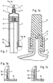
- Figure 1 shows an inventive container for injection infusion and Diagnostic preparations with a filling volume in the range between 10 and 200 ml for long-term storage and for direct administration of the filled preparations.
- the container is made up as a syringe, the Figure 1 shows the syringe in the closed state.
- the dimensions of the Containers are therefore in relation to the ratio of the total height to outer diameter to the dimensions of a commercially available syringe turned off, i.e. the ratio is greater than 2.5: 1.
- the container consists of a glass cylinder 1, the syringe cylinder, on the on the head side a converging glass head part 2 with a glass connection cone 3, the syringe head, is molded in one piece, as particularly well from the Enlarged section according to FIG. 1a can be seen.
- the connection cone 3 has a recess (groove) 4, into which a separate threaded part 5 one lockable taper connection made of plastic concentric to Connection cone to form a positive snap connection is rotatably inserted.
- the threaded part 5 takes a cap 6, preferably a rubber cap, by means of which the connecting cone 3 through Twisting the threaded part 5 to form a conical connection Cap 6 is tightly locked or locked.
- the inner contour of the Cap 6 has a contour corresponding to the outer contour of the Connection cone 3, but with an undersize in relation to the Diameter. After the cap on the connection cone 3 is pushed on or turned on, then lies the inner surface of the Sealing cap on the conical outer surface of the Connection cone 3.
- the cap also has a lining 6c elastic material that seals on the conical outer surface and rests on the end face of the connecting cone 3.
- the closure cap 6 After screwing on the threaded part 5, the closure cap 6 removed and an injection cannula or an infusion line (neither shown) - depending on the application or type of administration - on the Glass connecting cone 3 applied and by means of the loose threaded part 5 under Formation of a cone connection can be locked.
- the recess 4 is so far from the front edge of the loose threaded part 5 removed that the rubber cap 6 and later the injection cannula or a Push the infusion line sufficiently far onto the connection cone 3 can be.
- the removal of the indentation from the top of the Connection cone 3 is preferably more than 5 mm.
- the syringe barrel 1 is on the side opposite the syringe head closed with a piston plug 7, preferably made of rubber.
- This Piston plug has a connection point 8, preferably a thread, for the attachment of a syringe plunger 9.
- the Syringe barrel 1 provided on the inside with an undercut 10, in which the cylindrical extension 12 of a handle bar 13 with a complementary nose is snapped, as can be seen particularly well from Fig. 1b.
- 1c shows a special embodiment of the secure handle attachment by an inserted locking ring 13b, which is in the handle bar 13th is snapped in and secures it against being pulled out.
- the container according to the invention for long-term storage of filled preparation.
- the container can also be used as a syringe Assembled state according to FIG. 1 with the cap 6 removed and attached cannula or infusion line the preparation directly to the patient supplied by pushing it through the plunger from the container into the cannula or infusion line is displaced, the design of the container so is taken that with considerable advantage for infusion and diagnostic purposes the use of a syringe pump is made possible.
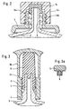
- FIG. 2 is a second embodiment of a syringe head of the Container shown according to the invention, which is in the syringe head Figure 1 differs by the design of the cap.
- cap 6a is provided with an internal thread 6b and is on the corresponding external thread 5a of the separate threaded part 5 lockable tapered connection screwed on.
- a rubber insert 14 in the middle. This is due to the sealing Shell surface and end face of the connecting cone 3. Otherwise corresponds to 2 according to FIG. 1, which is also due to the equality the reference numerals of corresponding parts are underlined.
- FIG 3 is again a special design of the syringe head on the Base shown in Figure 1.
- the recess 4 in which the threaded part 5 of lockable taper connection is snapped.
- a the cap 6 Enclosing safety cap 16 is a predetermined breaking point 17 with the Threaded part of the lockable taper connection connected.
- the safety cap 16 is equipped so that the cap 6 against accidental Pulling off secures.
- the safety cap 20 is not included illustrated profiles. Training the headboard of the Safety cap 16 is shown in more detail in Fig. 3a.
- the arc line corresponds the upper contour (break line) in Fig. 3.
- Other designs are conceivable.
- the decisive factor is the easy handling of the training.
- the smallest inside diameter of the separate threaded part 5 of the lockable Taper connection, including the contour of the snap connection, is larger than that largest outer diameter of the closure cap 6. This allows assembly of the separate threaded part with safety cap 16 even after setting Cap 6.
- FIG. 4a and 4b show a syringe head corresponding to FIG. 1, but with the difference that the cap 6 in the lower region of the Cap shirt 6d on the inner surface one or more axially extending Has grooves 15.
- the cap 6 is open on the connecting cone 3 State shown.
- the open state is characterized in that the Cap 6 not yet fully on the connecting cone 3 is pushed on, so that the groove 15 is still a connection from the environment to the inside of the syringe. This can result in the syringe be lyophilized.
- Figure 4b shows the closed state. After this The cap 6 is lyophilized completely onto the connecting cone 3 pushed so that the inner, closed conical surface 6e sealing on Connection cone 3 is present.
Landscapes
- Health & Medical Sciences (AREA)
- Hematology (AREA)
- Engineering & Computer Science (AREA)
- Anesthesiology (AREA)
- Biomedical Technology (AREA)
- Heart & Thoracic Surgery (AREA)
- Vascular Medicine (AREA)
- Life Sciences & Earth Sciences (AREA)
- Animal Behavior & Ethology (AREA)
- General Health & Medical Sciences (AREA)
- Public Health (AREA)
- Veterinary Medicine (AREA)
- Infusion, Injection, And Reservoir Apparatuses (AREA)
- Medical Preparation Storing Or Oral Administration Devices (AREA)
Claims (10)
- Récipient pour des préparations d'injection, d'infusion et de diagnostic avec un volume de remplissage de l'ordre de 10 à 200 ml pour le stockage de longue durée ainsi que pour l'administration directe des préparations, se composant d'un cylindre de verre,caractérisé en ce quedans lequel les dimensions concernant le rapport de la hauteur totale au diamètre extérieur sont adaptées aux dimensions d'une seringue du commerce (rapport supérieur à 2,5:1),sur lequel une partie de tête convergente en verre (2) est formée du côté de la tête, qui possède une pièce de fermeture à ouvrir pour l'administration dans une canule ou une conduite d'infusion,qui présente sur l'autre (côté de pied) une poignée de saisie en plastique (13), qui est fixée par un prolongement cylindrique (12) sur la paroi intérieure du cylindre de verre (1) avec un bouchon à déclic, etqui est fermé avec un bouchon servant de piston, qui présente une zone d'assemblage pour la fixation d'une tige de piston servant de tampon d'injection,sur la partie de tête convergente en verre (2) est formé d'un seul tenant un cône de raccordement (3) d'un assemblage conique, formant une tête de seringue,pour le verrouillage de l'assemblage conique, une pièce filetée séparée (5) en matière plastique est fixée de façon concentrique au cône de raccordement (3) sur la surface extérieure de celui-ci,la pièce filetée (5) est façonnée en vue de recevoir un capuchon de fermeture (6), au moyen duquel le cône de raccordement (3) peut être fermé par l'assemblage conique pour le stockage du contenu du récipient, et en vue de recevoir la canule ou la conduite d'infusion par l'assemblage conique après l'enlèvement préalable du capuchon de fermeture pour l'administration directe, et présente un capuchon de sécurité (16) sur le côté opposé au point de fixation sur la surface extérieure, la zone d'assemblage entre la pièce filetée séparée et le capuchon de sécurité constituant une zone de moindre résistance (17),la poignée de saisie (13) est fixée au cylindre de verre (1) de telle manière qu'elle résiste à des efforts d'enlèvement d'au moins 100 N, du fait que le cylindre de verre (1) présente une contre-dépouille (10) dans la zone du prolongement cylindrique (12) inséré dans la poignée de saisie (13) et que le prolongement présente une contre-dépouille complémentaire à celle-ci, formant le bouchon à déclic, et une bague de fixation (13 b) est insérée dans le prolongement cylindrique (12) de la poignée de saisie (13) et y est maintenue au moyen d'un assemblage à déclic.
- Récipient suivant la revendication 1, caractérisé en ce que le cône de raccordement (3) présente une portée tournée (4) sur sa surface latérale extérieure conique, dans une zone qui est située à plus de 5 mm de sa pointe, et en ce que la pièce filetée séparée (5) de l'assemblage conique verrouillable est introduite dans cette portée tournée (4) en formant un assemblage à déclic par emboítement.
- Récipient suivant la revendication 1, caractérisé en ce que la tête de seringue présente une portée tournée (4) dans la zone de transition entre le cône de raccordement (3) et le cylindre de seringue (1), et en ce que la pièce filetée séparée (5) de l'assemblage conique verrouillable en matière plastique est introduite dans cette portée tournée (4) en formant un assemblage à déclic par emboítement (Fig. 3).
- Récipient suivant la revendication 1, caractérisé en ce que la pièce filetée séparée (5) de l'assemblage conique verrouillable en matière plastique est collée sur la surface latérale extérieure conique du cône de raccordement (3), dans une zone qui est située à plus de 5 mm de sa pointe.
- Récipient suivant la revendication 1, caractérisé en ce que la tête de seringue présente un siège dans la zone de transition entre le cône de raccordement (3) et le cylindre de seringue (1), et en ce que la pièce filetée séparée (5) de l'assemblage conique verrouillable en matière plastique est collée sur ce siège.
- Récipient suivant l'une quelconque des revendications 1 à 5, caractérisé en ce que la pièce filetée séparée (5) de l'assemblage conique verrouillable en matière plastique présente un filet extérieur (5a), sur lequel est vissé un capuchon de fermeture (6a) en forme de couvercle avec un filet intérieur (6b), dans lequel est posé un revêtement ou un insert (14) en matière élastique, qui s'applique de façon étanche sur la surface latérale extérieure conique et/ou sur la face frontale du cône de raccordement (3) (Fig. 2).
- Récipient suivant l'une quelconque des revendications 1 à 5, caractérisé en ce que la pièce filetée séparée d'un assemblage conique verrouillable en matière plastique présente un filet intérieur, dans lequel le capuchon de fermeture est vissé avec un filet extérieur, et en ce qu'un revêtement ou un insert (6c) en matière élastique est posé dans le capuchon de fermeture, en s'appliquant de façon étanche sur la surface latérale extérieure conique et/ou sur la face frontale du cône de raccordement (3) (Fig. 1).
- Récipient suivant l'une quelconque des revendications 1 à 5, caractérisé en ce que le capuchon de fermeture (6, 6a) se compose de caoutchouc, en ce que le contour intérieur du capuchon de fermeture présente un contour correspondant au contour extérieur du cône de raccordement (3), dans lequel le contour intérieur du capuchon de fermeture présente un diamètre sous-dimensionné par rapport au contour extérieur du cône de raccordement, et en ce que le capuchon de fermeture, (6, 6a) est glissé ou tourné sur le cône de raccordement (3), la surface latérale intérieure du capuchon de fermeture s'appliquant ainsi de façon étanche sur la surface latérale extérieure conique du cône de raccordement.
- Récipient suivant les revendications 3 et 8 ou 5 et 8, caractérisé en ce que le plus petit diamètre intérieur de la pièce filetée séparée (5) de l'assemblage conique verrouillable, y compris la pièce d'assemblage à déclic ou selon le cas la face collée, est plus grand que le plus grand diamètre extérieur du capuchon de fermeture (6, 6a).
- Récipient suivant la revendication 8 ou 9, caractérisé en ce que le capuchon de fermeture (6) présente une ou plusieurs rainures axiales (15) dans la zone inférieure de la jupe du capuchon (6 d), sur la face située à l'intérieur (Fig. 4 a, b).
Applications Claiming Priority (2)
| Application Number | Priority Date | Filing Date | Title |
|---|---|---|---|
| DE4434644A DE4434644C2 (de) | 1994-09-28 | 1994-09-28 | Behältnis zur Lagerung und Verabreichung von Injektions-, Infusions- und Diagnostikpräparaten |
| DE4434644 | 1994-09-28 |
Publications (2)
| Publication Number | Publication Date |
|---|---|
| EP0707859A1 EP0707859A1 (fr) | 1996-04-24 |
| EP0707859B1 true EP0707859B1 (fr) | 2003-01-15 |
Family
ID=6529406
Family Applications (1)
| Application Number | Title | Priority Date | Filing Date |
|---|---|---|---|
| EP95109190A Expired - Lifetime EP0707859B1 (fr) | 1994-09-28 | 1995-06-14 | Récipient pour le stockage et l'administration de préparations d'injection, d'infusion et de diagnostic |
Country Status (4)
| Country | Link |
|---|---|
| US (1) | US6280418B1 (fr) |
| EP (1) | EP0707859B1 (fr) |
| JP (1) | JP3294077B2 (fr) |
| DE (2) | DE4434644C2 (fr) |
Families Citing this family (86)
| Publication number | Priority date | Publication date | Assignee | Title |
|---|---|---|---|---|
| US6196998B1 (en) * | 1994-12-12 | 2001-03-06 | Becton Dickinson And Company | Syringe and tip cap assembly |
| DE19547431A1 (de) * | 1995-12-05 | 1997-06-12 | Schering Ag | Verschlußsystem für eine sterile Spritze |
| US6006161A (en) * | 1996-08-02 | 1999-12-21 | Aisin Aw Co., Ltd. | Land vehicle navigation system with multi-screen mode selectivity |
| US5807343A (en) * | 1996-09-30 | 1998-09-15 | Becton Dickinson And Company | Protective sealing barrier for a syringe |
| DE19723851C1 (de) * | 1997-06-06 | 1998-10-08 | Schott Glas | Griffleiste für vorgefüllte Einmalspritzen |
| AT4008U1 (de) * | 1999-02-23 | 2000-12-27 | Immuno Ag | Verschlusskappe für spritzenkörper, spritzenkörper mit einer solchen verschlusskappe und kanülen-anschlussteil für eine solche verschlusskappe |
| DE10006560A1 (de) * | 2000-02-15 | 2001-08-23 | Disetronic Licensing Ag | Zweikomponentiger Kolbenstopfen |
| US20030032928A1 (en) * | 2000-03-02 | 2003-02-13 | Morihiro Sudo | Prefilled syringe assembly |
| US6569118B2 (en) * | 2000-05-25 | 2003-05-27 | Johnnie M. Johnson | Adapter and method of attachment for “LUER LOK” receptacles |
| JP2002177388A (ja) * | 2000-12-15 | 2002-06-25 | Daikyo Seiko Ltd | 医薬・医療用既充填注射器 |
| WO2002066100A2 (fr) * | 2001-02-20 | 2002-08-29 | Medrad, Inc. | Seringues, connecteurs, et ensembles seringue et connecteur s'utilisant dans des systemes d'apport de fluide |
| JP3579375B2 (ja) * | 2001-07-19 | 2004-10-20 | 株式会社トップ | ロック筒付きシリンジ |
| US6830564B2 (en) * | 2002-01-24 | 2004-12-14 | Robin Scott Gray | Syringe and method of using |
| JP2003235992A (ja) * | 2002-02-21 | 2003-08-26 | Hori Glass Kk | シリンジバレルの製造方法及びシリンジ |
| US6821267B2 (en) * | 2002-03-07 | 2004-11-23 | Baxter International | Luer tip cap having reduced removal force |
| DE10247963A1 (de) * | 2002-10-15 | 2004-05-06 | Transcoject Gesellschaft für medizinische Geräte mbH & Co KG | Membranspritze |
| DE10247965A1 (de) | 2002-10-15 | 2004-05-06 | Transcoject Gesellschaft für medizinische Geräte mbH & Co KG | Originalitätsverschluss für eine Spritze |
| DE10326706A1 (de) | 2003-06-04 | 2005-01-05 | Schott Ag | Spritze, insbesondere für medizinische Anwendungen, sowie Verfahren zum Herstellen einer solchen |
| US7442179B1 (en) * | 2003-09-23 | 2008-10-28 | Just Troy M | Pre-fill applicator |
| US20050165351A1 (en) * | 2004-01-28 | 2005-07-28 | Tamagni Henry A.Jr. | No choke cover cap |
| DE102004009919B4 (de) | 2004-02-20 | 2007-02-08 | Schott Ag | Spritze, insbesondere für medizinische Anwendungen |
| JP2006006791A (ja) * | 2004-06-29 | 2006-01-12 | Daikyo Seiko Ltd | 容器兼用注射器の注射ノズル用密封ゴム栓 |
| DE102005005468B4 (de) * | 2005-02-04 | 2006-11-02 | Arzneimittel Gmbh Apotheker Vetter & Co. Ravensburg | Spritze |
| DE102006005784B4 (de) | 2005-02-04 | 2023-09-21 | Arzneimittel Gmbh Apotheker Vetter & Co. Ravensburg | Spritze |
| DE102005037962A1 (de) | 2005-08-11 | 2007-02-15 | Arzneimittel Gmbh Apotheker Vetter & Co. Ravensburg | Spritze |
| CA2735146A1 (fr) * | 2008-08-25 | 2010-03-04 | Denki Kagaku Kogyo Kabushiki Kaisha | Seringue |
| WO2010052517A1 (fr) * | 2008-11-06 | 2010-05-14 | Becton Dickinson France | Récipient à médicaments amélioré |
| WO2010150042A1 (fr) * | 2009-06-24 | 2010-12-29 | Becton Dickinson France | Raccord luer amélioré |
| WO2011125475A1 (fr) * | 2010-03-31 | 2011-10-13 | テルモ株式会社 | Seringue |
| US9402967B1 (en) | 2010-05-27 | 2016-08-02 | Medical Device Engineering, Llc | Tamper evident cap assembly |
| US8348895B1 (en) * | 2010-05-27 | 2013-01-08 | Medical Device Engineering, LLC. | Tamper evident cap assembly |
| US8864708B1 (en) | 2010-12-03 | 2014-10-21 | Medical Device Engineering, LLC. | Tamper indicating closure assembly |
| ES2585804T3 (es) | 2010-12-16 | 2016-10-10 | Becton Dickinson France | Adaptador y dispositivo de administración de fármacos |
| US9199749B1 (en) | 2011-04-26 | 2015-12-01 | Medical Device Engineering, LLC. | Assembly and system for connecting a closure to a syringe |
| DE102011120637A1 (de) * | 2011-12-09 | 2013-06-13 | Schott Schweiz Ag | Verschluss, insdesondere Spritzenverschluss zum abdichtenden Verschließen einer distalen Öffnung eines Spritzenkörpers |
| WO2013134465A1 (fr) | 2012-03-07 | 2013-09-12 | West Pharmaceutical Services, Inc. | Dispositif de sécurité d'aiguille à faible profil radial |
| US10004854B2 (en) | 2012-03-07 | 2018-06-26 | West Pharmaceutical Services, Inc. | Low radial profile needle safety device |
| WO2013149821A1 (fr) | 2012-04-04 | 2013-10-10 | Boehringer Ingelheim International Gmbh | Système de fermeture pour pièce rapportée de dispositif d'application sur un contenant pour préparations pharmaceutiques, et utilisation, contenant doté d'un système de fermeture, seringue à usage médical et procédé de montage |
| US9311592B1 (en) | 2012-08-31 | 2016-04-12 | Medical Device Engineering, LLC. | Support and closure assembly for discharge port of a syringe and tracking system therefore |
| EP2934420B1 (fr) | 2012-12-21 | 2018-02-07 | Peter Skufca | Emballage primaire pour le stockage et/ou l'administration de composés pharmaceutiques ou médicaux |
| US9821152B1 (en) | 2013-03-04 | 2017-11-21 | Medical Device Engineering, LLC. | Closure assembly |
| EP2978480A4 (fr) * | 2013-03-28 | 2016-11-23 | Bayer Healthcare Llc | Fermeture à stérilité améliorée pour un trajet de fluide |
| CA2920684A1 (fr) | 2013-08-07 | 2015-02-12 | Unitract Syringe Pty Ltd | Adaptateurs de raccord luer pour seringues a aiguille retractable |
| CN105492054A (zh) | 2013-08-07 | 2016-04-13 | 尤尼特拉克特注射器公司 | 用于注射器的鲁尔连接适配器 |
| EP2862587A1 (fr) | 2013-10-15 | 2015-04-22 | Becton Dickinson France | Ensemble bouchon d'extrémité pour fermer un système d'injection |
| US9855191B1 (en) | 2013-12-09 | 2018-01-02 | Jonathan J. Vitello | Tamper evident shield assembly with tracking |
| US10912898B1 (en) | 2014-02-03 | 2021-02-09 | Medical Device Engineering Llc | Tamper evident cap for medical fitting |
| EP3107602B1 (fr) | 2014-02-18 | 2018-03-28 | Peter Skufca | Système d'administration pour administrer des composés médicaux ou pharmaceutiques |
| EP3107603B1 (fr) | 2014-02-18 | 2018-03-28 | Skufca, Peter | Systeme d'administration pour l'administration de composes medicaux ou pharmaceutiques |
| US10207099B1 (en) | 2014-02-21 | 2019-02-19 | Patrick Vitello | Closure assembly for medical fitting |
| US10166347B1 (en) | 2014-07-18 | 2019-01-01 | Patrick Vitello | Closure assembly for a medical device |
| WO2016034779A1 (fr) | 2014-09-05 | 2016-03-10 | Guerbet | Systeme de maintien d'un adaptateur sur un cone d'extremite d'une seringue, et ensemble comprenant un tel systeme de maintien |
| US10773067B2 (en) | 2014-09-08 | 2020-09-15 | Neomed, Inc. | Enteral connectors having coupling features |
| EP3000502A1 (fr) * | 2014-09-29 | 2016-03-30 | Becton Dickinson France | Dispositif d'administration de médicament ayant un embout revêtu |
| US10300263B1 (en) | 2015-02-27 | 2019-05-28 | Timothy Brandon Hunt | Closure assembly for a medical connector |
| US10166343B1 (en) | 2015-03-13 | 2019-01-01 | Timothy Brandon Hunt | Noise evident tamper cap |
| US10315024B1 (en) | 2015-03-19 | 2019-06-11 | Patick Vitello | Torque limiting closure assembly |
| US9592353B2 (en) * | 2015-04-30 | 2017-03-14 | Sanjay K Roy | Adaptor/tubing with alarm(s) |
| IL239366B (en) | 2015-06-11 | 2018-07-31 | Kriheli Marino | Components of a fluid transfer device |
| US11097071B1 (en) | 2016-12-14 | 2021-08-24 | International Medical Industries Inc. | Tamper evident assembly |
| US10307548B1 (en) | 2016-12-14 | 2019-06-04 | Timothy Brandon Hunt | Tracking system and method for medical devices |
| US10953162B1 (en) | 2016-12-28 | 2021-03-23 | Timothy Brandon Hunt | Tamper evident closure assembly |
| US10758684B1 (en) | 2017-03-03 | 2020-09-01 | Jonathan J. Vitello | Tamper evident assembly |
| US11040149B1 (en) | 2017-03-30 | 2021-06-22 | International Medical Industries | Tamper evident closure assembly for a medical device |
| US10888672B1 (en) | 2017-04-06 | 2021-01-12 | International Medical Industries, Inc. | Tamper evident closure assembly for a medical device |
| US10933202B1 (en) | 2017-05-19 | 2021-03-02 | International Medical Industries Inc. | Indicator member of low strength resistance for a tamper evident closure |
| US10898659B1 (en) | 2017-05-19 | 2021-01-26 | International Medical Industries Inc. | System for handling and dispensing a plurality of products |
| US11541180B1 (en) | 2017-12-21 | 2023-01-03 | Patrick Vitello | Closure assembly having a snap-fit construction |
| US11278681B1 (en) | 2018-02-20 | 2022-03-22 | Robert Banik | Tamper evident adaptor closure |
| US11413406B1 (en) | 2018-03-05 | 2022-08-16 | Jonathan J. Vitello | Tamper evident assembly |
| US11857751B1 (en) | 2018-07-02 | 2024-01-02 | International Medical Industries Inc. | Assembly for a medical connector |
| US11779520B1 (en) | 2018-07-02 | 2023-10-10 | Patrick Vitello | Closure for a medical dispenser including a one-piece tip cap |
| US11793987B1 (en) | 2018-07-02 | 2023-10-24 | Patrick Vitello | Flex tec closure assembly for a medical dispenser |
| US11690994B1 (en) | 2018-07-13 | 2023-07-04 | Robert Banik | Modular medical connector |
| US11426328B1 (en) | 2018-08-31 | 2022-08-30 | Alexander Ollmann | Closure for a medical container |
| USD948713S1 (en) | 2019-09-03 | 2022-04-12 | International Medical Industries, Inc. | Asymmetrical self righting tip cap |
| US11471610B1 (en) | 2018-10-18 | 2022-10-18 | Robert Banik | Asymmetrical closure for a medical device |
| USD903865S1 (en) | 2018-11-19 | 2020-12-01 | International Medical Industries, Inc. | Self-righting tip cap |
| US11911339B1 (en) | 2019-08-15 | 2024-02-27 | Peter Lehel | Universal additive port cap |
| US11697527B1 (en) | 2019-09-11 | 2023-07-11 | Logan Hendren | Tamper evident closure assembly |
| US11357588B1 (en) | 2019-11-25 | 2022-06-14 | Patrick Vitello | Needle packaging and disposal assembly |
| US11904149B1 (en) | 2020-02-18 | 2024-02-20 | Jonathan Vitello | Oral tamper evident closure with retained indicator |
| US11523970B1 (en) | 2020-08-28 | 2022-12-13 | Jonathan Vitello | Tamper evident shield |
| US12070591B1 (en) | 2020-12-14 | 2024-08-27 | Patrick Vitello | Snap action tamper evident closure assembly |
| US11872187B1 (en) | 2020-12-28 | 2024-01-16 | Jonathan Vitello | Tamper evident seal for a vial cover |
| CN114712622B (zh) * | 2022-04-19 | 2023-08-15 | 安徽理工大学 | 一种植入式磁力注射泵 |
Citations (3)
| Publication number | Priority date | Publication date | Assignee | Title |
|---|---|---|---|---|
| US4723945A (en) * | 1984-05-03 | 1988-02-09 | Bunder Glas Gmbh | Hypodermic syringe |
| GB2249727A (en) * | 1989-11-16 | 1992-05-20 | Duoject Inc | Syringe vial |
| EP0567186A1 (fr) * | 1992-04-21 | 1993-10-27 | Nycomed Imaging As | Pousse seringue à main |
Family Cites Families (26)
| Publication number | Priority date | Publication date | Assignee | Title |
|---|---|---|---|---|
| US2711171A (en) * | 1953-10-14 | 1955-06-21 | Becton Dickinson Co | Hypodermic syringe |
| US3055363A (en) * | 1959-11-18 | 1962-09-25 | Becton Dickinson Co | Hypodermic syringe barrel assembly |
| US3247850A (en) * | 1962-08-09 | 1966-04-26 | American Home Prod | Cartridge-syringe and needle assembly bonded together with a continuous line of adhesive |
| US3524445A (en) * | 1968-05-22 | 1970-08-18 | Becton Dickinson Co | Hypodermic syringe |
| DE1966623B2 (de) * | 1969-01-02 | 1976-08-26 | Ausscheidung aus: 19 65 761 Arias, Marcelo Chiquiar, Dr., Mexiko | Zur einmaligen benutzung bestimmte vorrichtung fuer die ausgabe einer dosis von verunreinigungsempfindlichen behandlungsfluessigkeiten |
| US3865236A (en) * | 1973-03-16 | 1975-02-11 | Becton Dickinson Co | Needle shield |
| AT360139B (de) * | 1978-10-16 | 1980-12-29 | Immuno Ag | Kombinierte ampullen-einweg-injektionsspritze |
| WO1988000479A1 (fr) * | 1986-07-11 | 1988-01-28 | Arzneimittel Gmbh Apotheker Vetter & Co. Ravensbur | Seringue pour usage medical |
| FR2563436B1 (fr) * | 1984-04-26 | 1987-06-12 | Taddei Andre | Dispositif a seringue d'injection ster ile, notamment pour les dentistes |
| US4886495A (en) * | 1987-07-08 | 1989-12-12 | Duoject Medical Systems Inc. | Vial-based prefilled syringe system for one or two component medicaments |
| US5554125A (en) * | 1987-07-08 | 1996-09-10 | Reynolds; David L. | Prefilled vial syringe |
| EP0309426A3 (fr) * | 1987-09-25 | 1991-04-03 | INDUSTRIE BORLA S.p.A. | Dispositif de fermeture étanche aux gaz, pour les embouts de tuyaux à connecter dans les appareils biomédicaux où circulent des fluides, en particulier les conduites pour hémodialyse, et qui sont stérilisés au moyen de gaz stérilisants |
| FR2633520B1 (fr) * | 1988-06-30 | 1992-04-30 | Brunel Marc | Seringue du type comportant une aiguille d'injection a usage unique, notamment pour le domaine dentaire |
| JPH0412991Y2 (fr) * | 1988-09-06 | 1992-03-27 | ||
| NZ244576A (en) * | 1989-02-08 | 1994-11-25 | Becton Dickinson Co | Syringe barrel with contrast band opposite indicia to improve readability |
| DE3916101A1 (de) * | 1989-05-17 | 1990-11-22 | Vetter & Co Apotheker | Spritze fuer medizinische zwecke |
| ES2056244T3 (es) * | 1989-05-17 | 1994-10-01 | Vetter & Co Apotheker | Jeringa para aplicaciones medicas. |
| US5067947A (en) * | 1989-07-18 | 1991-11-26 | Tri/West Systems, Inc. | Syringe plunger rod mount |
| DE3924830A1 (de) * | 1989-07-27 | 1991-02-07 | Vetter & Co Apotheker | Spritzenzylinder fuer medizinische zwecke |
| CA2016870C (fr) * | 1990-05-15 | 1994-03-29 | Arnie Drudik | Recipient distributeur servant a stocker et a melanger plusieurs elements composants |
| US5125415A (en) * | 1990-06-19 | 1992-06-30 | Smiths Industries Medical Systems, Inc. | Syringe tip cap with self-sealing filter |
| DK228290D0 (da) * | 1990-09-21 | 1990-09-21 | Novo Nordisk As | An injektion unit |
| AU661282B2 (en) * | 1990-11-14 | 1995-07-20 | Duoject Medical Systems Inc. | Syringe |
| US5224937A (en) * | 1991-06-21 | 1993-07-06 | Npbi Nederlands Produktielaboratorium Voor Bloedtransfusieapparatuur En Infusievloeistoffen B.V. | Closed syringe-filling system |
| JPH0531190A (ja) * | 1991-07-26 | 1993-02-09 | Seikagaku Kogyo Co Ltd | 注射具 |
| JP2607163Y2 (ja) * | 1993-02-18 | 2001-04-16 | 株式会社トップ | 薬液容器兼用注射器 |
-
1994
- 1994-09-28 DE DE4434644A patent/DE4434644C2/de not_active Expired - Fee Related
-
1995
- 1995-06-14 EP EP95109190A patent/EP0707859B1/fr not_active Expired - Lifetime
- 1995-06-14 DE DE59510531T patent/DE59510531D1/de not_active Expired - Fee Related
- 1995-09-26 JP JP24803995A patent/JP3294077B2/ja not_active Expired - Fee Related
-
1997
- 1997-09-02 US US08/921,665 patent/US6280418B1/en not_active Expired - Fee Related
Patent Citations (3)
| Publication number | Priority date | Publication date | Assignee | Title |
|---|---|---|---|---|
| US4723945A (en) * | 1984-05-03 | 1988-02-09 | Bunder Glas Gmbh | Hypodermic syringe |
| GB2249727A (en) * | 1989-11-16 | 1992-05-20 | Duoject Inc | Syringe vial |
| EP0567186A1 (fr) * | 1992-04-21 | 1993-10-27 | Nycomed Imaging As | Pousse seringue à main |
Also Published As
| Publication number | Publication date |
|---|---|
| DE4434644C2 (de) | 1997-08-07 |
| EP0707859A1 (fr) | 1996-04-24 |
| DE59510531D1 (de) | 2003-02-20 |
| JPH08107921A (ja) | 1996-04-30 |
| DE4434644A1 (de) | 1996-04-04 |
| US6280418B1 (en) | 2001-08-28 |
| JP3294077B2 (ja) | 2002-06-17 |
Similar Documents
| Publication | Publication Date | Title |
|---|---|---|
| EP0707859B1 (fr) | Récipient pour le stockage et l'administration de préparations d'injection, d'infusion et de diagnostic | |
| DE69723633T2 (de) | Übertragungsvorrichtung mit einem spritzlosen Ventil für Arzneimittelbehälter | |
| DE69903266T2 (de) | Flüssigkeitstransfervorrichtung für phiole und verfahren | |
| DE60019446T2 (de) | Flüssigkeitstransferset für phiolen und andere medizinische behälter | |
| DE69110290T2 (de) | Adaptor. | |
| DE3885018T2 (de) | Injektionsspritze. | |
| EP1566195B1 (fr) | Dispositif pour le stockage, le transport et l'administration d'un liquide preferablement medical | |
| DE69534359T2 (de) | Spritzenendstückkappe | |
| DE69619450T2 (de) | Wiederverschliessbare, durch eine medizinische Abgabevorrichtung aktivierbare, Behälteranordnung | |
| DE102008025011B4 (de) | Ampulle mit Ampullenhalterung | |
| DE69507920T2 (de) | Ampullenhaltevorrichtung für Arzneimittel-Injektionsstift | |
| DE2909002C3 (de) | Injektionsspritze für einmalige Verwendung | |
| CH438588A (de) | Injektionsampulle | |
| DE29602173U1 (de) | Applikationsvorrichtung für medizinische Flüssigkeiten | |
| DE1491788A1 (de) | Injektor fuer Medikamente | |
| WO1998011927A1 (fr) | Organe d'expulsion destine a faire avancer le bouchon d'une ampoule d'injection et bouchon correspondant | |
| DE2650951A1 (de) | Hypodermatische spritze | |
| EP1463552B1 (fr) | Tete de seringue a fermeture de securite | |
| DE69030117T2 (de) | Behälter für einheitsdosis | |
| DE69621994T2 (de) | Phiole mit wiederverschliessbarer Verbindungsanordnung mit Membrane und einer Flüssigkeitszugangsvorrichtung mit mehreren Konfigurationen | |
| EP1064961A1 (fr) | Seringue pour application médicale | |
| DE69715747T2 (de) | Vorrichtung zum Befüllen und zum Verabreichen des Inhalts von Spritzen | |
| EP0498376A1 (fr) | Seringue jetable autodétruisante | |
| EP3976139A1 (fr) | Corps médical creux, corps médical creux doté d'un capuchon de fermeture, procédé de fabrication d'un corps médical creux, et kit | |
| WO1997036624A1 (fr) | Seringue a usage medical |
Legal Events
| Date | Code | Title | Description |
|---|---|---|---|
| PUAI | Public reference made under article 153(3) epc to a published international application that has entered the european phase |
Free format text: ORIGINAL CODE: 0009012 |
|
| 17P | Request for examination filed |
Effective date: 19950807 |
|
| AK | Designated contracting states |
Kind code of ref document: A1 Designated state(s): CH DE FR GB IT LI |
|
| RAP1 | Party data changed (applicant data changed or rights of an application transferred) |
Owner name: CARL-ZEISS-STIFTUNG TRADING AS SCHOTT GLASWERKE Owner name: SCHOTT GLAS |
|
| RAP1 | Party data changed (applicant data changed or rights of an application transferred) |
Owner name: CARL-ZEISS-STIFTUNG TRADING AS SCHOTT GLAS Owner name: SCHOTT GLAS |
|
| 17Q | First examination report despatched |
Effective date: 19990607 |
|
| GRAH | Despatch of communication of intention to grant a patent |
Free format text: ORIGINAL CODE: EPIDOS IGRA |
|
| RTI1 | Title (correction) |
Free format text: CONTAINERS FOR STORAGE AND ADMINISTRATION OF PREPARATIONS SUITED FOR INJECTION, INFUSION OR DIAGNOSTIC PURPOSE |
|
| RTI1 | Title (correction) |
Free format text: CONTAINERS FOR STORAGE AND ADMINISTRATION OF PREPARATIONS SUITED FOR INJECTION, INFUSION OR DIAGNOSTIC PURPOSE |
|
| GRAH | Despatch of communication of intention to grant a patent |
Free format text: ORIGINAL CODE: EPIDOS IGRA |
|
| GRAA | (expected) grant |
Free format text: ORIGINAL CODE: 0009210 |
|
| AK | Designated contracting states |
Kind code of ref document: B1 Designated state(s): CH DE FR GB IT LI |
|
| REG | Reference to a national code |
Ref country code: GB Ref legal event code: FG4D Free format text: NOT ENGLISH Ref country code: CH Ref legal event code: EP |
|
| REF | Corresponds to: |
Ref document number: 59510531 Country of ref document: DE Date of ref document: 20030220 Kind code of ref document: P |
|
| GBT | Gb: translation of ep patent filed (gb section 77(6)(a)/1977) |
Effective date: 20030516 |
|
| ET | Fr: translation filed | ||
| PLBE | No opposition filed within time limit |
Free format text: ORIGINAL CODE: 0009261 |
|
| STAA | Information on the status of an ep patent application or granted ep patent |
Free format text: STATUS: NO OPPOSITION FILED WITHIN TIME LIMIT |
|
| 26N | No opposition filed |
Effective date: 20031016 |
|
| REG | Reference to a national code |
Ref country code: CH Ref legal event code: PUE Owner name: SCHOTT AG Free format text: SCHOTT GLAS#HATTENBERGSTRASSE 10#55122 MAINZ (DE) -TRANSFER TO- SCHOTT AG#HATTENBERGSTRASSE 10#55122 MAINZ (DE) |
|
| REG | Reference to a national code |
Ref country code: GB Ref legal event code: 732E |
|
| REG | Reference to a national code |
Ref country code: FR Ref legal event code: TP |
|
| PGFP | Annual fee paid to national office [announced via postgrant information from national office to epo] |
Ref country code: IT Payment date: 20090623 Year of fee payment: 15 Ref country code: FR Payment date: 20090615 Year of fee payment: 15 |
|
| PGFP | Annual fee paid to national office [announced via postgrant information from national office to epo] |
Ref country code: CH Payment date: 20090617 Year of fee payment: 15 |
|
| PGFP | Annual fee paid to national office [announced via postgrant information from national office to epo] |
Ref country code: GB Payment date: 20090618 Year of fee payment: 15 Ref country code: DE Payment date: 20090622 Year of fee payment: 15 |
|
| REG | Reference to a national code |
Ref country code: CH Ref legal event code: PL |
|
| GBPC | Gb: european patent ceased through non-payment of renewal fee |
Effective date: 20100614 |
|
| REG | Reference to a national code |
Ref country code: FR Ref legal event code: ST Effective date: 20110228 |
|
| PG25 | Lapsed in a contracting state [announced via postgrant information from national office to epo] |
Ref country code: IT Free format text: LAPSE BECAUSE OF NON-PAYMENT OF DUE FEES Effective date: 20100614 |
|
| PG25 | Lapsed in a contracting state [announced via postgrant information from national office to epo] |
Ref country code: DE Free format text: LAPSE BECAUSE OF NON-PAYMENT OF DUE FEES Effective date: 20110101 Ref country code: LI Free format text: LAPSE BECAUSE OF NON-PAYMENT OF DUE FEES Effective date: 20100630 Ref country code: CH Free format text: LAPSE BECAUSE OF NON-PAYMENT OF DUE FEES Effective date: 20100630 |
|
| PG25 | Lapsed in a contracting state [announced via postgrant information from national office to epo] |
Ref country code: FR Free format text: LAPSE BECAUSE OF NON-PAYMENT OF DUE FEES Effective date: 20100630 |
|
| PG25 | Lapsed in a contracting state [announced via postgrant information from national office to epo] |
Ref country code: GB Free format text: LAPSE BECAUSE OF NON-PAYMENT OF DUE FEES Effective date: 20100614 |