EP0707784A1 - Sämaschine für den Einsatz in der Landwirtschaft - Google Patents
Sämaschine für den Einsatz in der Landwirtschaft Download PDFInfo
- Publication number
- EP0707784A1 EP0707784A1 EP95115766A EP95115766A EP0707784A1 EP 0707784 A1 EP0707784 A1 EP 0707784A1 EP 95115766 A EP95115766 A EP 95115766A EP 95115766 A EP95115766 A EP 95115766A EP 0707784 A1 EP0707784 A1 EP 0707784A1
- Authority
- EP
- European Patent Office
- Prior art keywords
- seed
- tube
- furrow
- drill according
- tongues
- Prior art date
- Legal status (The legal status is an assumption and is not a legal conclusion. Google has not performed a legal analysis and makes no representation as to the accuracy of the status listed.)
- Granted
Links
- 210000002105 tongue Anatomy 0.000 claims abstract description 11
- 239000004033 plastic Substances 0.000 claims description 5
- 239000002184 metal Substances 0.000 claims description 4
- 230000007704 transition Effects 0.000 claims description 2
- 238000009331 sowing Methods 0.000 claims 1
- 239000002689 soil Substances 0.000 description 4
- 230000037431 insertion Effects 0.000 description 1
- 238000003780 insertion Methods 0.000 description 1
- 238000003971 tillage Methods 0.000 description 1
Images
Classifications
-
- A—HUMAN NECESSITIES
- A01—AGRICULTURE; FORESTRY; ANIMAL HUSBANDRY; HUNTING; TRAPPING; FISHING
- A01C—PLANTING; SOWING; FERTILISING
- A01C7/00—Sowing
- A01C7/20—Parts of seeders for conducting and depositing seed
- A01C7/206—Seed pipes
Definitions
- the invention relates to a seed drill for use in agriculture with a device for pulling a furrow, with a seed tube and with a seed feed tube.
- seed will pass through a seed tube into a furrow that has been drawn down.
- Seed enters the seed tube from a metering device which is equipped with a seed feed tube, the seed feed tube and the seed tube being connected to one another via a rubber hose.
- the rubber hose is connected to the two pipes via hose clamps.
- Such a connection of the two pipes is complex since at least three parts are required for this, namely two hose clamps which can be locked by hand and the rubber hose.
- the object to be achieved with the invention is seen in a simple connection of the seed tube and the seed feed tube, wherein according to a further aspect the assembly is easy and simple to carry out.
- the seed tube consists of a base tube or section which conducts the seed into the furrow and of an enlarged portion which adjoins the base tube and which is provided with tongues or tacking pins projecting inwards and in which the seed feed tube in the assembled state the tongues or tack is held.
- the rubber hose and the hose clamps can be dispensed with.
- a particularly simple insertion of the seed feed tube into the seed tube is achieved according to a further proposal in that the expanded section of the seed tube is provided with a funnel-shaped opening.
- Another proposal according to the invention provides that the widened section in the region of its transition into the base tube is provided with a part which is constricted and forms a stop for the seed feed tube.
- a fitter can easily assemble the seed tube and the seed feed tube. He only needs to insert the seed feed tube into the seed tube or vice versa until the one tube against the Stop abuts. The tongues then hold both pipes together permanently in this position. Tools are not required for this.
- the seed tube is made of metal and that the seed feed tube is made of plastic.
- the tongues or tacking pins can be triangular.
- the seed tube can be cylindrical, the base tube having a smaller inner diameter than the enlarged section.
- the seed feed tube can also be cylindrical and have an outer diameter that is slightly smaller than the inner diameter of the enlarged section of the seed tube.
- the expanded section of the seed tube is provided with four tongues or tacking pins.
- a machine for tillage in the form of a seeder is partially shown.
- a device 10 for opening a furrow which is connected to a frame part 12.
- the frame part can be part of a precision seed drill or the like, which is moved in the direction of arrow F over a field soil to be cultivated.
- Such machines and in particular the device for opening the furrows emerge from document US-A-4 760 806, to which reference is therefore made.
- An inclined furrow opener with at least one disk, which can rotate in use around an axis arranged at an angle with respect to the transverse direction, is denoted by 18 and is dragged along on a pull arm 22.
- a seed shoe 24 is arranged in the immediate vicinity of the disc of the furrow opener 18 in the shadow of the leading edge of the disc.
- the seed shoe 24 is equipped with a seed tube 24 made of metal, which is connected via a seed feed tube 28 made of plastic to a seed container (not shown in the drawing) for the metered supply of seed.
- a spring device 32 is designed such that it exerts a force directed downwards on the furrow opener 18 so that the disc of the furrow opener 18 can penetrate into the ground when used to cut a furrow 36.
- a depth control wheel 42 is rotatably provided on the outside next to the disc of the furrow opener 18, but the axis of rotation of the depth control wheel is arranged offset to the rear relative to the axis of rotation of the disc.
- the furrow depth itself is controlled by an adjusting device 44, by means of which the axis of rotation of the depth control wheel 42 can be adjusted vertically with respect to the disc of the furrow opener.
- a pressure wheel 51 for the seed and a feed wheel 52 which are mounted at the lower ends of obliquely rearward-pointing arms 53 and 54.
- the pressure wheel 51 runs in the previously pulled furrow so that the individual seeds are pressed into the furrow soil in order to maintain good contact between the seeds and the soil.
- the scraper wheel is designed to indent or collapse the furrow edges so that the seed is covered with a loose layer of soil.
- Further spring devices 55 and 56 determine the forces acting on the pressure wheel 51 and on the feed wheel 52 and directed towards the ground.
- the seed shoe 24 is provided with a metal seed tube 26.
- This seed tube extends upwards, as seen from the furrow opener 18, and consists of a base tube or section 58 for guiding the seed or, if appropriate, individual seeds into the furrow drawn through the furrow opener 18, and of an enlarged section 60, which is therefor serves to connect the seed tube 26 to the seed feed tube 28 in a simple manner.
- the seed tube 26 is cylindrical, the diameter of the enlarged section 60 being larger than that of the base tube 58.
- the enlarged section 60 of the seed tube is still at its end remote from the seed shoe with a funnel-shaped opening 62 and in the middle or approximately half height with four tongues or tacking pins 64 distributed over its inner circumference, which are triangular in shape and can be produced by corresponding incisions in the jacket of the enlarged section.
- the area in which the expanded section 60 merges into the base pipe 58 is conical, so that a stop 66 is formed here.
- the seed feed tube 28 which is made of plastic, has a diameter which corresponds approximately to that of the base tube 58 of the seed tube 26.
- a fitter only has to press or press the plastic seed feed tube into the expanded section 60 of the seed tube 26 until it comes to rest against the stop 66.
- the inwardly projecting stub pegs 64 then hold the seed feed tube firmly in this position, an extremely simple and permanent connection being produced.
Landscapes
- Life Sciences & Earth Sciences (AREA)
- Soil Sciences (AREA)
- Environmental Sciences (AREA)
- Sowing (AREA)
Abstract
Description
- Die Erfindung bezieht sich auf eine Sämaschine für den Einsatz in der Landwirtschaft mit einer Einrichtung zum Ziehen einer Furche, mit einem Saatrohr und mit einem Saatzuführrohr.
- Bei Einzelkornsämaschinen oder Sämaschinen im allgemeinen wird Saatgut in eine zum Ablegen gezogene Furche durch ein Saatrohr gelangen. In das Saatrohr gelangt Saatgut aus einer Zumeßeinrichtung, die mit einem Saatzuführrohr ausgestattet ist, wobei Saatzuführrohr und Saatrohr über einen Gummischlauch miteinander in Verbindung stehen. Der Gummischlauch ist mit den beiden Rohren über Schlauchklemmen verbunden. Eine derartige Verbindung der beiden Rohre ist aufwendig, da dazu wenigstens drei Teile benötigt werden, und zwar zwei jeweils von Hand feststellbare Schlauchklemmen und der Gummischlauch.
- Die mit der Erfindung zu lösende Aufgabe wird in einer einfachen Verbindung von Saatrohr und Saatzuführrohr gesehen, wobei nach einem weiteren Aspekt der Zusammenbau leicht und einfach auszuführen ist. Hierzu ist deshalb vorgesehen, daß das Saatrohr aus einem das Saatgut in die Furche leitenden Grundrohr oder Abschnitt und aus einem sich an das Grundrohr anschließenden erweiterten Abschnitt besteht, der mit nach innen vorstehenden Zungen oder Heftzapfen versehen ist und in dem das Saatzuführrohr im montierten Zustand durch die Zungen oder Heftzapfen gehalten ist. Auf diese Weise kann auf den Gummischlauch und die Schlauchklemmen verzichtet werden.
- Ein besonders einfaches Einführen des Saatzuführrohres in das Saatrohr wird nach einem weiteren Vorschlag dadurch erreicht, daß der erweiterte Abschnitt des Saatrohres mit einer trichterförmigen Öffnung versehen ist.
- Ein weiterer erfindungsgemäßer Vorschlag sieht vor, daß der erweiterte Abschnitt im Bereich seines Übergangs in das Grundrohr mit einem eingeschnürten und einen Anschlag für das Saatzuführrohr bildenden Teil versehen ist. Auf diese Weise kann ein Monteur das Saatrohr und das Saatzuführrohr leicht zusammenfügen. Er braucht lediglich das Saatzuführrohr in das Saatrohr zu stecken bzw. umgekehrt, bis daß das eine Rohr gegen den Anschlag anstößt. Die Zungen halten dann in dieser Lage beide Rohre dauerhaft zusammen. Werkzeuge sind hierzu nicht erforderlich.
- Von Vorteil ist es, wenn das Saatrohr aus Metall und daß das Saatzuführrohr aus Kunststoff besteht.
- Die Zungen oder Heftzapfen können dreieckförmig ausgebildet sein.
- Im einzelnen kann das Saatrohr zylindrisch ausgebildet sein, wobei das Grundrohr einen kleineren Innendurchmesser als der erweiterte Abschnitt aufweist. Auch das Saatzuführrohr kann zylindrisch ausgebildet sein und einen Außendurchmesser aufweisen, der geringfügig kleiner ist als der Innendurchmesser des erweiterten Abschnittes des Saatrohres.
- Zweckmäßig ist es, wenn der erweiterte Abschnitt des Saatrohres mit vier Zungen oder Heftzapfen versehen ist.
- In der Zeichnung ist ein nachfolgend näher erläutertes Ausführungsbeispiel der Erfindung dargestellt. Es zeigt:
- Fig. 1
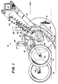
- eine Einrichtung zum Öffnen einer Saatfurche an einer nicht weiter dargestellten Sämaschine mit einem Saatrohr und einem Saatzuführrohr, die selbsthemmend miteinander verbunden sind,
- Fig. 2
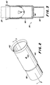
- einen erweiterten Abschnitt des Saatrohres in perspektivischer Darstellung und
- Fig. 3
- das mit dem Saatzuführrohr zusammengefügte Saatrohr im Querschnitt.
- In Fig. 1 der Zeichnung ist eine Maschine für die Bodenbestellung in Form einer Sämaschine teilweise dargestellt. Man erkennt eine Einrichtung 10 zum Öffnen einer Furche, die an einem Rahmenteil 12 angeschlossen ist. Der Rahmenteil kann Teil einer Einzelkornsämaschine oder dergleichen sein, die über einen zu bestellenden Ackerboden in Richtung des Pfeils F fortbewegt wird. Derartige Maschinen und insbesondere die Einrichtung zum Furchenöffnen gehen aus dem Dokument US-A-4 760 806 hervor, auf das deshalb Bezug genommen wird. Ein schräg stehender Furchenöffner mit wenigstens einer Scheibe, die um eine mit Bezug auf die Querrichtung winklig angeordnete Achse im Einsatz umlaufen kann, ist mit 18 bezeichnet und an einem Zugarm 22 nachschleppend angeordnet. Ein Saatschuh 24 ist in unmittelbarer Nähe der Scheibe des Furchenöffners 18 im Schatten der vorlaufenden Kante der Scheibe angeordnet. Der Saatschuh 24 ist mit einem Saatrohr 24 aus Metall ausgestattet, das über ein Saatzuführrohr 28 aus Kunststoff mit einem in der Zeichnung nicht dargestellten Saatgutbehälter zur dosierten Zufuhr von Saatgut verbunden ist.
- Eine Federeinrichtung 32 ist derart ausgebildet, daß sie auf den Furchenöffner 18 eine bodenwärts gerichtete Kraft ausübt, damit die Scheibe des Furchenöffners 18 im Einsatz zum Schneiden einer Furche 36 in den Boden eindringen kann. Ein Tiefensteuerrad 42 ist außen neben der Scheibe des Furchenöffners 18 drehbar vorgesehen, wobei jedoch die Drehachse des Tiefensteuerrades gegenüber der Drehachse der Scheibe nach rückwärts versetzt angeordnet ist. Die Furchentiefe selbst wird dabei über eine Einstellvorrichtung 44 kontrolliert, über die die Drehachse des Tiefensteuerrades 42 vertikal gegenüber der Scheibe des Furchenöffners verstellt werden kann.
- Rückwärtig der Scheibe des Furchenöffners 18 sind noch ein Andrückrad 51 für das Saatgut und ein Zustreichrad 52 vorgesehen, die an den unteren Enden von schräg nach rückwärts gerichteten Armen 53 und 54 gelagert sind. Während des Einsatzes läuft das Andrückrad 51 in der zuvor gezogenen Furche, damit das einzelne Saatgut in den Furchenboden gedrückt wird, um einen guten Kontakt des Saatgutes mit dem Erdreich zu erhalten. Das Zustreichrad ist dazu bestimmt, die Furchenränder einzudrücken oder einstürzen zu lassen, damit das Saatgut mit einer lockeren Schicht Erdreich bedeckt wird. Weitere Federeinrichtungen 55 und 56 bestimmen die auf das Andrückrad 51 und auf das Zustreichrad 52 wirkenden und bodenwärts gerichteten Kräfte.
- Es wurde bereits vorstehend darauf verwiesen, daß der Saatschuh 24 mit einem Saatrohr 26 aus Metall versehen ist. Dieses Saatrohr erstreckt sich, von dem Furchenöffner 18 aus gesehen, nach oben und besteht aus einem Grundrohr oder Abschnitt 58, um das Saatgut oder gegebenenfalls einzelne Saatkörner in die durch den Furchenöffner 18 gezogenen Furche zu lenken, und aus einem erweiterten Abschnitt 60, der dazu dient, das Saatrohr 26 in einfacher Weise mit dem Saatzuführrohr 28 zu verbinden. Das Saatrohr 26 ist dabei zylindrisch ausgebildet, wobei der Durchmesser des erweiterten Abschnittes 60 größer ist als der des Grundrohres 58. Außerdem ist der erweiterte Abschnitt 60 des Saatrohres an seinem dem Saatschuh abgelegenen Ende noch mit einer trichterförmigen Öffnung 62 und in seiner Mitte oder etwa auf halber Höhe mit vier auf seinem inneren Umfang verteilten Zungen oder Heftzapfen 64 versehen, die dreieckförmig ausgebildet und durch entsprechende Einschnitte in den Mantel des erweiterten Abschnittes hergestellt werden können. Der Bereich, in dem der erweiterte Abschnitt 60 in das Grundrohr 58 übergeht, ist kegelig gestaltet, so daß hier ein Anschlag 66 entsteht.
- Das aus Kunststoff bestehende Saatzuführrohr 28 weist einen Durchmesser auf, der in etwa dem des Grundrohres 58 des Saatrohres 26 entspricht. Um nun beide Rohre, d. h. das Saatrohr und das Saatzuführrohr miteinander verbinden zu können, muß ein Monteur das aus Kunststoff bestehende Saatzuführrohr lediglich in den erweiterten Abschnitt 60 des Saatrohres 26 drücken oder pressen, bis es gegen den Anschlag 66 zu liegen kommt. Die nach innen vorstehenden Heftzapfen 64 halten dann in dieser Stellung das Saatzuführrohr fest, wobei eine äußerst einfache und dauerhafte Verbindung entsteht.
Claims (8)
- Sämaschine für den Einsatz in der Landwirtschaft mit einer Einrichtung (10) zum Ziehen einer Furche (36), mit einem Saatrohr (26) und mit einem Saatzuführrohr (28), dadurch gekennzeichnet, daß das Saatrohr (26) aus einem das Saatgut in die Furche (36) leitenden Grundrohr oder Abschnitt (58) und aus einem sich an das Grundrohr (58) anschließenden erweiterten Abschnitt (60) besteht, der mit nach innen vorstehenden Zungen oder Heftzapfen (64) versehen ist und in dem das Saatzuführrohr (28) im montierten Zustand durch die Zungen oder Heftzapfen (64) gehalten ist.
- Sämaschine nach Anspruch 1, dadurch gekennzeichnet, daß der erweiterte Abschnitt (60) des Saatrohres (26) mit einer trichterförmigen Öffnung (62) versehen ist.
- Sämaschine nach Anspruch 1 oder 2, dadurch gekennzeichnet, daß der erweiterte Abschnitt (60) im Bereich seines Übergangs in das Grundrohr (58) mit einem eingeschürten und einen Anschlag (66) für das Saatzuführrohr (28) bildenden Teil versehen ist.
- Sämaschine nach einem oder mehreren der vorherigen Ansprüche, dadurch gekennzeichnet, daß das Saatrohr (26) aus Metall und daß das Saatzuführrohr (28) aus Kunststoff besteht.
- Sämaschine nach Anspruch 1, dadurch gekennzeichnet, daß die Zungen oder Heftzapfen (64) dreieckförmig ausgebildet sind.
- Sämaschine nach einem oder mehreren der vorherigen Ansprüche, dadurch gekennzeichnet, daß das Saatrohr (26) zylindrisch ausgebildet ist, wobei das Grundrohr (58) einen kleineren Innendurchmesser als der erweiterte Abschnitt (60) aufweist.
- Sämaschine nach Anspruch 6, dadurch gekennzeichnet, daß das Saatzuführrohr (28) zylindrisch ausgebildet ist und einen Außendurchmesser aufweist, der geringfügig kleiner ist als der Innendurchmesser des erweiterten Abschnittes (60) des Saatrohres (26).
- Sämaschine nach Anspruch 5, dadurch gekennzeichnet, daß der erweiterte Abschnitt (60) des Saatrohres (26) mit vier Zungen oder Heftzapfen (64) versehen ist.
Applications Claiming Priority (2)
| Application Number | Priority Date | Filing Date | Title |
|---|---|---|---|
| US08/324,042 US5542363A (en) | 1994-10-17 | 1994-10-17 | Self locking seed tube |
| US324042 | 1994-10-17 |
Publications (3)
| Publication Number | Publication Date |
|---|---|
| EP0707784A1 true EP0707784A1 (de) | 1996-04-24 |
| EP0707784B1 EP0707784B1 (de) | 1997-06-18 |
| EP0707784B2 EP0707784B2 (de) | 2000-12-06 |
Family
ID=23261821
Family Applications (1)
| Application Number | Title | Priority Date | Filing Date |
|---|---|---|---|
| EP95115766A Expired - Lifetime EP0707784B2 (de) | 1994-10-17 | 1995-10-06 | Sämaschine für den Einsatz in der Landwirtschaft |
Country Status (6)
| Country | Link |
|---|---|
| US (1) | US5542363A (de) |
| EP (1) | EP0707784B2 (de) |
| AU (1) | AU686854B2 (de) |
| BR (1) | BR9504399A (de) |
| DE (1) | DE59500326D1 (de) |
| ES (1) | ES2103143T5 (de) |
Cited By (2)
| Publication number | Priority date | Publication date | Assignee | Title |
|---|---|---|---|---|
| EP2022307A1 (de) * | 2007-08-03 | 2009-02-11 | Amazonen-Werke H. Dreyer GmbH & Co. KG | Säschar |
| DE102021110994A1 (de) | 2021-04-29 | 2022-11-03 | Horsch Maschinen Gmbh | Säschar sowie Sämaschine und Verfahren zum Ausbringen von Saatgut und/oder Dünger |
Families Citing this family (7)
| Publication number | Priority date | Publication date | Assignee | Title |
|---|---|---|---|---|
| US6332413B1 (en) | 1995-12-29 | 2001-12-25 | Case Corporation | Seed tube for seed metering apparatus |
| US5931105A (en) * | 1998-12-04 | 1999-08-03 | Deere & Company | Sensor plugs for a seed tube |
| US6209466B1 (en) | 1999-05-12 | 2001-04-03 | Deere & Company | Two piece seed boot for a seeding machine |
| US6634678B2 (en) | 2001-03-20 | 2003-10-21 | Deere & Co. | Seed conduit detachable coupler having a seed cut off |
| US7152540B1 (en) * | 2005-08-19 | 2006-12-26 | Precision Planting, Inc. | Seed tube for an agricultural planter |
| US8499703B2 (en) | 2010-12-08 | 2013-08-06 | Matthew P. Hagny | Seed tube mounting assembly for agricultural seeder |
| US9061251B2 (en) * | 2011-09-27 | 2015-06-23 | Markel Corporation | Self sealing membrane contactor with PTFE tubular membranes |
Citations (4)
| Publication number | Priority date | Publication date | Assignee | Title |
|---|---|---|---|---|
| US3804036A (en) * | 1972-10-05 | 1974-04-16 | E Seifert | Air induction apparatus for seed drill tube |
| DE3416219A1 (de) * | 1984-05-02 | 1985-11-07 | Arnold 3167 Burgdorf Jäger | Rohrartige verbindung zwischen dem vorratsbehaelter und dem verteiler an drillmaschinen |
| US4760806A (en) | 1986-05-22 | 1988-08-02 | Deere & Company | Conservation opener |
| DE3701217A1 (de) * | 1987-01-17 | 1988-08-04 | Rabewerk Clausing Heinrich | Bausatz mit einer saemaschine und austauschbaren saescharkoerpern |
Family Cites Families (13)
| Publication number | Priority date | Publication date | Assignee | Title |
|---|---|---|---|---|
| US216851A (en) * | 1879-06-24 | Improvement in hose-couplings | ||
| US599492A (en) * | 1898-02-22 | Switch and signal connection | ||
| US442837A (en) * | 1890-12-16 | Pipe-coupling | ||
| GB190302030A (en) * | 1903-01-28 | 1903-11-26 | James Gresham Barber | Improvements in Couplings for Metal Tubes Containing Electric Wires |
| US1160611A (en) * | 1912-12-03 | 1915-11-16 | Harry L Hudson | Sheet-metal box. |
| US1851404A (en) * | 1931-02-13 | 1932-03-29 | Anton J Rose | Ball for fence posts, poles, etc. |
| US2359117A (en) * | 1943-01-25 | 1944-09-26 | Homer E Johnson | Handle lock |
| US2861527A (en) † | 1955-05-23 | 1958-11-25 | Thermoid Company | Seeding and fertilizing device and hose securing means therefor |
| DD98566A1 (de) † | 1972-08-08 | 1973-06-20 | ||
| US4064614A (en) * | 1976-12-23 | 1977-12-27 | Samuel Moore And Company | Method of making an improved hose and tube coupling |
| US4522340A (en) † | 1983-07-01 | 1985-06-11 | Gandy Company | Granular material applicator with speed compensator |
| US5092255A (en) * | 1991-01-22 | 1992-03-03 | Deere & Company | Seed boot extension |
| US5398981A (en) * | 1993-01-04 | 1995-03-21 | Modine Manufacturing Company | Self-centering, self-seating, double-sealing, intereference fit tube joint |
-
1994
- 1994-10-17 US US08/324,042 patent/US5542363A/en not_active Expired - Lifetime
-
1995
- 1995-09-05 AU AU30467/95A patent/AU686854B2/en not_active Ceased
- 1995-10-06 EP EP95115766A patent/EP0707784B2/de not_active Expired - Lifetime
- 1995-10-06 ES ES95115766T patent/ES2103143T5/es not_active Expired - Lifetime
- 1995-10-06 DE DE59500326T patent/DE59500326D1/de not_active Expired - Lifetime
- 1995-10-13 BR BR9504399A patent/BR9504399A/pt not_active IP Right Cessation
Patent Citations (4)
| Publication number | Priority date | Publication date | Assignee | Title |
|---|---|---|---|---|
| US3804036A (en) * | 1972-10-05 | 1974-04-16 | E Seifert | Air induction apparatus for seed drill tube |
| DE3416219A1 (de) * | 1984-05-02 | 1985-11-07 | Arnold 3167 Burgdorf Jäger | Rohrartige verbindung zwischen dem vorratsbehaelter und dem verteiler an drillmaschinen |
| US4760806A (en) | 1986-05-22 | 1988-08-02 | Deere & Company | Conservation opener |
| DE3701217A1 (de) * | 1987-01-17 | 1988-08-04 | Rabewerk Clausing Heinrich | Bausatz mit einer saemaschine und austauschbaren saescharkoerpern |
Cited By (2)
| Publication number | Priority date | Publication date | Assignee | Title |
|---|---|---|---|---|
| EP2022307A1 (de) * | 2007-08-03 | 2009-02-11 | Amazonen-Werke H. Dreyer GmbH & Co. KG | Säschar |
| DE102021110994A1 (de) | 2021-04-29 | 2022-11-03 | Horsch Maschinen Gmbh | Säschar sowie Sämaschine und Verfahren zum Ausbringen von Saatgut und/oder Dünger |
Also Published As
| Publication number | Publication date |
|---|---|
| ES2103143T5 (es) | 2001-02-16 |
| US5542363A (en) | 1996-08-06 |
| AU3046795A (en) | 1996-05-02 |
| DE59500326D1 (de) | 1997-07-24 |
| ES2103143T3 (es) | 1997-08-16 |
| EP0707784B2 (de) | 2000-12-06 |
| BR9504399A (pt) | 1997-05-27 |
| EP0707784B1 (de) | 1997-06-18 |
| AU686854B2 (en) | 1998-02-12 |
Similar Documents
| Publication | Publication Date | Title |
|---|---|---|
| DE2640749C3 (de) | Drillmaschine | |
| EP0264711B1 (de) | Bodenbearbeitungsgerät | |
| DE2211457C3 (de) | Pflanzwerkzeug für Sämlinge | |
| EP1135980A1 (de) | Sämaschine und pneumatisches Reduzierelement | |
| EP0707784B1 (de) | Sämaschine für den Einsatz in der Landwirtschaft | |
| DE3216376C2 (de) | Drillmaschine für das Direktsaatverfahren zum Ausbringen von Saatgut und Düngemitteln | |
| EP0764395A1 (de) | Verfahren zum Anschliessen eines Bodenbearbeitungswerkzeugs an einen Befestigungsschaft und Ausbildung von Bodenbearbeitungswerkzeug und Befestigungsschaft zum Durchführen dieses Verfahrens | |
| DD297298A5 (de) | Vorrichtung zum einbringen von samen in den boden | |
| DE2310805A1 (de) | Saemaschine | |
| DE2659523C2 (de) | Sämaschine | |
| DE20304258U1 (de) | Vorrichtung für eine Landwirtschaftsmaschine | |
| EP0311833B1 (de) | Sämaschine | |
| DE60106677T2 (de) | Sämaschine | |
| EP0170825B1 (de) | Vorsatzscharkörper | |
| DE2010855B2 (de) | Maschine zum ausbringen von saatgut und duengemitteln | |
| DE69606203T2 (de) | Sähmaschine | |
| DE812219C (de) | Vorrichtung fuer das Setzen von Pflanzen | |
| DE69407113T2 (de) | Pneumatischer Sämaschine und kombinierte Landmaschine zur Bodenbearbeitung und zum Säen mit einer solchen pneumatischen Sämaschine | |
| DE2227018C3 (de) | Pflanzvorrichtung | |
| DE2456200A1 (de) | Zahn fuer eine egge | |
| DE2814133B1 (de) | Mit einem Anbaurahmen versehene Saeeinrichtung | |
| DE3903472A1 (de) | Kombinierte landwirtschaftliche verteilmaschine | |
| EP4173457A1 (de) | Anordnung mit einem arbeitswerkzeug zur bodenbearbeitung für eine landwirtschaftliche maschine sowie landwirtschaftliche maschine | |
| DE2063225A1 (de) | Schargehause fur Sämaschinen | |
| EP1820381A1 (de) | Sämaschine zum reihenweisen Einbringen von Saatgut in den Boden |
Legal Events
| Date | Code | Title | Description |
|---|---|---|---|
| PUAI | Public reference made under article 153(3) epc to a published international application that has entered the european phase |
Free format text: ORIGINAL CODE: 0009012 |
|
| 17P | Request for examination filed |
Effective date: 19960205 |
|
| AK | Designated contracting states |
Kind code of ref document: A1 Designated state(s): DE ES FR IT |
|
| GRAG | Despatch of communication of intention to grant |
Free format text: ORIGINAL CODE: EPIDOS AGRA |
|
| GRAH | Despatch of communication of intention to grant a patent |
Free format text: ORIGINAL CODE: EPIDOS IGRA |
|
| 17Q | First examination report despatched |
Effective date: 19960924 |
|
| GRAH | Despatch of communication of intention to grant a patent |
Free format text: ORIGINAL CODE: EPIDOS IGRA |
|
| GRAA | (expected) grant |
Free format text: ORIGINAL CODE: 0009210 |
|
| AK | Designated contracting states |
Kind code of ref document: B1 Designated state(s): DE ES FR IT |
|
| REF | Corresponds to: |
Ref document number: 59500326 Country of ref document: DE Date of ref document: 19970724 |
|
| ET | Fr: translation filed | ||
| REG | Reference to a national code |
Ref country code: ES Ref legal event code: FG2A Ref document number: 2103143 Country of ref document: ES Kind code of ref document: T3 |
|
| PLBI | Opposition filed |
Free format text: ORIGINAL CODE: 0009260 |
|
| PLBF | Reply of patent proprietor to notice(s) of opposition |
Free format text: ORIGINAL CODE: EPIDOS OBSO |
|
| 26 | Opposition filed |
Opponent name: AMAZONEN-WERKE H. DREYER GMBH & CO. KG Effective date: 19980307 |
|
| PLBF | Reply of patent proprietor to notice(s) of opposition |
Free format text: ORIGINAL CODE: EPIDOS OBSO |
|
| PLBQ | Unpublished change to opponent data |
Free format text: ORIGINAL CODE: EPIDOS OPPO |
|
| PLAB | Opposition data, opponent's data or that of the opponent's representative modified |
Free format text: ORIGINAL CODE: 0009299OPPO |
|
| R26 | Opposition filed (corrected) |
Opponent name: AMAZONEN-WERKE H. DREYER GMBH & CO. KG Effective date: 19980307 |
|
| PLAW | Interlocutory decision in opposition |
Free format text: ORIGINAL CODE: EPIDOS IDOP |
|
| PLAW | Interlocutory decision in opposition |
Free format text: ORIGINAL CODE: EPIDOS IDOP |
|
| PUAH | Patent maintained in amended form |
Free format text: ORIGINAL CODE: 0009272 |
|
| STAA | Information on the status of an ep patent application or granted ep patent |
Free format text: STATUS: PATENT MAINTAINED AS AMENDED |
|
| ITF | It: translation for a ep patent filed | ||
| 27A | Patent maintained in amended form |
Effective date: 20001206 |
|
| AK | Designated contracting states |
Kind code of ref document: B2 Designated state(s): DE ES FR IT |
|
| ET3 | Fr: translation filed ** decision concerning opposition | ||
| REG | Reference to a national code |
Ref country code: ES Ref legal event code: DC2A Kind code of ref document: T5 Effective date: 20010110 |
|
| PGFP | Annual fee paid to national office [announced via postgrant information from national office to epo] |
Ref country code: ES Payment date: 20041110 Year of fee payment: 10 |
|
| PG25 | Lapsed in a contracting state [announced via postgrant information from national office to epo] |
Ref country code: IT Free format text: LAPSE BECAUSE OF NON-PAYMENT OF DUE FEES;WARNING: LAPSES OF ITALIAN PATENTS WITH EFFECTIVE DATE BEFORE 2007 MAY HAVE OCCURRED AT ANY TIME BEFORE 2007. THE CORRECT EFFECTIVE DATE MAY BE DIFFERENT FROM THE ONE RECORDED. Effective date: 20051006 |
|
| PG25 | Lapsed in a contracting state [announced via postgrant information from national office to epo] |
Ref country code: ES Free format text: LAPSE BECAUSE OF NON-PAYMENT OF DUE FEES Effective date: 20051007 |
|
| REG | Reference to a national code |
Ref country code: ES Ref legal event code: FD2A Effective date: 20051007 |
|
| PGFP | Annual fee paid to national office [announced via postgrant information from national office to epo] |
Ref country code: FR Payment date: 20101105 Year of fee payment: 16 |
|
| REG | Reference to a national code |
Ref country code: FR Ref legal event code: ST Effective date: 20120629 |
|
| PG25 | Lapsed in a contracting state [announced via postgrant information from national office to epo] |
Ref country code: FR Free format text: LAPSE BECAUSE OF NON-PAYMENT OF DUE FEES Effective date: 20111102 |
|
| PGFP | Annual fee paid to national office [announced via postgrant information from national office to epo] |
Ref country code: DE Payment date: 20121102 Year of fee payment: 18 |
|
| REG | Reference to a national code |
Ref country code: DE Ref legal event code: R119 Ref document number: 59500326 Country of ref document: DE Effective date: 20140501 |
|
| PG25 | Lapsed in a contracting state [announced via postgrant information from national office to epo] |
Ref country code: DE Free format text: LAPSE BECAUSE OF NON-PAYMENT OF DUE FEES Effective date: 20140501 |