EP0706881B1 - Système de guidage de feuilles dans le dispositif de retournement d'une machine à imprimer recto-verso - Google Patents
Système de guidage de feuilles dans le dispositif de retournement d'une machine à imprimer recto-verso Download PDFInfo
- Publication number
- EP0706881B1 EP0706881B1 EP95113345A EP95113345A EP0706881B1 EP 0706881 B1 EP0706881 B1 EP 0706881B1 EP 95113345 A EP95113345 A EP 95113345A EP 95113345 A EP95113345 A EP 95113345A EP 0706881 B1 EP0706881 B1 EP 0706881B1
- Authority
- EP
- European Patent Office
- Prior art keywords
- sheet
- sheet guiding
- cylinder
- blowing
- turning
- Prior art date
- Legal status (The legal status is an assumption and is not a legal conclusion. Google has not performed a legal analysis and makes no representation as to the accuracy of the status listed.)
- Expired - Lifetime
Links
Images
Classifications
-
- B—PERFORMING OPERATIONS; TRANSPORTING
- B41—PRINTING; LINING MACHINES; TYPEWRITERS; STAMPS
- B41F—PRINTING MACHINES OR PRESSES
- B41F21/00—Devices for conveying sheets through printing apparatus or machines
- B41F21/10—Combinations of transfer drums and grippers
- B41F21/106—Combinations of transfer drums and grippers for reversing sheets, e.g. for perfecting machine
- B41F21/108—Combinations of transfer drums and grippers for reversing sheets, e.g. for perfecting machine with pneumatic means
Definitions
- the invention relates to a sheet guide module in a turning device for a rotary printing press that can be used for face and reverse printing, the turning device being formed from a turning drum and at least one sheet-guiding cylinder arranged upstream in the sheet running direction between two printing units.
- a sheet-guiding turning device of this type is known from DE-AS 2 354 418.
- Three drums for sheet transfer are arranged between two printing units of a rotary printing press, a drum being designed as a reversing drum assigned to the subsequent printing unit in the direction of sheet travel.
- the turning drum is preceded by a transfer drum which has flow channels which are arranged axially on the circumference at a defined distance and run in the form of grooves and acted upon by suction air.
- This solution is intended to provide tension-free, tight support of the sheet on a transfer drum so that the sheet can be transferred to the turning drum in a fitting manner.
- the reversing drum and transfer drum are not assigned any devices that guarantee a lubrication-free sheet guidance of the freely hanging end of the printing sheet in the turning phase.
- a sheet transfer cylinder is known, in which the sheet is held at the beginning and end by grippers and is sucked onto the circumference of the sheet transfer cylinder by negative air pressure.
- the sheet should thus lie flat and be drawn smooth towards the end of the sheet.
- the transfer cylinder is for the guidance of a free-hanging sheet is unsuitable due to the arrangement of grippers on the rear edge.
- EP 0 306 684 B1 a device for pressing a sheet flat against the printing cylinder is described. After passing through the printing zone, the sheet is guided in the area between the printing zone and the transfer area (tangent point) of the subsequent turning drum by means of blown air on the printing cylinder.
- a sheet guiding device as a continuous guide surface which has air nozzles connected to flow channels is known, for. B. known from DE 3 411 029 C2.
- a device for sheet guiding which lifts the sheet leading edge during the turning phase by means of blown air from the impression cylinder and guides the front part of the sheet on a guide doctor.
- a disadvantage of these solutions is that in the turning phase in which the sheet undergoes a reversal of movement, there are insufficient means available to transport the printed sheet without smearing from the upstream sheet-guiding cylinder, a printing cylinder or a storage drum, to the turning drum.
- the object of the invention is to develop a solution which guarantees a smear-free sheet guide, in particular the freely hanging trailing edge, of printed sheets which are turned according to the principle of trailing edge use during the turning phase in a rotary printing press.
- the invention has the advantage that, in particular, the freely hanging, rear region of a turned sheet is prevented from smearing, so that an improvement in the print quality is achieved.
- the solution according to the invention is suitable for rotary printing presses which operate on the principle of turning trailing edges and have one or three sheet-guiding drums / cylinders between the printing units.
- the blowing device When arranging a sheet-guiding drum, the blowing device is assigned to the upstream pressure cylinder. With the arrangement of three sheet-guiding drums, the blowing device is assigned to the upstream storage drum.
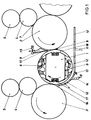
- a turning device is arranged between two printing units.
- the upstream printing unit is formed in a known manner by a printing cylinder 2, a blanket cylinder 4 and a plate cylinder 5.
- the printing unit following in the sheet running direction of the turning device is formed by a printing cylinder 3, a blanket cylinder 4 and a plate cylinder 5.
- the inking and dampening units assigned to the plate cylinder 5 are not shown.
- the sheet-guiding cylinders, here the impression cylinders 2, 3, are of double size and the turning device is essentially formed by a double-size turning drum 1.
- the turning drum 1 carries on each half a gripping device 6 arranged offset by 180 °.
- the gripping device 6 consists in a known manner of a suction system, a counterpressure gripper system and a straight-pressure gripper system with corresponding gripper supports.
- the sheet guiding module essentially consists of a blowing device 9, two blowing / suction devices 16 integrated in the turning drum 1 and a sheet guiding device 12.
- the blowing device 9 is after a printing zone 7 formed by printing cylinder 2 and blanket cylinder 4, but before a transfer area 8 (formed by Printing cylinder 2 and turning drum 1) the printing cylinder 2 over its length assigned.
- the blowing device 9 has air outlet openings which are adapted to the contour of the printing cylinder 2. The air outlet openings extend as far as the transfer area 8.
- the blowing device 9 furthermore has at least one separate air outlet opening 10 which is directed tangentially into the transfer area 8.
- the air outlet openings 10 are subjected to a higher air pressure than the outlet openings which are directed onto the pressure cylinder 2.
- the blowing device 9 thus has two supply lines for the supply of compressed air with different intensities and is pivotably mounted in a swivel joint 15 from the transfer area 8.
- each circumferential surface has a plurality of air openings, e.g. Bores, which are preferably arranged at regular intervals.
- Each blowing / suction device 16 is coupled to a pneumatic system 17.
- the pneumatic system 17 can consist, for example, of fans arranged in the turning drum or an external air supply.
- the external air supply is preferably coupled to the blowing / suction devices 16 by means of a rotary transformer.
- a sheet guiding device 12 is arranged between the turning drum 1 and the upstream sheet-guiding printing cylinder 2.
- the sheet guiding device 12 is connected to an external air supply source via a line system 11.
- the part of the sheet guiding device 12 which is assigned to the arc riser receives its air supply via fans.
- This part of the sheet guiding device 12 is coupled to a swivel joint 13 and can be pivoted about the pivot point of the swivel joint 13 via a working cylinder 14.
- the mode of action is as follows: In perfecting, the sheet which is guided on the printing cylinder 2 through the printing zone 7 is pressed flat onto the printing cylinder 2 by means of air from the blowing device 9. The sheet is fed into the transfer area 8 up to the rear edge. The separate air outlet opening 10 of the blowing device 9 blows tangentially against the rear edge of the sheet, so that the rear area of the sheet is separated from the printing cylinder 2 after passing through the transfer area 8.
- the sheet released by the gripper system of the printing cylinder is taken over by the gripping device 6 of the turning drum 1 according to the principle of turning the rear edge (turning phase). The trailing edge of the sheet thus becomes the leading edge on the turning drum 1 and is transferred to the impression cylinder 3 for the back printing.
- the turning phase is a critical area, since the sheet has to be "peeled off” from the impression cylinder 2 in a very short time, the former leading edge (reversal of movement) becomes the freely hanging trailing edge and the printed, sagging surface of the sheet is inclined to be lubricated.
- the “peeling” is achieved by the air flow of the separate air outlet opening 10.
- An air cushion is thus inserted between the trailing edge of the sheet and the impression cylinder, which reduces the adhesive force of the sheet and the sliding friction (between the sheet and impression cylinder) during the turning phase.
- the sheet guiding device 12 blows air against the printed surface of the sheet, the separate air outlet opening 10 of the blowing device 9 continuing to blow air through the transfer area 8.
- the generation of negative pressure below the transfer area 8 is to be avoided.
- the sheet taken over from the turning drum 1 is thus guided in its free area on the printed and the unprinted surface (from above and below) by means of air.
- the sheet is attracted by the sucking blowing / suction device 16 and lies against the circumference of the turning drum 1 with the unprinted surface.
- the arc following the circumference of the turning drum 1 has a slight convex curvature, which additionally has a stabilizing effect on the rear, still freely hanging area of the arc.
- the sheet guiding device 12 in the sheet rise to the downstream printing cylinder 3 can be pivoted via the working cylinder 14 depending on the operating mode.
- the sheet guided on the printing cylinder 2 through the printing zone 7 is transferred to the turning drum 1 with the leading edge in the transfer area 8.
- the blowing device 9 with a separate air outlet opening 10 is pivoted out of the transfer area 8 via the swivel joint 15, so that the straight-pressure grippers of the gripping device 6 cannot collide with the blowing device 9.
- the sheet now lies with the printed side on the circumference of the turning drum 1.
- the blowing / suction device 16 is switched to blowing air, so that an air cushion is formed between the arc and the outer surface of the turning drum 1.
- the air cushion prevents the sheet from smearing on the turning drum 1.
- the sheet guiding device 12 is switched to suction air and is pivoted closer to the turning drum 1 in its sheet exit.
- the sheet can be sucked in by the sheet guiding device 12 below the transfer area formed by the turning drum 1 and impression cylinder 3.
- a sheet straightener can also be arranged, which stretches the sheet against the sheet running direction. As a result, the sheet is drawn flat onto the impression cylinder 3.
- blowing / suction devices 16 can be switched on individually or in pairs depending on the format and printing material in several chambers.
Landscapes
- Supply, Installation And Extraction Of Printed Sheets Or Plates (AREA)
- Feeding Of Articles By Means Other Than Belts Or Rollers (AREA)
- Separation, Sorting, Adjustment, Or Bending Of Sheets To Be Conveyed (AREA)
- Registering Or Overturning Sheets (AREA)
- Discharge By Other Means (AREA)
Claims (8)
- Module de guidage de feuilles dans un dispositif inverseur pour une machine d'impression rotative pouvant être utilisée pour l'impression au recto et au verso, le dispositif inverseur étant formé d'un tambour inverseur comportant un système de maintien de feuilles et d'au moins un cylindre de guidage de feuilles, agencé en amont dans le sens de déplacement des feuilles entre deux unités d'impression,
caractérisé en ce que, dans le sens de déplacement des feuilles, en amont d'une zone de transfert (8) formée par un tambour inverseur (1) et un cylindre (2) de guidage de feuilles est agencé un dispositif de soufflage (9) à axe parallèle, s'étendant sur la longueur du cylindre (2), comportant des ouvertures de sortie d'air dirigées sur le cylindre (2) et comprenant au moins une ouverture de sortie d'air séparée (10) qui est dirigée tangentiellement, dans la zone de transfert (8), et en ce qu'à l'intérieur du tambour inverseur (1), est associé à chaque face d'enveloppe de support de feuille, un dispositif de soufflage et d'aspiration (16) communiquant avec une pluralité d'ouvertures à l'intérieur de la surface d'enveloppe et couplé à un système pneumatique, et en ce qu'un dispositif de guidage de feuilles (12) susceptible d'être commuté sur l'air de soufflage et l'air d'aspiration est agencé au-dessous du trajet de guidage de feuilles, entre le tambour inverseur (1) et le cylindre (2) de guidage de feuilles. - Module de guidage de feuilles selon la revendication 1, caractérisé en ce que l'ouverture de sortie d'air séparée (10) peut être alimentée par de l'air de soufflage d'intensité différente, de préférence plus élevée, du dispositif de soufflage (9).
- Module de guidage de feuilles selon la revendication 1, caractérisé en ce que le dispositif de soufflage (9) peut être pivoté hors de la zone de transfert (8).
- Module de guidage de feuilles selon la revendication 1, caractérisé en ce que le dispositif de soufflage et d'aspiration (16) peut être commuté en impression au recto sur l'air d'aspiration et en impression au verso sur l'air de soufflage.
- Module de guidage de feuilles selon la revendication 1, caractérisé en ce que le système pneumatique est formé par des ventilateurs ou par une unité d'alimentation en air séparée.
- Module de guidage de feuilles selon la revendication 1, caractérisé en ce que le dispositif de guidage de feuilles (12) peut être pivoté, dans la réception de feuilles du tambour inverseur (1), au moyen d'un cylindre de travail (14) et d'une articulation tournante (13).
- Module de guidage de feuilles selon la revendication 1, caractérisé en ce que le système pneumatique (17) peut être commuté, individuellement ou par paire, sur le soufflage ou l'aspiration.
- Module de guidage de feuilles selon la revendication 1, caractérisé en ce que, lors de l'agencement d'un tambour de guidage de feuilles entre les unités d'impression, le dispositif de soufflage (9,10) est associé à un cylindre de pression (2) comme cylindre de guidage de feuilles, ou lors de l'agencement de trois tambours entre deux unités d'impression, le dispositif de soufflage (9,10) est associé au tambour de stockage agencé en amont, comme cylindre de guidage de feuilles.
Applications Claiming Priority (2)
| Application Number | Priority Date | Filing Date | Title |
|---|---|---|---|
| DE4434778A DE4434778C1 (de) | 1994-09-29 | 1994-09-29 | Bogenführungsmodul für eine Wendeeinrichtung in einer für Schöndruck oder Schön- und Wiederdruck einsetzbaren Rotationsdruckmaschine |
| DE4434778 | 1994-09-29 |
Publications (2)
| Publication Number | Publication Date |
|---|---|
| EP0706881A1 EP0706881A1 (fr) | 1996-04-17 |
| EP0706881B1 true EP0706881B1 (fr) | 1997-12-29 |
Family
ID=6529489
Family Applications (1)
| Application Number | Title | Priority Date | Filing Date |
|---|---|---|---|
| EP95113345A Expired - Lifetime EP0706881B1 (fr) | 1994-09-29 | 1995-08-25 | Système de guidage de feuilles dans le dispositif de retournement d'une machine à imprimer recto-verso |
Country Status (5)
| Country | Link |
|---|---|
| US (1) | US5598779A (fr) |
| EP (1) | EP0706881B1 (fr) |
| JP (1) | JP2788432B2 (fr) |
| AT (1) | ATE161472T1 (fr) |
| DE (2) | DE4434778C1 (fr) |
Cited By (1)
| Publication number | Priority date | Publication date | Assignee | Title |
|---|---|---|---|---|
| DE102014116009A1 (de) | 2014-11-03 | 2016-05-04 | manroland sheetfed GmbH | Überformatwendung |
Families Citing this family (24)
| Publication number | Priority date | Publication date | Assignee | Title |
|---|---|---|---|---|
| DE19602514C1 (de) * | 1996-01-25 | 1997-04-03 | Heidelberger Druckmasch Ag | Bogenleitvorrichtung mit einem gekühlten Bogenleitblech |
| ATE180438T1 (de) * | 1996-03-23 | 1999-06-15 | Roland Man Druckmasch | Bogenführende trommel für eine druckmaschine |
| DE29710252U1 (de) * | 1997-06-12 | 1997-08-21 | Roland Man Druckmasch | Leiteinrichtung für bogenförmige Bedruckstoffe in einer Druckmaschine |
| DE19728104B4 (de) * | 1997-07-02 | 2007-03-08 | Man Roland Druckmaschinen Ag | Vorrichtung zur Bogenführung an einer Bogendruckmaschine |
| DE19800414C5 (de) * | 1998-01-08 | 2005-06-30 | Koenig & Bauer Ag | Einrichtung zum Einwirken auf einen Bogen |
| DE19814320C1 (de) * | 1998-03-31 | 1999-04-01 | Roland Man Druckmasch | Verfahren und Vorrichtung zum Wenden eines Bogens in einer Druckmaschine |
| US6912952B1 (en) * | 1998-05-24 | 2005-07-05 | Hewlett-Packard Indigo B.V. | Duplex printing system |
| DE19921271A1 (de) * | 1998-06-03 | 1999-12-09 | Heidelberger Druckmasch Ag | Verfahren zum Fördern von Bogen in einer Druckmaschine sowie eine Vorrichtung zur Durchführung des Verfahrens |
| DE19833901A1 (de) | 1998-07-28 | 2000-02-03 | Heidelberger Druckmasch Ag | Verfahren und Vorrichtung zur Übergabe der Hinterkante eines Bogens in einer Wendeeinrichtung einer Bogenrotationsdruckmaschine |
| DE19912709C2 (de) * | 1999-03-20 | 2000-12-28 | Koenig & Bauer Ag | Übergabetrommel mit schwenkbaren Trommelkappen |
| DE19949412A1 (de) | 1999-10-13 | 2001-04-19 | Heidelberger Druckmasch Ag | Einrichtung zum Wenden von Bogen in einer Bogenrotationsdruckmaschine |
| DE19952205C1 (de) * | 1999-10-29 | 2000-12-14 | Roland Man Druckmasch | Umstellbare Bogenführungseinrichtung in einer Druckmaschine |
| JP4494577B2 (ja) * | 2000-03-17 | 2010-06-30 | 株式会社小森コーポレーション | 両面印刷機のシート状物案内装置 |
| DE10150842B4 (de) | 2000-11-15 | 2013-11-21 | Heidelberger Druckmaschinen Ag | Speichereinrichtung zur Wendung bogenförmigen Materials |
| DE10152875B4 (de) * | 2000-11-21 | 2014-08-07 | Heidelberger Druckmaschinen Ag | Wendeeinrichtung mit Speicher für flächiges Material |
| DE10158467B4 (de) * | 2000-12-21 | 2014-05-15 | Heidelberger Druckmaschinen Ag | Druckmaschine und Verfahren zum Bedrucken eines Bogens |
| DE10158486A1 (de) * | 2001-01-05 | 2002-07-11 | Heidelberger Druckmasch Ag | Einrichtung zur Trennung benachbarter flächiger Exemplare |
| DE10164255A1 (de) * | 2001-12-27 | 2003-07-17 | Heidelberger Druckmasch Ag | Drei-Trommel-Wendeeinrichtung für bogenverarbeitende Maschine |
| DE102007032978B4 (de) * | 2006-08-07 | 2019-11-21 | Heidelberger Druckmaschinen Ag | Trommel zum Fördern eines Bogens |
| JP2009285909A (ja) * | 2008-05-28 | 2009-12-10 | Komori Corp | 両面印刷機のシート状物監視装置 |
| DE102009002923A1 (de) | 2008-05-28 | 2009-12-24 | Manroland Ag | Bogenleiteinrichtung |
| DE102009002943A1 (de) | 2008-05-28 | 2010-02-25 | Manroland Ag | Bogendruckmaschine, sowie Verfahren zur Konfigurierung derselben |
| WO2012125136A1 (fr) * | 2011-03-11 | 2012-09-20 | Hewlett-Packard Development Company, L.P. | Rouleau de pression de support pour une presse |
| DE102014009632A1 (de) * | 2013-07-17 | 2015-01-22 | Heidelberger Druckmaschinen Ag | Folientransfervorrichtung |
Family Cites Families (17)
| Publication number | Priority date | Publication date | Assignee | Title |
|---|---|---|---|---|
| DE6949816U (de) * | 1969-12-24 | 1972-06-15 | Koenig & Bauer Schnellpressfab | Bogenuebertragungszylinder fuer druckmaschinen. |
| SE7409087L (fr) | 1973-08-09 | 1975-02-10 | Heidelberger Druckmasch Ag | |
| DE2354541C3 (de) | 1973-10-31 | 1982-01-21 | Heidelberger Druckmaschinen Ag, 6900 Heidelberg | Antrieb für Mehrfarben-Bogenrotationsdruckmaschinen in Reihenanordnung mit mindestens zwei Druckwerken |
| DE2340263C3 (de) | 1973-08-09 | 1980-04-24 | Heidelberger Druckmaschinen Ag, 6900 Heidelberg | Antrieb für Mehrfarbenbogenrotationsdruckmaschinen in Reihenanordnung mit mindestens zwei Druckwerken |
| DE2354418C3 (de) * | 1973-10-31 | 1980-04-17 | Heidelberger Druckmaschinen Ag, 6900 Heidelberg | Bogenübergabetrommel für Druckmaschinen |
| US4165689A (en) * | 1975-07-24 | 1979-08-28 | Officine Meccaniche Cigardi S.P.A. | Device for sequential overturning of sheets in multi-color offset printing machines |
| DE2603483B2 (de) * | 1976-01-30 | 1978-06-08 | Reinhard Mohn Ohg, 4830 Guetersloh | Verfahren zum Führen eines Bogens zum gleichzeitigen Bedrucken mit einem Schön- und Widerdruck sowie Vorrichtung zur Durchführung des Verfahrens |
| DE2621250C2 (de) * | 1976-05-13 | 1982-07-22 | Heidelberger Druckmaschinen Ag, 6900 Heidelberg | Bogenabfragevorrichtung in einer Rotationsdruckmaschine |
| DE2914362C3 (de) * | 1979-04-09 | 1984-12-20 | Heidelberger Druckmaschinen Ag, 6900 Heidelberg | Bogentransporttrommel an Rotationsdruckmaschinen |
| DE3108807C2 (de) * | 1981-03-07 | 1984-10-31 | M.A.N.- Roland Druckmaschinen AG, 6050 Offenbach | Bogen-Rotations-Offsetdruckmaschine für wahlweise Schön- oder Schön- und Widerdruck |
| DE3411029A1 (de) * | 1984-03-24 | 1985-10-03 | M.A.N.- Roland Druckmaschinen AG, 6050 Offenbach | Vorrichtung zum fuehren von ein- und beidseitig bedruckten bogen |
| DD248320B5 (de) * | 1986-04-21 | 1994-01-13 | Kba Planeta Ag | Saugersystem in bogenfuehrungszylindern |
| DE3869876D1 (de) * | 1987-09-11 | 1992-05-14 | Roland Man Druckmasch | Vorrichtung in mehrfarbenbogenrotationsdruckmaschinen zum anpressen eines bogens auf den druckzylinder. |
| US5205217A (en) * | 1990-12-31 | 1993-04-27 | Howard W. DeMoore | Vacuum transfer apparatus for rotary sheet-fed printing presses |
| DE9210569U1 (fr) * | 1991-08-12 | 1992-11-12 | Koenig & Bauer Ag, 8700 Wuerzburg, De | |
| DE4140763C2 (de) * | 1991-12-11 | 1997-06-19 | Kba Planeta Ag | Einrichtung zur Bogenführung |
| DE4326927A1 (de) * | 1993-08-11 | 1995-02-16 | Heidelberger Druckmasch Ag | Vorrichtung für Luftsteuerung bei Bogenanlegern von Druckmaschinen |
-
1994
- 1994-09-29 DE DE4434778A patent/DE4434778C1/de not_active Expired - Fee Related
-
1995
- 1995-08-25 EP EP95113345A patent/EP0706881B1/fr not_active Expired - Lifetime
- 1995-08-25 AT AT95113345T patent/ATE161472T1/de not_active IP Right Cessation
- 1995-08-25 DE DE59501162T patent/DE59501162D1/de not_active Expired - Lifetime
- 1995-09-25 JP JP7246495A patent/JP2788432B2/ja not_active Expired - Fee Related
- 1995-09-29 US US08/536,427 patent/US5598779A/en not_active Expired - Fee Related
Cited By (1)
| Publication number | Priority date | Publication date | Assignee | Title |
|---|---|---|---|---|
| DE102014116009A1 (de) | 2014-11-03 | 2016-05-04 | manroland sheetfed GmbH | Überformatwendung |
Also Published As
| Publication number | Publication date |
|---|---|
| EP0706881A1 (fr) | 1996-04-17 |
| US5598779A (en) | 1997-02-04 |
| DE59501162D1 (de) | 1998-02-05 |
| JPH08108520A (ja) | 1996-04-30 |
| JP2788432B2 (ja) | 1998-08-20 |
| DE4434778C1 (de) | 1995-11-30 |
| ATE161472T1 (de) | 1998-01-15 |
Similar Documents
| Publication | Publication Date | Title |
|---|---|---|
| EP0706881B1 (fr) | Système de guidage de feuilles dans le dispositif de retournement d'une machine à imprimer recto-verso | |
| EP0306684B1 (fr) | Dispositif pour presser une feuille contre le cylindre de contre-pression dans une presse rotative à feuilles pour l'impression en plusieurs couleurs | |
| EP0158816B1 (fr) | Rotative pour feuilles pour imprimer à retiration ou en plusieurs couleurs | |
| DE2354418A1 (de) | Bogenumfuehrzylinder fuer druckmaschinen | |
| EP0922574B1 (fr) | Dispositif de guidage de feuilles dans une machine à imprimer | |
| EP0000011B2 (fr) | Machine rotative pour imprimer des feuilles. | |
| DE2523662C3 (de) | Offstet-Bogen-Rotationsdruckmaschine für Schön- und Widerdruck | |
| DE19513426C2 (de) | Verfahren und Einrichtung zum Leiten von Bogen | |
| EP0922577B1 (fr) | Dispositif pour guider des feuilles dans une machine à imprimer | |
| DE19829095A1 (de) | Bogenführungseinrichtung in einer Druckmaschine | |
| DE3536536A1 (de) | Blaslufttrommel als uebergabetrommel und auslagetrommel an bogenverarbeitenden maschinen | |
| AT413274B (de) | Bogenleiteinrichtung in einer rotationsdruckmaschine | |
| EP0158129B1 (fr) | Rotative pour feuilles pour imprimer à retiration ou en plusieurs couleurs | |
| DE4430105C2 (de) | Verfahren und Vorrichtung zur flächigen Führung von im Greiferschluß fixierten Bogen auf einer gekrümmten Oberfläche eines Zylinders einer Roationsdruckmaschine | |
| DE4342203C3 (de) | Einrichtung zum Einwirken auf Bogen in einer Bogenrotationsdruckmaschine | |
| DE4344039A1 (de) | Bogenleiteinrichtung in umstellbaren Druckmaschinen | |
| DE19635388B4 (de) | Bogenrotationsoffsetdruckmaschine | |
| DE19720740C1 (de) | Schneideinrichtung zum Trennen von Bogen in einer Druckmaschine | |
| DE102012218049A1 (de) | Vorrichtung zum Wenden und Fördern von Bogen in Druckmaschinen | |
| EP1995064B1 (fr) | Dispositif de guidage de feuilles dans des machines d'impression pour assister au transport des feuilles | |
| DE102014116009A1 (de) | Überformatwendung | |
| DE10023435A1 (de) | Leiteinrichtung in umstellbaren Druckmaschinen | |
| DE102015226327A1 (de) | Bogenverarbeitende Maschine mit einem einer Doppelgreiferauslage vorgeordneten Bogenführungszylinder und Verfahren zum Ablegen von Bogen | |
| DE3817168A1 (de) | Bogenleiteinrichtung zur unterstuetzung der bogenfuehrung | |
| DE102010042928B4 (de) | Bogentransportvorrichtung in einer Verarbeitungsmaschine und Verfahren zum Führen von Bogenmaterial |
Legal Events
| Date | Code | Title | Description |
|---|---|---|---|
| PUAI | Public reference made under article 153(3) epc to a published international application that has entered the european phase |
Free format text: ORIGINAL CODE: 0009012 |
|
| 17P | Request for examination filed |
Effective date: 19950909 |
|
| AK | Designated contracting states |
Kind code of ref document: A1 Designated state(s): AT BE CH DE FR GB IT LI NL |
|
| GRAG | Despatch of communication of intention to grant |
Free format text: ORIGINAL CODE: EPIDOS AGRA |
|
| GRAG | Despatch of communication of intention to grant |
Free format text: ORIGINAL CODE: EPIDOS AGRA |
|
| GRAH | Despatch of communication of intention to grant a patent |
Free format text: ORIGINAL CODE: EPIDOS IGRA |
|
| 17Q | First examination report despatched |
Effective date: 19970602 |
|
| GRAH | Despatch of communication of intention to grant a patent |
Free format text: ORIGINAL CODE: EPIDOS IGRA |
|
| ITF | It: translation for a ep patent filed |
Owner name: DE DOMINICIS & MAYER S.R.L. |
|
| GRAA | (expected) grant |
Free format text: ORIGINAL CODE: 0009210 |
|
| AK | Designated contracting states |
Kind code of ref document: B1 Designated state(s): AT BE CH DE FR GB IT LI NL |
|
| REF | Corresponds to: |
Ref document number: 161472 Country of ref document: AT Date of ref document: 19980115 Kind code of ref document: T |
|
| REG | Reference to a national code |
Ref country code: CH Ref legal event code: NV Representative=s name: E. BLUM & CO. PATENTANWAELTE Ref country code: CH Ref legal event code: EP |
|
| ET | Fr: translation filed | ||
| GBT | Gb: translation of ep patent filed (gb section 77(6)(a)/1977) |
Effective date: 19971229 |
|
| REF | Corresponds to: |
Ref document number: 59501162 Country of ref document: DE Date of ref document: 19980205 |
|
| PLBE | No opposition filed within time limit |
Free format text: ORIGINAL CODE: 0009261 |
|
| STAA | Information on the status of an ep patent application or granted ep patent |
Free format text: STATUS: NO OPPOSITION FILED WITHIN TIME LIMIT |
|
| 26N | No opposition filed | ||
| PGFP | Annual fee paid to national office [announced via postgrant information from national office to epo] |
Ref country code: GB Payment date: 20010713 Year of fee payment: 7 |
|
| PGFP | Annual fee paid to national office [announced via postgrant information from national office to epo] |
Ref country code: CH Payment date: 20010716 Year of fee payment: 7 |
|
| PGFP | Annual fee paid to national office [announced via postgrant information from national office to epo] |
Ref country code: NL Payment date: 20010724 Year of fee payment: 7 |
|
| PGFP | Annual fee paid to national office [announced via postgrant information from national office to epo] |
Ref country code: AT Payment date: 20010725 Year of fee payment: 7 |
|
| PGFP | Annual fee paid to national office [announced via postgrant information from national office to epo] |
Ref country code: FR Payment date: 20010801 Year of fee payment: 7 |
|
| PGFP | Annual fee paid to national office [announced via postgrant information from national office to epo] |
Ref country code: BE Payment date: 20010810 Year of fee payment: 7 |
|
| REG | Reference to a national code |
Ref country code: GB Ref legal event code: IF02 |
|
| PG25 | Lapsed in a contracting state [announced via postgrant information from national office to epo] |
Ref country code: GB Free format text: LAPSE BECAUSE OF NON-PAYMENT OF DUE FEES Effective date: 20020825 Ref country code: AT Free format text: LAPSE BECAUSE OF NON-PAYMENT OF DUE FEES Effective date: 20020825 |
|
| PG25 | Lapsed in a contracting state [announced via postgrant information from national office to epo] |
Ref country code: LI Free format text: LAPSE BECAUSE OF NON-PAYMENT OF DUE FEES Effective date: 20020831 Ref country code: CH Free format text: LAPSE BECAUSE OF NON-PAYMENT OF DUE FEES Effective date: 20020831 Ref country code: BE Free format text: LAPSE BECAUSE OF NON-PAYMENT OF DUE FEES Effective date: 20020831 |
|
| BERE | Be: lapsed |
Owner name: *MAN ROLAND DRUCKMASCHINEN A.G. Effective date: 20020831 |
|
| PG25 | Lapsed in a contracting state [announced via postgrant information from national office to epo] |
Ref country code: NL Free format text: LAPSE BECAUSE OF NON-PAYMENT OF DUE FEES Effective date: 20030301 |
|
| REG | Reference to a national code |
Ref country code: CH Ref legal event code: PL |
|
| GBPC | Gb: european patent ceased through non-payment of renewal fee |
Effective date: 20020825 |
|
| PG25 | Lapsed in a contracting state [announced via postgrant information from national office to epo] |
Ref country code: FR Free format text: LAPSE BECAUSE OF NON-PAYMENT OF DUE FEES Effective date: 20030430 |
|
| NLV4 | Nl: lapsed or anulled due to non-payment of the annual fee |
Effective date: 20030301 |
|
| REG | Reference to a national code |
Ref country code: FR Ref legal event code: ST |
|
| PG25 | Lapsed in a contracting state [announced via postgrant information from national office to epo] |
Ref country code: IT Free format text: LAPSE BECAUSE OF NON-PAYMENT OF DUE FEES;WARNING: LAPSES OF ITALIAN PATENTS WITH EFFECTIVE DATE BEFORE 2007 MAY HAVE OCCURRED AT ANY TIME BEFORE 2007. THE CORRECT EFFECTIVE DATE MAY BE DIFFERENT FROM THE ONE RECORDED. Effective date: 20050825 |
|
| PGFP | Annual fee paid to national office [announced via postgrant information from national office to epo] |
Ref country code: DE Payment date: 20100823 Year of fee payment: 16 |
|
| REG | Reference to a national code |
Ref country code: DE Ref legal event code: R119 Ref document number: 59501162 Country of ref document: DE Effective date: 20120301 |
|
| PG25 | Lapsed in a contracting state [announced via postgrant information from national office to epo] |
Ref country code: DE Free format text: LAPSE BECAUSE OF NON-PAYMENT OF DUE FEES Effective date: 20120301 |