EP0706232B1 - Tragbares Funkgerät - Google Patents
Tragbares Funkgerät Download PDFInfo
- Publication number
- EP0706232B1 EP0706232B1 EP95115659A EP95115659A EP0706232B1 EP 0706232 B1 EP0706232 B1 EP 0706232B1 EP 95115659 A EP95115659 A EP 95115659A EP 95115659 A EP95115659 A EP 95115659A EP 0706232 B1 EP0706232 B1 EP 0706232B1
- Authority
- EP
- European Patent Office
- Prior art keywords
- circuit
- radio apparatus
- conductive plates
- antenna member
- casing
- Prior art date
- Legal status (The legal status is an assumption and is not a legal conclusion. Google has not performed a legal analysis and makes no representation as to the accuracy of the status listed.)
- Expired - Lifetime
Links
- 238000006243 chemical reaction Methods 0.000 claims description 17
- 230000002093 peripheral effect Effects 0.000 claims description 12
- 239000003990 capacitor Substances 0.000 claims description 11
- 239000013078 crystal Substances 0.000 claims description 6
- 239000003989 dielectric material Substances 0.000 claims description 4
- 230000007423 decrease Effects 0.000 claims 1
- 238000001914 filtration Methods 0.000 claims 1
- 230000035945 sensitivity Effects 0.000 description 26
- 230000010355 oscillation Effects 0.000 description 11
- 230000009467 reduction Effects 0.000 description 10
- 230000000694 effects Effects 0.000 description 9
- 239000004973 liquid crystal related substance Substances 0.000 description 8
- 230000005855 radiation Effects 0.000 description 6
- 238000010586 diagram Methods 0.000 description 5
- 230000005684 electric field Effects 0.000 description 5
- 238000000034 method Methods 0.000 description 3
- 239000000203 mixture Substances 0.000 description 3
- 230000001681 protective effect Effects 0.000 description 3
- 230000005540 biological transmission Effects 0.000 description 2
- 230000008878 coupling Effects 0.000 description 2
- 238000010168 coupling process Methods 0.000 description 2
- 238000005859 coupling reaction Methods 0.000 description 2
- 230000002542 deteriorative effect Effects 0.000 description 2
- 230000004308 accommodation Effects 0.000 description 1
- 238000005452 bending Methods 0.000 description 1
- 230000000052 comparative effect Effects 0.000 description 1
- 230000007812 deficiency Effects 0.000 description 1
- 230000001419 dependent effect Effects 0.000 description 1
- 230000005670 electromagnetic radiation Effects 0.000 description 1
- 239000003822 epoxy resin Substances 0.000 description 1
- 230000006872 improvement Effects 0.000 description 1
- 230000002452 interceptive effect Effects 0.000 description 1
- 230000004048 modification Effects 0.000 description 1
- 238000012986 modification Methods 0.000 description 1
- 229920000647 polyepoxide Polymers 0.000 description 1
- 238000005086 pumping Methods 0.000 description 1
- 229910000859 α-Fe Inorganic materials 0.000 description 1
Images


Classifications
-
- H—ELECTRICITY
- H01—ELECTRIC ELEMENTS
- H01Q—ANTENNAS, i.e. RADIO AERIALS
- H01Q1/00—Details of, or arrangements associated with, antennas
- H01Q1/27—Adaptation for use in or on movable bodies
-
- H—ELECTRICITY
- H01—ELECTRIC ELEMENTS
- H01Q—ANTENNAS, i.e. RADIO AERIALS
- H01Q1/00—Details of, or arrangements associated with, antennas
- H01Q1/12—Supports; Mounting means
- H01Q1/22—Supports; Mounting means by structural association with other equipment or articles
-
- H—ELECTRICITY
- H01—ELECTRIC ELEMENTS
- H01Q—ANTENNAS, i.e. RADIO AERIALS
- H01Q13/00—Waveguide horns or mouths; Slot antennas; Leaky-waveguide antennas; Equivalent structures causing radiation along the transmission path of a guided wave
- H01Q13/10—Resonant slot antennas
Definitions
- the present invention relates to a portable radio apparatus for use as, for example, a pager, and more particularly, to a structure of a slot antenna member in a casing thereof.
- Conventional portable radio apparatus employ a ferrite antenna, a small loop antenna, a plate-shaped loop antenna or the like.
- the reception efficiency of such an antenna is determined by the ratio of the wavelength used to the antenna length.
- n the antenna efficiency
- y rad the radiation resistance
- y loss the antenna resistance
- the surface area of the antenna member must be increased, that is, restrictions are imposed on the shape of an antenna member, resulting in an increase in the width of the antenna member. If a wide loop antenna is accommodated in a casing having a curvedly bulging side surface, useless space is generated within the casing. In an antenna having a wide surface area, proposed in, for example, JP-B-1-34414, the surface of the loop antenna parallel to the aperture surface forms a vertical thick surface. Thus, it is apparent that accommodation of such a loop antenna in the above-described casing generates useless space therein.
- a circuit board In small portable radio apparatus, a circuit board must be disposed near an antenna because the space in the casing is limited. In such a layout, the loop antenna is influenced by an electronic circuit on the circuit board, deteriorating the sensitivity thereof. Particularly, if a direct conversion type radio apparatus circuit is employed, since the frequency of a local oscillation signal is almost equal to the reception frequency, the local oscillation signal and the noise occurring in the local oscillation signal interfere with radio transmission and reception between that radio apparatus and other radio apparatus. In order to eliminate such a problem in a small portable radio apparatus which employs a loop antenna, the antenna must be disposed at a position separated from the local oscillator circuit, or an effective shielding structure must be provided to suppress an electromagnetic radiation from the local oscillator circuit. Thus, the use of a loop antenna precludes a reduction in the size of the portable radio apparatus.
- a slot antenna member 90 has a structure in which a circuit board 94 is sandwiched between two conductive plates 92 and 93 having a slot groove 91 formed between their outer peripheral portions, too large a space (slot groove) is generated between the conductive plates 92 and 93. Further, if the slot antenna member 90 is accommodated in a radio apparatus casing 95 having a curvedly bulging side end surface 951, useless space S is generated within the casing 95.
- the slot antenna member 90 receives noise from a circuit board 94 superimposed on the conductive plates, thus reducing the sensitivity thereof.
- GB-A-2 217 131 discloses a portable radio apparatus comprising a circuit board constituting a radio apparatus circuit and a loop antenna member including first and second conductive plates arranged so as to accommodate said circuit board in between.
- the conductive plates are substantially flat plates forming at the same time top and bottom plate of the apparatus' casing.
- the two conductive plates are fixed to the top and bottom, respectively, of a frame forming the periphery of the casing and keeping the two conductive plates spaced apart from each other.
- a side portion of the casing, namely the frame has a rounded shape at a position radially outside of the conductive plates.
- an object of the present invention is to provide a portable radio apparatus employing a slot antenna member having an improved shape which avoids generation of useless space within a casing having a curvedly bulging side end surface when the slot antenna member is accommodated in the casing, so as to enable a reduction in the size thereof compared to the size of conventional portable radio apparatus.
- Another object of the present invention is to provide a portable radio apparatus having an internal structure which is less influenced by the noise generated from a circuit board so as to enable the circuit board to be located near an antenna member and thereby enable a reduction in the size thereof compared to the size of conventional portable radio apparatus.
- the radio apparatus casing has a side portion which bulges toward an outer periphery thereof, and the first and second conductive plates, constituting the slot antenna member, have side portions which bulge toward outer peripheral edges thereof and form a slot groove.
- Portable radio apparatus must be small in size because they are put in a pocket and carried around, and at the same time, must have a good design and comfortable texture.
- the radio apparatus casing has a side portion which becomes thinner toward an outer periphery thereof so as to enhance design and texture.
- the slot antenna member since the slot antenna member has the bulging side portions, it can be disposed along the inner surface of the radio apparatus casing, thus eliminating useless space within the radio apparatus casing.
- the radio apparatus casing has a substantially spherical shape and two semi-spherical conductive plates are employed for the slot antenna member are thereby to achieve substantially the same effects as with the first embodiment.
- an antenna member is accommodated in a casing to constitute a casing-incorporated portable apparatus, such as a pager.
- Fig. 1(a) is a perspective view illustrating an external view of a first embodiment of a portable radio apparatus according to the present invention.
- Fig. 1(b) is a side elevational view of the radio apparatus of Fig. 1(a).
- the radio apparatus 10 employs a casing 13 which is formed by placing an upper casing member 11 on a lower casing member 12.
- the casing 13 has an elliptical form when viewed from above.
- the casing 13 has a side portion 130 which curvedly bulges toward an outer periphery thereof.
- design of the radio apparatus 10 is improved and the user can readily put the radio apparatus 10 in the pocket or take it out from the pocket.
- the reception contents are displayed on a liquid crystal display panel 14 on the upper surface of the casing 13 so that the user can check them through a protective lens 140 incorporated in the upper casing member 11. Below the liquid crystal display panel 14 are disposed two operation buttons 151 and 152.
- an arrow mark 16 is provided on the upper casing member 11.
- the radio apparatus 10 is internally constructed such that it exhibits the maximum sensitivity when carried around with the mark 16 up or down.
- a curled cord 74 may be provided at a position near the mark 16 in place of the mark 16 so that the user can hang the radio apparatus 10 in the manner shown in Fig. 1 (d) with the portion of the apparatus provided with the curled cord 74 up.
- the user can carry the radio apparatus 10 around with a particular portion thereof up or down so that the radio apparatus 10 is directed in a direction which ensures the highest sensitivity when carried around.
- a slot antenna is accommodated in the casing 13, which has a shape that matches the internal shape of the casing 13 and which is not readily affected by an electronic circuit.
- the structure of this slot antenna will be described below with reference to Figs. 2 to 4.
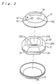
- Fig. 2 is an exploded perspective view of the first embodiment of the radio apparatus according to the present invention.
- Fig. 3(a) is a plan view of the antenna member.
- Fig. 3(b) is a front view of the antenna member.
- Fig. 3(c) is a left side elevational view of the antenna member.
- Fig. 3(d) is a right side elevational view of the antenna member.
- Fig. 4 is an expansion plan view of the antenna member.
- the antenna member 20 (a slot antenna member) is accommodated between the upper casing member 11 and the lower casing member 12.
- the antenna member 20 has a shape which matches the shape of the interior of the upper and lower casing members 11 and 12. That is, the entire shape of the antenna member 20 is hexagonal, as shown in Fig. 3(a), and the antenna member 20 has a side portion 200 which slantingly bulges toward the outer peripheral edge thereof, as shown in Figs. 3(b) to 3(d).
- the antenna member 20 includes a first conductive plate 21 constituting an upper half portion, a second conductive plate 23 which is positioned opposite to the first conductive plate 21 in such a manner that a slot groove is formed between their outer peripheries, and a short-circuiting portion 24 for electrically short-circuiting the first and second conductive plates 21 and 23.
- the first and second conductive plates 21 and 23 have square opening portions 210 and 230 on their surfaces, respectively.
- the first and second conductive plates 21 and 23 and the short-circuiting portion 24 are formed as one unit, as shown in Fig. 4.
- the antenna member 20 shown in Fig. 3 is obtained from the structure shown in Fig. 4 through folding one of the conductive plates back onto the other by bending at a coupling portion 241 between the short-circuiting portion 24 and the first conductive plate 21 and a coupling portion 242 between the short-circuiting portion 24 and the second conductive plate 23.
- the side portion 200 of the antenna member 20 is constituted by side portions 215 and 235 which respectively bulge slantingly toward outer peripheral edges thereof in the first and second conductive plates 21 and 23.
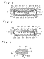
- Fig. 5 is a section taken along the line X-X' of Fig. 1.
- Fig. 6 is a section taken along the line Y-Y' of Fig. 1.
- the antenna member 20 since the antenna member 20 has the bulging side portion 200, it is disposed within the casing 13 along the inner surfaces of the upper and lower casing members 11 and 12, thus substantially eliminating useless space within the side portion 130 of the casing 13.
- the circuit board 30 constituting the radio apparatus circuit is sandwiched between the first and second conductive plates 21 and 23.
- the slot groove 22 of the antenna member 20 is located on the outer peripheral portion of the circuit board 30.
- On the front side of the circuit board 30 is located the opening portion 210 of the first conductive plate 21.
- On the rear side of the circuit board 30 is located the opening portion 230 of the second conductive plate 23.
- the user can replace the button type electric cell 33, serving as a power source of the radio apparatus 10, with a new one through the opening portion 230 by removing a rear lid 125 of the lower casing member 12.
- the short-circuiting portion 24 extends over the slot groove 22 to electrically short-circuit the first and second conductive plates 21 and 23.
- a tuning capacitor element 301 which is electrically connected to both the first and second conductive plates 21 and 23 through terminals 302 and 303, respectively.
- the connecting position of the tuning capacitor element 301 is opposite to the short-circuiting position of the first and second conductive plates 21 and 23 by the short-circuit portion 24, as shown in Fig. 7 which is an equivalent circuit diagram of the antenna member 20.
- the tuning capacitor element 301 enables the antenna member 20 to be tuned at a high antenna gain even if the length of the slot groove 22 is shorter than the length corresponding to half the used wavelength ( ⁇ /2). Thus, locating the tuning capacitor element 301 at a central position in the longitudinal direction of the slot groove 22, i.e., at a position remotest from the short-circuiting portion 24, is the most effective.
- the vicinity of the connecting position of the tuning capacitor element 301 with the antenna member 20 constitutes a high impedance portion of the antenna member 20 from which electromagnetic waves are radiated.
- the radio apparatus 10 when the user carries the radio apparatus 10 around, he or she puts the radio apparatus 10 in a pocket with the connecting position between the tuning capacitor element 301 and the antenna member 20 up or down so as to obtain the highest sensitivity.
- the direction in which the radio apparatus 10 should be directed during use may be indicated by the arrow mark 16 on the upper casing member 11 and/or the cord 74 as mentioned before.
- the radio apparatus circuit is a direct conversion type circuit.
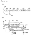
- Fig. 8(a) is a block diagram of such a radio apparatus circuit.
- an RF amplifier 340 (high-frequency amplifying circuit) receiving the signal from the antenna member 20, a mixer 341, a local oscillator 342 (local oscillator circuit), a low-pass filter 343, a detector 344, a decoder 345 and a CPU 346 constitute the radio apparatus circuit.
- a mixer 341 receives the signal from the antenna member 20
- a local oscillator 342 local oscillator circuit
- a low-pass filter 343 a detector 344
- a decoder 345 a CPU 346
- the operation clock of a booster circuit (which will be explained later) is supplied through a power line as noise which is superimposed to the local oscillation signal. If the frequency of the operation clock, which generally ranges from ten plus several kHz to several MHz, is very low and if the C/N ratio of the clock oscillation is not good, the side band noise of the operation clock is supplied from the antenna member 20, passes through the RF circuit and the mixer circuit, and is then converted into base-band noise in the direct conversion detector circuit output, thus reducing the S/N ratio of a received useful signal.
- the antenna member 20 and the local oscillator 342 should be disposed at positions separated from each other.
- a small radio apparatus 10 such as that of this embodiment, it is generally impossible to obtain such a layout.
- the local oscillator 342 is mounted on the front side of the circuit board 30 at a position deviating from the center of the antenna member 20 in the X' direction, i.e., at a position close to the short-circuiting portion 24, in a state wherein it is placed in a shielding box, as shown in Fig. 5, so that the local oscillator 342 can be located at a position where it does not readily influence the antenna member 20. Accordingly, the local oscillator 342 is at a position remote from the connecting position between the tuning capacitor element 301 and the antenna member 20 (which is the highest impedance portion in the antenna member 20) where the antenna member 20 is least influenced by the noise from the local oscillator 342.
- a digital IC 347 functioning as the decoder 345 and the CPU 346, and so on.
- an influence of the digital IC 347 on the antenna member 20 is relatively small, and there is thus no limitation on the position of the digital IC 347.
- mixture of the side band noise into the antenna member 20 can be eliminated when the above-described layout is employed. If the operation clock is set in the stop-band of the low-pass filter and if the clock oscillator is a crystal oscillator, such mixture can be more reliably eliminated.
- Fig. 8(b) is a block diagram of the radio apparatus circuit with power source lines.
- the electric cell 348 is a dry cell or air cell of 1.5 volts or below. A voltage of 2 volts or above is necessary to operate a direct conversion IC 349. Hence, the voltage of the electric cell 348 is boosted by a DC/DC converter 352.
- a voltage boosting method is the charge pumping method by a reactance element.
- a crystal oscillator 350 is used as a reference signal source used to store and discharge electric charges. The crystal oscillator, having a frequency ranging from 32.768 kHz to 76,8 kHz, is also used as a reference signal for clock operation or data demodulation in the CPU.
- the amount of attenuation by the low-pass filter 343 at 32.768 kHz is 90 dB or above. This, together with a high Q of the crystal oscillator 350, can sufficiently attenuate the operation clock and the side band noise.
- the local oscillator 342 is separate, and the mixer 341 is within the IC.
- a signal line 351 is an exposed printed pattern on the board or the like.
- the signal intensity on the signal line 351 at a 50 ⁇ terminal is between -10 dBm and-20 dBm, and the impedance of the signal line 351 is several k ⁇ .
- an externally radiating level is very high, and radiation takes place in upward and downward directions of the signal line 351.
- the local oscillator circuit 342 radiates intense radiations.
- the present inventors measured and found that the radiated electric field level at the input terminal of the RF amplifier 340 is 110 dB ⁇ V.
- the minimum reception electric field level of the radio apparatus 10 is between 10 dB ⁇ V and 15 dB ⁇ V.
- the reception signal wave is distorted and suppressed at either the RF amplifier 340 or the mixer 341 due to disturbance by an electric wave discharged by that radio apparatus and higher by 100 dB than the reception electric field level.
- the level of side band noise occurring in the oscillation signal increases in proportion to the electric field level, and appears as base-band noise, deteriorating the S/N ratio of the reception signal wave.
- This embodiment assures good performance even in a portable radio apparatus having the above-described circuit configuration.
- the radiated electric field level at the input terminal of the RF amplifier 340 reduces to 80 dB ⁇ V.
- the reception signal wave is not suppressed and the side band noise level is reduced, thus increasing the S/N ratio.
- the same effect can be obtained in a structure other than the structure shown in Fig. 8(b) if the local oscillator 342 and the mixer 341 are formed as a shielded single unit so that the output signal of this unit can be a base-band signal and if the low-pass filter 343 and the detector 344 are provided on separate ICs.
- the RF amplifier 340 is connected to both the first and second conductive plates 21 and 23 over the slot groove 22. If the power supply circuit or the reception circuit is an unbalanced circuit, the RF amplifier 340 is connected to either the first conductive plate 21 or the second conductive plate 23.
- the local oscillator 342 which is a noise generation source, is mounted on the front side of the circuit board 30 so that the noise from the local oscillator 342 can be extracted through the opening portion 210 of the first conductive plate 21, and the RF amplifier 340 is connected to the second conductive plate 23 through a connector 304 while a ground potential is applied to the first conductive plate 21 through a connector 305, as shown in Fig. 6, so as to reduce an influence of the noise from the local oscillator 342.
- the connecting position (power supplying point) of the RF amplifier 340 to the second conductive plate 23 is shifted from the connecting position of the tuning capacitor element 301 which indicates the highest impedance in order to simplify impedance matching between the antenna member 20 and the RF amplifier 340.
- the connecting position between the RF amplifier 340 and the antenna member 20 and the position of the local oscillator 342 are shown in Fig. 7.
- the radio apparatus 10 since a slot antenna is used as the antenna member 20, a magnetic field component is detected. Further, the radio apparatus 10 is suitable for use as a pager, because the antenna gain increases due to the image effect of a human body when the radio apparatus 10 is placed in a chest pocket.
- the side portion 200 of the antenna member 20 slantingly bulges toward an outer periphery thereof so that it matches the shape of the side portion 130 of the casing 13 which curvedly bulges toward an outer periphery thereof.
- the antenna member 20 can be packed in the casing 13 along the inner surface of the side portion 130 of the casing 13, eliminating useless space within the casing 13. Consequently, a relatively small size of the radio apparatus 10 can be achieved while a high degree of freedom is assured in the design of the radio apparatus 10.
- the antenna member 20 has the opening portions 210 and 230, the noise generated from the circuit board 30 escapes from the opening portions 210 and 230, that is, the noise does not readily supply the antenna member 20. It is possible to dispose the liquid crystal display panel 14 utilizing the opening portion 210. Further, in this embodiment, since the local oscillator 342 is disposed near a low impedance position on the antenna member 20, the noise generated from the local oscillator 342 does not readily supply the antenna member 20. Thus, in a direct conversion type radio apparatus 10, even if the local oscillator 342 is disposed near the antenna member 20, an influence of the noise generated by the local oscillator 342 can be reduced. As a result, the relatively small size can be achieved while a high sensitivity is maintained.
- a dielectric material glass-epoxy resin
- a reception signal is apparently shortened in proportion to the square root of a dielectric constant of the dielectric material filled in the slot groove 22. This is equivalent to the effective length of the antenna member 20 being extended.
- the antenna member 20 the radio apparatus 10) can be made even smaller and thinner.
- the local oscillator 342 which is the major noise generation source
- the local oscillator 342 is shown to be disposed at a position deviating from the central portion of the antenna member 20 toward the short-circuiting portion 24 in order to suppress an influence from the electronic parts mounted on the circuit board 30, it is desirable that other noise generation sources be also disposed at positions deviating toward the short-circuiting portion 24.
- the circuit board 30 itself may be disposed at a position deviating from the central portion of the antenna member 20 toward the short-circuiting portion 24.
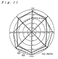
- a bearing characteristic 101 indicates the reception sensitivity of a portable radio apparatus in free space (not influenced by a human body etc.) which employs a slot antenna shown in Fig. 7 in which the conductive plates 21 and 23 are formed vertically
- a bearing characteristic 100 indicates the reception sensitivity of a portable radio apparatus in free space which employs the antenna member 20 according to the present embodiment in which the conductive plates 21 and 23 form the side portion 200, a shown in Fig. 2(b).
- the entire length of the antenna member 20 is 150 mm
- the reception frequency is 280 MHz.
- the best value is 14 dB ⁇ V/m, which is better by 3 dB to 4 dB than the best value of the bearing characteristic 101.
- the opening area must be correspondingly large, thus precluding a small size of the radio apparatus.
- a previously useless space S shown in Fig. 21 can be utilized effectively, excellent characteristics can be obtained while a reduction in the size can be achieved.
- a bearing characteristic 100 indicates the reception sensitivity of a portable radio apparatus according to the present invention in free space, in which the local oscillator 342 is disposed at a position deviating from the center of the antenna member 20 in the X' direction, as shown in Fig. 5, and a bearing characteristic 102 indicates the reception sensitivity of a portable radio apparatus in free space, in which the local oscillator 342 deviates in the opposite direction to the X' direction.
- the difference between the bearing characteristics 100 and 102 is about 10 dB. This indicates that the reception sensitivity is affected by the layout. In a slot antenna, the vicinity of the short-circuiting portion 24 has the lowest impedance. Thus, even if noise is radiated from the local oscillator 342 from that vicinity, the level of noise which supplies the antenna member 20 is small.
- bearing characteristics 103 and 100 indicate the reception sensitivity of a radio apparatus 10 in which the antenna member 20 is put on a human body and not put on a human body, respectively. How the radio apparatus 10 is put on the human body is illustrated in Fig. 1(d). When the portable radio apparatus is put on the front of a human body, the sensitivity is improved by about 4 dB. This indicates that the antenna member 20 according to this embodiment detected the magnetic field component, like a loop antenna.
- a bearing characteristic 103 indicates the reception sensitivity of the radio apparatus 10 according to the present embodiment which employs the antenna member 20, when the radio apparatus 10 is put on a human body
- a bearing characteristic 104 indicates the reception sensitivity of a conventional super-heterodyne type portable radio apparatus which employs a loop antenna, when the radio apparatus is put on a human body.
- the reception sensitivity was almost the same, namely 10 dB ⁇ V/m.
- the frequency of a local oscillation signal differs from the reception frequency by, for example, 455 kHz or 10 MHz.
- a radio apparatus can be designed in the manner shown in Fig. 1, and characteristics equivalent to those of a conventional super-heterodyne type radio apparatus can be obtained.
- a second embodiment is constructed such that a side portion 400 of an antenna member 40 (slot antenna member) curvedly bulges toward an outer periphery thereof in the same manner as the casing 13 having the same shape as that of the first embodiment, as shown in Fig. 13.
- the side portion 400 of the antenna member 40 is closely attached to the inner surface of the side portion 130 of the casing 13, as shown in Figs. 14 and 15, and thus there is substantially no space between the antenna member 40 and the casing 13.
- the antenna member 40 includes first and second conductive plates 41 and 43 which sandwich the circuit board 30 and constitute a slot groove 42 outside the periphery of the circuit board 30, and a short-circuiting portion 44 for electrically short-circuiting the first and second conductive plates 41 and 43.
- the side portion 400 of the antenna member 40 is constituted by side portions 415 and 435 of the first and second conductive plates 41 and 43 which curvedly bulge toward outer peripheral edges thereof.
- the first and second conductive plates 41 and 43 have opening portions 410 and 430, respectively, at positions corresponding to the two sides of the circuit board 30.
- the other structure of this embodiment is the same as that of the first embodiment, the description thereof being, therefore, omitted.
- the radio apparatus 10a arranged in the manner described above has the same effects as those of the first embodiment. That is, since the antenna member 20 is a slot antenna, the magnetic field component is detected. Further, when the radio apparatus 10a is put in a chest pocket, the antenna gain is increased due to the image effect of the human body.
- the side portion 400 of the antenna member 40 curvedly bulges toward an outer periphery thereof so that it matches the shape of the side portion 130 of the casing 13 which curvedly bulges toward an outer periphery thereof, there is no useless space on the inner side of the side portion 130 of the casing 13.
- a high degree of freedom can be obtained in designing of the radio apparatus 10, while a reduction in the size thereof can be achieved.
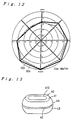
- Fig. 17 is a perspective view illustrating the external shape of a portable radio apparatus according to a third embodiment.
- Fig. 18(a) is a development view of an antenna member employed in the third embodiment.
- Fig. 18(b) is a perspective view of the antenna member.
- Fig. 18(c) is a bottom plan view of the antenna member.
- Fig. 18(d) is a side elevational view of the antenna member.
- a casing 53 has a substantially spherical shape, and a liquid crystal display panel 54 with a protective lens is disposed at a position corresponding to a pole of that spherical shape. Operation buttons 551 and 552 are disposed at the side of the liquid crystal display panel 54.
- the arrow mark 56 is provided on the casing 53 to indicate that the radio apparatus 50 should be put in a pocket and carried around with this side up (a cord like cord 74 of Fig. 1 may be used instead or in addition).
- the sensitivity of the radio apparatus 50 becomes maximum.
- such a spherical radio apparatus 50 accommodates an antenna member (slot antenna member) 60 formed by superimposing substantially semi-spherical first and second conductive plates 61 and 63 one on top of the other in such a manner that a slot groove 62 is provided therebetween.
- the first conductive plate 61 is electrically short-circuited to the second conductive plate 63 through the short-circuiting portion 64.
- the tuning capacitor element 301 is connected to both the first and second conductive plates 61 and 63 at a position opposite to that where the short-circuiting portion 64 is provided.
- the first conductive plate 61 has an opening portion 610 at a portion thereof corresponding to one pole of the spherical form.
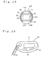
- Fig. 19 is a vertical cross-sectional view of the radio apparatus 50.
- the liquid crystal display panel 14 with the protective lens 140 is disposed at the opening portion 610 of the first conductive plate 61.
- An opening portion 630 is formed at a portion of the second conductive plate 63 corresponding to the other pole so that the user can replace the electric cell 33 with a new one through the opening portion 630 by opening a rear lid 525.
- the circuit board 30 is disposed within the antenna member 60 as a circuit block.
- the radio apparatus circuit constituted by the circuit board 30 is the direct conversion type, the local oscillator is disposed in the same manner as in the previous embodiments at a position deviating from the central portion of the antenna member 60 toward the short-circuiting portion 64 so that the noise generated by the local oscillator does not supply the antenna member 60.
- the circuit board 30 itself may be disposed at a position deviating from the center of the antenna member 60 toward the short-circuiting portion 64.
- the other structure of this embodiment is the same as that of the first embodiment.
- the radio apparatus 50 arranged in the manner described above has the same effects as those of the previous embodiments. That is, since the antenna member 60 is a slot antenna, the magnetic field component is detected. Further, when carried around in a chest pocket, the antenna gain is increased due to the image effect of the human body.
- the spherical antenna member 60 is formed by semi-spherical first and second conductive plates 61 and 63 so that it matches the spherical shape of the casing 53, and such an antenna member 60 is accommodated in the casing 53. Accordingly, there is no useless space within the casing 53, and consequently, a high degree of freedom can be obtained in designing the radio apparatus 50, and a reduction in the size thereof can be achieved.
- Fig. 20 illustrates a portable radio apparatus 70 as a modification of the first and second embodiments.
- the radio apparatus 70 has shape in which a recessed portion 71 is formed at one side thereof while a bulging portion 72 is formed on the other side. This facilitates the user's holding of the radio apparatus 70.
- a side portion 73 bulges toward an outer periphery thereof, and a slot antenna member, such as that employed in the first or second embodiment in which the side portion thereof bulges toward an outer periphery thereof, is used, although not shown, so as to achieve reduction in the entire size of the radio apparatus 70.
- Such a radio apparatus 70 has advantages in that it has a good design and in that it allows the user to feel with hands the direction in which the radio apparatus 70 is directed in a pocket. Further, when the radio apparatus 70 is hung using a curled cord 74, as shown in Fig. 1(d), the antenna gain can be increased. Further, the radio apparatus 70 enables the user to carry it handily as if the user is wearing an
- the casing has the side portion which bulges toward an outer periphery thereof, and the first and second conductive plates, constituting the slot antenna member, have the side portions which bulge toward outer peripheral edges thereof and form the slot groove therein.
- the casing has a substantially spherical form, and the first and second conductive plates, constituting the slot antenna member accommodated in the casing, have a substantially semi-spherical external shape.
- the first and second conductive plates have an opening portion at an area which faces the circuit board.
- the circuit board which is the noise generating source, or the local oscillator mounted on the circuit board is disposed at a position deviating from the central portion of the antenna member toward the short-circuiting portion, the noise generation source can be separated from the high impedance portion of the antenna member.
- a noise signal does not readily supply the antenna member, even if the direct conversion method is employed, transmission or reception of the portable radio apparatus and other radio apparatuses is not interfered.
- the high-frequency amplifying circuit of the radio apparatus circuit is preferably electrically connected to the conductive plate located on the side of the circuit board which is opposite to the side thereof where the local oscillator circuit of the radio apparatus circuit is provided, to reduce an influence of the noise from the local oscillator circuit.
- a dielectric material may be filled in the slot groove, whereby the reception wavelength is apparently shortened, enabling a small antenna to receive signals of long wavelengths.
Landscapes
- Support Of Aerials (AREA)
- Waveguide Aerials (AREA)
- Transceivers (AREA)
Claims (16)
- Tragbares Funkgerät, umfassend:dadurch gekennzeichnet, daß zumindest ein Seitenabschnitt (130) des Gehäuses eine abgerundete Form aufweist und die erste und die zweite leitfähige Platte so ausgebildet sind, daß sie im wesentlichen zur abgerundeten Form des Gehäuses passen.eine Leiterplatte (30), die eine Funkgeräteschaltung bildet,ein Spaltantennenelement (20; 40; 60), das eine erste und eine zweite leitfähige Platte (21, 23; 41, 43; 61, 63) umfaßt, die so angeordnet sind, daß sich die Leiterplatte zwischen ihnen befindet und daß sie eine Spaltnut (22; 42; 62) an einem Außenrandabschnitt der Leiterplatte begrenzen, wobei die leitfähigen Platten durch einen Kurzschließabschnitt (24; 44; 64) über die Spaltnut hinweg kurzgeschlossen sind, undein Gehäuse (13; 53), in dem die Leiterplatte und das Spaltantennenelement untergebracht sind,
- Gerät nach Anspruch 1, bei dem das Gehäuse (13) einen Seitenabschnitt (130) aufweist, der zu dessen Außenrand hin ausgebaucht ist, und die erste und die zweite leitfähige Platte (21, 23; 41, 43) Seitenabschnitte (200; 400) aufweisen, die so ausgebaucht sind, daß der Abstand zwischen den leitfähigen Platten zu deren Außenrandkanten hin abnimmt, wobei die erste und die zweite leitfähige Platte so angeordnet sind, daß sich die Leiterplatte (30) in Zwischenlage zwischen ihnen befindet.
- Gerät nach Anspruch 2, bei dem die Seitenabschnitte (200) der ersten und der zweiten leitfähigen Platte (21, 23) zu deren Außenrandkanten hin schräg ausgebaucht sind.
- Gerät nach Anspruch 2, bei dem die Seitenabschnitte (400) der ersten und der zweiten leitfähigen Platte (41, 43) zu deren Außenrandkanten hin gekrümmt ausgebaucht sind.
- Gerät nach Anspruch 1, bei dem das Gehäuse (53) eine im wesentlichen kugelförmige äußere Form aufweist und die erste und die zweite leitfähige Platte (61, 63) jeweils eine im wesentlichen halbkugelige äußere Form aufweisen, wobei die erste und die zweite leitfähige Platte so angeordnet sind, daß die Leiterplatte (30) in ihnen untergebracht ist.
- Gerät nach einem der vorhergehenden Ansprüche, ferner umfassend ein Abstimmkondensatorelement (301), das an die erste und die zweite leitfähige Platte (21, 23; 41, 43; 61, 63) an einer Position elektrisch angeschlossen ist, die einer Position gegenüberliegt, bei der der Kurzschließabschnitt (24; 44; 64) gebildet ist.
- Gerät nach einem der vorhergehenden Ansprüche, bei dem die erste und die zweite leitfähige Platte (21, 23; 41; 43; 61, 63) jeweils einen Öffnungsabschnitt (210, 230; 610, 630) in einem der Leiterplatte (30) gegenüberliegenden Bereich aufweisen.
- Gerät nach einem der vorhergehenden Ansprüche, bei dem die Leiterplatte (30) in einer Position angeordnet ist, die von einem Mittelabschnitt der Spaltantenne (20; 40; 60) zu dem Kurzschließabschnitt (24; 44; 64) hin versetzt ist.
- Gerät nach einem der vorhergehenden Ansprüche, bei dem die Funkgeräteschaltung eine Direktumwandlungsschaltung ist, wobei sich eine Überlagerungsoszillatorschaltung (342) von ihr in einer Position befindet, die von einem Mittelabschnitt des Antennenelements (20; 40; 60) zu dem Kurzschließabschnitt (24; 44; 64) hin versetzt ist.
- Gerät nach einem der vorhergehenden Ansprüche, bei dem die Funkgeräteschaltung eine Direktumwandlungsschaltung ist, wobei eine Hochfrequenzverstärkungsschaltung (340) von ihr an diejenige der leitfähigen Platten (21, 23; 41, 43; 61, 63) elektrisch angeschlossen ist, die sich auf einer Seite der Leiterplatte (30) befindet, die von deren Seite abgewandt ist, wo eine Überlagerungsoszillatorschaltung (342) der Funkgeräteschaltung vorgesehen ist.
- Gerät nach Anspruch 9 oder 10, bei dem die Direktumwandlungsfunkgeräteschaltung, eine Orthogonaltransformationsmischerschaltung und eine Basisbandsignalerfassungsschaltung im gleichen IC angeordnet sind.
- Gerät nach Anspruch 9, 10 oder 11, bei dem die Direktumwandlungsfunkgeräteschaltung über eine Spannungserhöhungsschaltung (352) zum Erhöhen der Spannung einer elektrischen Zelle getrieben wird, wobei die Betriebsfrequenz der Spannungserhöhungsschaltung auf einen Sperrbereich einer in der Funkgeräteschaltung enthaltenen Basisbandsignalfilterschaltung (343) eingestellt ist.
- Gerät nach Anspruch 12, bei dem die Betriebsfrequenz durch einen Kristalloszillator (350) eingestellt ist.
- Gerät nach einem der vorhergehenden Ansprüche, bei dem die Spaltnut (22; 42; 62) mit einem dielektrischen Stoff gefüllt ist.
- Gerät nach einem der vorhergehenden Ansprüche in Kombination mit Anspruch 6, ferner umfassend eine Anzeigeanordnung (16, 74), die an der Außenseite des Gehäuses (13; 53) in einer Position entsprechend der Position entweder der Verbindungsposition zwischen der ersten und der zweiten leitfähigen Platte (21, 23; 41, 43; 61, 63) durch das Abstimmkondensatorelement (301) oder des Kurzschließabschnitts (24; 44; 64) vorgesehen ist.
- Gerät nach Anspruch 15, bei dem die Anzeigeanordnung ein Spiralkabel (74) umfaßt, das in der genannten Position an dem Gehäuse befestigt ist.
Applications Claiming Priority (3)
| Application Number | Priority Date | Filing Date | Title |
|---|---|---|---|
| JP24022794 | 1994-10-04 | ||
| JP240227/94 | 1994-10-04 | ||
| JP24022794A JP3417083B2 (ja) | 1994-10-04 | 1994-10-04 | 携帯用無線機 |
Publications (3)
| Publication Number | Publication Date |
|---|---|
| EP0706232A2 EP0706232A2 (de) | 1996-04-10 |
| EP0706232A3 EP0706232A3 (de) | 1997-01-22 |
| EP0706232B1 true EP0706232B1 (de) | 2002-01-02 |
Family
ID=17056347
Family Applications (1)
| Application Number | Title | Priority Date | Filing Date |
|---|---|---|---|
| EP95115659A Expired - Lifetime EP0706232B1 (de) | 1994-10-04 | 1995-10-04 | Tragbares Funkgerät |
Country Status (6)
| Country | Link |
|---|---|
| US (1) | US5946610A (de) |
| EP (1) | EP0706232B1 (de) |
| JP (1) | JP3417083B2 (de) |
| KR (1) | KR100349524B1 (de) |
| CN (1) | CN1082281C (de) |
| DE (1) | DE69524834T2 (de) |
Families Citing this family (43)
| Publication number | Priority date | Publication date | Assignee | Title |
|---|---|---|---|---|
| JP3603995B2 (ja) | 1999-03-31 | 2004-12-22 | シャープ株式会社 | 高周波無線通信装置 |
| US6483473B1 (en) | 2000-07-18 | 2002-11-19 | Marconi Communications Inc. | Wireless communication device and method |
| US6806842B2 (en) | 2000-07-18 | 2004-10-19 | Marconi Intellectual Property (Us) Inc. | Wireless communication device and method for discs |
| US7098850B2 (en) | 2000-07-18 | 2006-08-29 | King Patrick F | Grounded antenna for a wireless communication device and method |
| USD456383S1 (en) | 2001-05-24 | 2002-04-30 | Unitime International Co., Ltd. | FM radio |
| ATE541246T1 (de) * | 2001-06-29 | 2012-01-15 | Maruman Products Co Ltd | Funkarmbanduhr |
| JP2003209419A (ja) | 2002-01-16 | 2003-07-25 | Toshiba Corp | 電子機器及びアンテナ実装方法 |
| EP1420476B1 (de) * | 2002-11-13 | 2008-02-06 | Mitsubishi Materials Corporation | Armbanduhr mit internem Transponder, Funkuhr und Antenne für Armbanduhr |
| USD492279S1 (en) | 2003-07-09 | 2004-06-29 | Oneworld Enterprises Ltd. | Radio |
| USD519981S1 (en) * | 2004-07-29 | 2006-05-02 | Kings Manufacturing Company, Ltd. | Radio |
| US7577405B1 (en) * | 2005-07-15 | 2009-08-18 | The United States Of America As Represented By The Secretary Of The Navy | Disposable radio communication device |
| US8175547B1 (en) * | 2005-07-15 | 2012-05-08 | The United States Of America As Represented By The Secretary Of The Navy | Disposable chemical sensor and wireless communication device |
| FI124133B (fi) * | 2005-10-21 | 2014-03-31 | Suunto Oy | Elektroninen puettava laite |
| US7215600B1 (en) * | 2006-09-12 | 2007-05-08 | Timex Group B.V. | Antenna arrangement for an electronic device and an electronic device including same |
| USD606970S1 (en) * | 2007-10-18 | 2009-12-29 | Able Planet, Incorporated | Head set |
| USD606969S1 (en) * | 2007-10-18 | 2009-12-29 | Able Planet, Incorporated | Head set |
| USD626963S1 (en) * | 2008-04-22 | 2010-11-09 | Samsung Techwin Co., Ltd. | Integrated RFID reader |
| US20090289855A1 (en) * | 2008-05-23 | 2009-11-26 | Sony Ericsson Mobile Communications Ab | Methods and Apparatus for Providing an Integrated Inverted Loop Antenna in a Wireless Device |
| USD598003S1 (en) * | 2008-11-24 | 2009-08-11 | Motorola, Inc. | Speakerphone device |
| CN101938541A (zh) * | 2010-09-17 | 2011-01-05 | 鸿富锦精密工业(深圳)有限公司 | 具有无线通讯功能的腕戴式电子装置 |
| USD697510S1 (en) * | 2011-03-23 | 2014-01-14 | Brother Industries, Ltd. | Scanner with projector |
| US11059550B2 (en) | 2013-03-11 | 2021-07-13 | Suunto Oy | Diving computer with coupled antenna and water contact assembly |
| US10734731B2 (en) | 2013-03-11 | 2020-08-04 | Suunto Oy | Antenna assembly for customizable devices |
| US10594025B2 (en) | 2013-03-11 | 2020-03-17 | Suunto Oy | Coupled antenna structure and methods |
| US11050142B2 (en) | 2013-03-11 | 2021-06-29 | Suunto Oy | Coupled antenna structure |
| GB2570904B (en) * | 2018-02-08 | 2021-10-27 | Suunto Oy | Slot mode antennas |
| TWI580107B (zh) * | 2016-01-25 | 2017-04-21 | 廣達電腦股份有限公司 | 穿戴式裝置 |
| CN105976591B (zh) * | 2016-06-23 | 2019-03-15 | 国网山东省电力公司日照供电公司 | 基于等电位环原理的高压输电线路无线通讯装置 |
| USD834565S1 (en) * | 2016-11-10 | 2018-11-27 | Crestron Electronics, Inc. | Conference microphone |
| TWI790344B (zh) | 2018-02-08 | 2023-01-21 | 芬蘭商順妥公司 | 槽孔模式天線 |
| TWI798344B (zh) | 2018-02-08 | 2023-04-11 | 芬蘭商順妥公司 | 槽孔模式天線 |
| US11296731B2 (en) | 2018-03-07 | 2022-04-05 | Phc Holdings Corporation | Communication device |
| US10539700B1 (en) | 2019-03-14 | 2020-01-21 | Suunto Oy | Diving computer with coupled antenna and water contact assembly |
| CA3200775A1 (en) | 2019-04-26 | 2020-10-29 | Batelle Memorial Institute | Systems and methods for signal communication with scalable, modular network nodes |
| CN111029747A (zh) * | 2019-12-25 | 2020-04-17 | 惠州Tcl移动通信有限公司 | 电子设备 |
| USD1113875S1 (en) | 2020-04-24 | 2026-02-17 | Battelle Memorial Institute | Interface board for radio frequency antenna |
| USD991250S1 (en) | 2021-09-14 | 2023-07-04 | Hewlett-Packard Development Company, L.P. | Conference device |
| USD997902S1 (en) | 2021-09-14 | 2023-09-05 | Hewlett-Packard Development Company, L.P. | Speaker |
| USD986308S1 (en) | 2021-09-14 | 2023-05-16 | Hewlett-Packard Development Company, L.P. | Camera |
| USD989047S1 (en) * | 2021-09-14 | 2023-06-13 | Hewlett-Packard Development Company, L.P. | Microphone |
| USD1017588S1 (en) * | 2022-05-04 | 2024-03-12 | Solid State Logic Uk Limited | Microphone |
| US11901930B1 (en) | 2023-04-26 | 2024-02-13 | Battelle Memorial Institute | Radio frequency aperture with cooling assembly |
| USD1099884S1 (en) | 2023-11-17 | 2025-10-28 | Battelle Memorial Institute | Array box |
Family Cites Families (84)
| Publication number | Priority date | Publication date | Assignee | Title |
|---|---|---|---|---|
| US2070088A (en) * | 1934-05-17 | 1937-02-09 | Montaruli Antonio | Radio cabinet |
| BE472157A (de) * | 1945-08-13 | |||
| NL71623C (de) * | 1945-08-25 | |||
| BE472929A (de) * | 1946-01-12 | |||
| US2611865A (en) * | 1946-06-19 | 1952-09-23 | Alford Andrew | Transversely gapped cylindrical antenna |
| DE1090140B (de) * | 1957-06-26 | 1960-09-29 | Autophon Ag | Tragbarer, eine Antenne umfassender Rufempfaenger fuer Personensuchanlagen |
| CH379586A (de) * | 1960-05-23 | 1964-07-15 | Patelhold Patentverwertung | Hochfrequenzsender |
| US3172112A (en) * | 1961-05-29 | 1965-03-02 | Elwin W Seeley | Dumbbell-loaded folded slot antenna |
| US3210766A (en) * | 1962-02-15 | 1965-10-05 | Ralph O Parker | Slot type antenna with tuning circuit |
| JPS5441192B2 (de) * | 1973-08-01 | 1979-12-07 | ||
| US4035807A (en) * | 1974-12-23 | 1977-07-12 | Hughes Aircraft Company | Integrated microwave phase shifter and radiator module |
| JPS5512762A (en) * | 1978-07-14 | 1980-01-29 | Toshiba Corp | Glass sealing type semiconductor device manufacturing method |
| JPS5627514A (en) * | 1979-08-13 | 1981-03-17 | Pioneer Electronic Corp | Tuning circuit of balanced antenna |
| JPS56169401A (en) * | 1980-05-31 | 1981-12-26 | Shuichi Sakai | Antenna for wrist watch type receiver |
| US4419770A (en) * | 1981-05-02 | 1983-12-06 | Sony Corporation | Wrist AM radio receiver |
| JPS5894204A (ja) * | 1981-11-30 | 1983-06-04 | Seiko Instr & Electronics Ltd | 磁心入りル−プアンテナ |
| JPS5910049A (ja) | 1982-07-07 | 1984-01-19 | Fujitsu Ltd | クロツク再生方式 |
| US4509053A (en) * | 1982-07-26 | 1985-04-02 | Sensor Systems, Inc. | Blade antenna with shaped dielectric |
| JPS5944103A (ja) * | 1982-09-07 | 1984-03-12 | Toshiba Corp | アンテナ装置 |
| EP0122485B1 (de) * | 1983-03-19 | 1987-09-02 | Nec Corporation | Zweifach-Schleifenantenne |
| JPS607204A (ja) * | 1983-06-27 | 1985-01-16 | Toyo Commun Equip Co Ltd | 小型無線機のアンテナ |
| JPS60239106A (ja) * | 1984-05-14 | 1985-11-28 | Matsushita Electric Ind Co Ltd | スロツトアンテナ |
| JPS6126307A (ja) * | 1984-07-17 | 1986-02-05 | Yagi Antenna Co Ltd | アンテナ装置 |
| JPS6150542A (ja) * | 1984-08-18 | 1986-03-12 | 松下電器産業株式会社 | 電気掃除機 |
| GB2165396B (en) * | 1984-10-09 | 1987-12-23 | Standard Telephones Cables Plc | Buoyant antenna |
| US4713808A (en) * | 1985-11-27 | 1987-12-15 | A T & E Corporation | Watch pager system and communication protocol |
| JPS61150410A (ja) * | 1984-12-24 | 1986-07-09 | Sony Corp | チユ−ナ装置 |
| JPS61200702A (ja) * | 1985-03-04 | 1986-09-05 | Nippon Telegr & Teleph Corp <Ntt> | アンテナ切替形携帯無線機 |
| JPH0682974B2 (ja) * | 1985-04-17 | 1994-10-19 | 日本電装株式会社 | 携帯型受信アンテナ装置 |
| JPH0685487B2 (ja) * | 1985-05-18 | 1994-10-26 | 日本電装株式会社 | 2周波共用平面アンテナ |
| JPS6224705A (ja) * | 1985-07-25 | 1987-02-02 | Matsushita Electric Works Ltd | アンテナ |
| US4736390A (en) * | 1986-10-15 | 1988-04-05 | Itt Avionics, A Division Of Itt Corporation | Zero IF radio receiver apparatus |
| US4862181A (en) * | 1986-10-31 | 1989-08-29 | Motorola, Inc. | Miniature integral antenna-radio apparatus |
| GB2201266A (en) * | 1986-12-23 | 1988-08-24 | Upperpace Limited | A radio paging watch |
| JPH0727020B2 (ja) * | 1986-12-25 | 1995-03-29 | 三菱電機株式会社 | レ−ダ−装置 |
| EP0341238B1 (de) * | 1987-01-02 | 1993-12-08 | Motorola, Inc. | System zur automatischen abstimmung einer antenne für tragbare kommunikationsanlagen |
| EP0341239B1 (de) * | 1987-01-02 | 1993-04-28 | Motorola, Inc. | Gerät zur abstimmung einer antenne für personenkommunikationsanlagen |
| SE460704B (sv) * | 1987-06-24 | 1989-11-13 | Bjarne Nilsson | Filterpaase |
| JP2624257B2 (ja) * | 1987-06-29 | 1997-06-25 | 日本電気株式会社 | 無線機用アンテナ |
| US5007105A (en) * | 1987-08-14 | 1991-04-09 | Nec Corporation | Watch type paging receiver |
| US4873527A (en) * | 1988-01-07 | 1989-10-10 | Motorola, Inc. | Antenna system for a wrist carried paging receiver |
| GB8803871D0 (en) * | 1988-02-19 | 1988-03-23 | Woodville Polymer Eng | Trihedral reflectors |
| JP2806525B2 (ja) * | 1988-03-04 | 1998-09-30 | 日本電気株式会社 | 表示機能付受信機 |
| US5265265A (en) * | 1990-02-09 | 1993-11-23 | Seiko Epson Corporation | Wristwatch radio communication device having an improved noise shielding structure |
| US5280646A (en) * | 1988-03-23 | 1994-01-18 | Seiko Epson Corporation | Paging device with structure for removing static electricity |
| JPH01241927A (ja) * | 1988-03-24 | 1989-09-26 | Kokusai Electric Co Ltd | 無線呼出用受信機 |
| JPH01245721A (ja) * | 1988-03-28 | 1989-09-29 | Matsushita Electric Works Ltd | 無線装置 |
| JPH01246904A (ja) * | 1988-03-28 | 1989-10-02 | Kokusai Electric Co Ltd | 小形アンテナ |
| CH672870B5 (de) * | 1988-04-26 | 1990-07-13 | Ebauchesfabrik Eta Ag | |
| US5227804A (en) * | 1988-07-05 | 1993-07-13 | Nec Corporation | Antenna structure used in portable radio device |
| JP2830095B2 (ja) * | 1988-08-05 | 1998-12-02 | セイコーエプソン株式会社 | アンテナ回路及び腕装着型無線機 |
| KR920002439B1 (ko) * | 1988-08-31 | 1992-03-24 | 삼성전자 주식회사 | 휴대용 무선전화기의 슬로트 안테나 장치 |
| JPH02116228A (ja) * | 1988-10-26 | 1990-04-27 | Nec Corp | 携帯用無線機 |
| JPH02126702A (ja) * | 1988-11-07 | 1990-05-15 | Kokusai Electric Co Ltd | 携帯用無線受信機 |
| US5136719A (en) * | 1988-12-05 | 1992-08-04 | Seiko Corp. | Automatic antenna tubing method and apparatus |
| US5113196A (en) * | 1989-01-13 | 1992-05-12 | Motorola, Inc. | Loop antenna with transmission line feed |
| GB2229319B (en) * | 1989-01-20 | 1993-10-20 | Antenna Products Ltd | Antenna |
| US5128686A (en) * | 1989-01-23 | 1992-07-07 | Motorola, Inc. | Reactance buffered loop antenna and method for making the same |
| DE4090272C2 (de) * | 1989-02-23 | 1995-02-23 | Fujitsu Ltd | Schnurloses Freisprech-Telefon |
| US4980694A (en) * | 1989-04-14 | 1990-12-25 | Goldstar Products Company, Limited | Portable communication apparatus with folded-slot edge-congruent antenna |
| US5231407A (en) * | 1989-04-18 | 1993-07-27 | Novatel Communications, Ltd. | Duplexing antenna for portable radio transceiver |
| US4973944A (en) * | 1989-05-19 | 1990-11-27 | Maletta Gabriel J | Electrical signal and alarm protection proximity device |
| US5048118A (en) * | 1989-07-10 | 1991-09-10 | Motorola, Inc. | Combination dual loop antenna and bezel with detachable lens cap |
| AT393054B (de) * | 1989-07-27 | 1991-08-12 | Siemens Ag Oesterreich | Sende- und/oder empfangsanordnung fuer tragbare geraete |
| JPH073924B2 (ja) * | 1989-10-09 | 1995-01-18 | 公人 堀江 | バンド型アンテナ装置 |
| US4977614A (en) * | 1989-10-23 | 1990-12-11 | Motorola, Inc. | Wristband with loop antenna |
| JPH03147406A (ja) * | 1989-11-02 | 1991-06-24 | Nippon Telegr & Teleph Corp <Ntt> | 小形アンテナ |
| JPH03181208A (ja) * | 1989-12-08 | 1991-08-07 | Matsushita Electric Ind Co Ltd | 小形アンテナ |
| JPH03228407A (ja) * | 1989-12-11 | 1991-10-09 | Nec Corp | アンテナおよび該アンテナを用いた携帯用無線機 |
| JP3055703B2 (ja) * | 1990-02-20 | 2000-06-26 | 日本電信電話株式会社 | 腕時計形受信機 |
| US5179733A (en) * | 1990-04-23 | 1993-01-12 | Seiko Epson Corporation | Wristwatch band with radio antenna |
| US5134724A (en) * | 1990-05-08 | 1992-07-28 | Seiko Corp. | Wrist band for wrist-mounted radio with an uninsulated buckle |
| US5182568A (en) * | 1990-05-21 | 1993-01-26 | Motorola, Inc. | Loss cancellation element for an integral antenna receiver |
| US5134418A (en) * | 1990-06-04 | 1992-07-28 | Motorola, Inc. | Apparatus for sensing the integrity of a wristband antenna |
| FR2677814B1 (fr) * | 1990-06-22 | 1993-10-29 | Thomson Csf | Antenne plate hyperfrequence a deux polarisations orthogonales avec un couple de fentes orthogonales rayonnantes. |
| WO1992002970A1 (en) * | 1990-07-27 | 1992-02-20 | Motorola, Inc. | Insulated clasp for a wrist band loop antenna |
| GB9021292D0 (en) * | 1990-10-01 | 1990-11-14 | Watt Mervyn R | Ladder scaffolding |
| WO1992020117A1 (fr) * | 1991-05-09 | 1992-11-12 | Seiko Epson Corporation | Antenne et petit appareil radio portatif |
| US5144325A (en) * | 1991-08-02 | 1992-09-01 | Motorola, Inc. | Detachable wrist band antenna |
| KR930703716A (ko) * | 1991-11-05 | 1993-11-30 | 스스무 아이자와 | 무선기용 안테나 장치 |
| US5589840A (en) * | 1991-11-05 | 1996-12-31 | Seiko Epson Corporation | Wrist-type wireless instrument and antenna apparatus |
| US5280296A (en) * | 1992-04-29 | 1994-01-18 | Motorola, Inc. | Antenna system for a wrist carried selective call receiver |
| GB2276274B (en) * | 1993-03-17 | 1997-10-22 | Seiko Epson Corp | Slot antenna device |
| GB9410557D0 (en) * | 1994-05-26 | 1994-07-13 | Schlumberger Ind Ltd | Radio antennae |
-
1994
- 1994-10-04 JP JP24022794A patent/JP3417083B2/ja not_active Expired - Fee Related
-
1995
- 1995-09-25 KR KR1019950031560A patent/KR100349524B1/ko not_active Expired - Fee Related
- 1995-10-03 US US08/538,788 patent/US5946610A/en not_active Expired - Lifetime
- 1995-10-04 CN CN95117229A patent/CN1082281C/zh not_active Expired - Fee Related
- 1995-10-04 DE DE69524834T patent/DE69524834T2/de not_active Expired - Lifetime
- 1995-10-04 EP EP95115659A patent/EP0706232B1/de not_active Expired - Lifetime
Also Published As
| Publication number | Publication date |
|---|---|
| DE69524834D1 (de) | 2002-02-07 |
| EP0706232A2 (de) | 1996-04-10 |
| CN1128441A (zh) | 1996-08-07 |
| KR100349524B1 (ko) | 2003-02-19 |
| DE69524834T2 (de) | 2002-06-27 |
| JPH08107308A (ja) | 1996-04-23 |
| EP0706232A3 (de) | 1997-01-22 |
| JP3417083B2 (ja) | 2003-06-16 |
| US5946610A (en) | 1999-08-31 |
| CN1082281C (zh) | 2002-04-03 |
| KR960016006A (ko) | 1996-05-22 |
Similar Documents
| Publication | Publication Date | Title |
|---|---|---|
| EP0706232B1 (de) | Tragbares Funkgerät | |
| EP0616384B1 (de) | Antenne und diese enthaltendes Gerät | |
| US6278873B1 (en) | Wristwatch-type communication device and antenna therefor | |
| JP4611299B2 (ja) | 「逆l型」平面アンテナにおける同調の改善 | |
| US5589840A (en) | Wrist-type wireless instrument and antenna apparatus | |
| CN112838370A (zh) | 天线组件和电子设备 | |
| JP2001111452A (ja) | 通信装置 | |
| WO1993009576A1 (fr) | Antenne pour appareil radio | |
| CA2069781C (en) | Radio pager | |
| MX2008004942A (es) | Terminal movil que tiene una antena interna mejorada. | |
| GB2276274A (en) | Antenna device | |
| HK1004076B (en) | Radio pager | |
| CA1138525A (en) | Radio frequency interference suppression apparatus | |
| JP2003163644A (ja) | 信号伝送方式、信号送信装置及び信号受信装置 | |
| JP3235367B2 (ja) | アンテナ装置 | |
| EP0470797A2 (de) | Antennenanordnung | |
| TW448305B (en) | Motion detector | |
| JP3254880B2 (ja) | 腕装着型アンテナ装置およびこのアンテナ装置を備えた無線機 | |
| JP4699097B2 (ja) | 発振装置とこれを用いた送信モジュール | |
| CN115483531B (zh) | 电子设备 | |
| JPS62269403A (ja) | 補助アンテナ | |
| JPH0677874A (ja) | 無線選択呼出受信機 | |
| JPH05121889A (ja) | 高周波回路ユニツト | |
| JP2003179509A (ja) | 受信装置 | |
| GB2304465A (en) | Slot antenna device |
Legal Events
| Date | Code | Title | Description |
|---|---|---|---|
| PUAI | Public reference made under article 153(3) epc to a published international application that has entered the european phase |
Free format text: ORIGINAL CODE: 0009012 |
|
| AK | Designated contracting states |
Kind code of ref document: A2 Designated state(s): DE FR GB |
|
| PUAL | Search report despatched |
Free format text: ORIGINAL CODE: 0009013 |
|
| AK | Designated contracting states |
Kind code of ref document: A3 Designated state(s): DE FR GB |
|
| 17P | Request for examination filed |
Effective date: 19970116 |
|
| 17Q | First examination report despatched |
Effective date: 19990820 |
|
| GRAG | Despatch of communication of intention to grant |
Free format text: ORIGINAL CODE: EPIDOS AGRA |
|
| GRAG | Despatch of communication of intention to grant |
Free format text: ORIGINAL CODE: EPIDOS AGRA |
|
| GRAH | Despatch of communication of intention to grant a patent |
Free format text: ORIGINAL CODE: EPIDOS IGRA |
|
| GRAH | Despatch of communication of intention to grant a patent |
Free format text: ORIGINAL CODE: EPIDOS IGRA |
|
| GRAA | (expected) grant |
Free format text: ORIGINAL CODE: 0009210 |
|
| REG | Reference to a national code |
Ref country code: GB Ref legal event code: IF02 |
|
| AK | Designated contracting states |
Kind code of ref document: B1 Designated state(s): DE FR GB |
|
| REF | Corresponds to: |
Ref document number: 69524834 Country of ref document: DE Date of ref document: 20020207 |
|
| ET | Fr: translation filed | ||
| PLBE | No opposition filed within time limit |
Free format text: ORIGINAL CODE: 0009261 |
|
| STAA | Information on the status of an ep patent application or granted ep patent |
Free format text: STATUS: NO OPPOSITION FILED WITHIN TIME LIMIT |
|
| 26N | No opposition filed | ||
| PGFP | Annual fee paid to national office [announced via postgrant information from national office to epo] |
Ref country code: DE Payment date: 20100929 Year of fee payment: 16 |
|
| PGFP | Annual fee paid to national office [announced via postgrant information from national office to epo] |
Ref country code: GB Payment date: 20110928 Year of fee payment: 17 |
|
| PGFP | Annual fee paid to national office [announced via postgrant information from national office to epo] |
Ref country code: FR Payment date: 20111103 Year of fee payment: 17 |
|
| GBPC | Gb: european patent ceased through non-payment of renewal fee |
Effective date: 20121004 |
|
| REG | Reference to a national code |
Ref country code: FR Ref legal event code: ST Effective date: 20130628 |
|
| PG25 | Lapsed in a contracting state [announced via postgrant information from national office to epo] |
Ref country code: GB Free format text: LAPSE BECAUSE OF NON-PAYMENT OF DUE FEES Effective date: 20121004 Ref country code: DE Free format text: LAPSE BECAUSE OF NON-PAYMENT OF DUE FEES Effective date: 20130501 |
|
| REG | Reference to a national code |
Ref country code: DE Ref legal event code: R119 Ref document number: 69524834 Country of ref document: DE Effective date: 20130501 |
|
| PG25 | Lapsed in a contracting state [announced via postgrant information from national office to epo] |
Ref country code: FR Free format text: LAPSE BECAUSE OF NON-PAYMENT OF DUE FEES Effective date: 20121031 |