EP0341239B1 - Gerät zur abstimmung einer antenne für personenkommunikationsanlagen - Google Patents
Gerät zur abstimmung einer antenne für personenkommunikationsanlagen Download PDFInfo
- Publication number
- EP0341239B1 EP0341239B1 EP87901775A EP87901775A EP0341239B1 EP 0341239 B1 EP0341239 B1 EP 0341239B1 EP 87901775 A EP87901775 A EP 87901775A EP 87901775 A EP87901775 A EP 87901775A EP 0341239 B1 EP0341239 B1 EP 0341239B1
- Authority
- EP
- European Patent Office
- Prior art keywords
- tuning
- antenna
- signals
- communication device
- portable communication
- Prior art date
- Legal status (The legal status is an assumption and is not a legal conclusion. Google has not performed a legal analysis and makes no representation as to the accuracy of the status listed.)
- Expired - Lifetime
Links
- 238000004891 communication Methods 0.000 title claims abstract description 33
- 230000004044 response Effects 0.000 claims description 2
- 238000002955 isolation Methods 0.000 claims 2
- 230000000007 visual effect Effects 0.000 claims 2
- 238000000034 method Methods 0.000 description 19
- 238000010586 diagram Methods 0.000 description 10
- 210000000707 wrist Anatomy 0.000 description 6
- 239000003990 capacitor Substances 0.000 description 4
- 230000005540 biological transmission Effects 0.000 description 3
- 239000000463 material Substances 0.000 description 3
- 230000035945 sensitivity Effects 0.000 description 3
- 238000010276 construction Methods 0.000 description 2
- 230000008878 coupling Effects 0.000 description 2
- 238000010168 coupling process Methods 0.000 description 2
- 238000005859 coupling reaction Methods 0.000 description 2
- 238000013461 design Methods 0.000 description 2
- 238000001514 detection method Methods 0.000 description 2
- 230000008569 process Effects 0.000 description 2
- RYGMFSIKBFXOCR-UHFFFAOYSA-N Copper Chemical compound [Cu] RYGMFSIKBFXOCR-UHFFFAOYSA-N 0.000 description 1
- 230000003213 activating effect Effects 0.000 description 1
- 239000004020 conductor Substances 0.000 description 1
- 230000009977 dual effect Effects 0.000 description 1
- 230000007613 environmental effect Effects 0.000 description 1
- 230000005294 ferromagnetic effect Effects 0.000 description 1
- 238000011065 in-situ storage Methods 0.000 description 1
- 238000004519 manufacturing process Methods 0.000 description 1
- 239000002184 metal Substances 0.000 description 1
- 229910052751 metal Inorganic materials 0.000 description 1
- 238000012806 monitoring device Methods 0.000 description 1
- 230000000737 periodic effect Effects 0.000 description 1
- 239000004033 plastic Substances 0.000 description 1
- 229920003023 plastic Polymers 0.000 description 1
- 230000001681 protective effect Effects 0.000 description 1
- 229920002379 silicone rubber Polymers 0.000 description 1
- 239000000758 substrate Substances 0.000 description 1
- 238000012360 testing method Methods 0.000 description 1
- 238000004804 winding Methods 0.000 description 1
- 229910000859 α-Fe Inorganic materials 0.000 description 1
Images


Classifications
-
- H—ELECTRICITY
- H03—ELECTRONIC CIRCUITRY
- H03J—TUNING RESONANT CIRCUITS; SELECTING RESONANT CIRCUITS
- H03J3/00—Continuous tuning
- H03J3/02—Details
- H03J3/12—Electrically-operated arrangements for indicating correct tuning
- H03J3/14—Visual indication, e.g. magic eye
-
- H—ELECTRICITY
- H01—ELECTRIC ELEMENTS
- H01Q—ANTENNAS, i.e. RADIO AERIALS
- H01Q1/00—Details of, or arrangements associated with, antennas
- H01Q1/27—Adaptation for use in or on movable bodies
Definitions
- This invention relates to the field of antennas for miniature personal communications devices. More particularly, the invention relates to an apparatus for tuning an antenna located in the means adapting the device to be worn on the body, such as in a wristband, bracelet, or necklace, and a method of tuning the antenna while the device is worn.
- miniature personal electronic devices available today adapted to be worn on the body and providing a variety of features and functions to the wearer. Examples of such devices include watches, calculators, miniature broadcast receivers, and even miniaturized personal body function monitoring devices. These miniature personal electronic devices are available in a variety of forms, such as wristworn devices, as watches, and devices which are clipped or hung on the body, as pendants or broaches. Many of these devices include receiver functions requiring an antenna to be incorporated in the design of the device, thereby providing a miniature personal communications device. Various methods of incorporating the antenna into these prior art miniature personal communications devices have been proposed. The antenna has variously been located in the wristband of the device, externally connected to the case of the device, or included within the case of the device. In each instance, tuning of the prior art device antennas has been achieved by tuning elements located in the case of the device which can only be accessed by opening the case of the device.
- prior art devices In addition to having to enter the case for access to modify the antenna tuning elements, prior art devices also require access into the case to access the test or metering point providing the indication that the antenna is being tuned. Without access to the metering point, tuning of the antenna and subsequently the receiver itself, is impossible. Most antennas, including those provided in prior art devices are generally detuned, when they are brought into close proximity to the body. Thus, prior art tuning methods which are internally performed and require access into the device case, do not optimize the "on the body" antenna sensitivity. Optimum antenna performance can only be achieved when the device is tuned in situ, on the person who is to wear the device.
- a portable communication device with a wristband incorporating an antenna is known from European patent application no. EP-A-184606.
- a portable communication device having a receiver for receiving transmitted signals and an antenna tuning arrangement, said device comprising: attachment means, such as a wristband, for adapting the device to be worn on the body, said attachment means including antenna means for intercepting transmitted signals, characterized by: antenna tuning means, coupled to said antenna means, for tuning the antenna means, and means for concealment of said antenna tuning means when tuning of the antenna means is not required; receiver means, responsive to said antenna means, for receiving the transmitted signals, said receiver means deriving a tuning signal in response to said antenna tuning means being adjusted when the transmitted signals are received; and tuning indicator means responsive to the tuning signals, for providing a tuning indication corresponding to the tuning signals.
- Tuning of the antenna can be monitored while the device is being worn, and without entry into the housing of the device. Operation of the tuning indicator is selectable and draws no power when not selected.
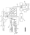
- FIG. 1 represents a functional block diagram for a device 10 constructed in accordance with the present invention.
- Device 10 represents one of the many forms of miniature personal communications devices which may be constructed in accordance with the present invention and which incorporates the antenna to be advantageously located in the attachment portion adapted for wearing the device on the body.
- One example for device 10 is a device capable of being worn on the wrist, such as a pager-watch, consisting of a wristband 12 and a housing or case 20, the configuration of which will be described in detail with FIG. 3.
- the tuning element, or capacitor 16 is shown to be contained in a section 18 of wristband 12 which provides concealment and protection, the function of which will become more obvious when the configuration of section 18 is described in detail in FIG. 3.
- a communications receiver 22 Within case 20, as shown in FIG. 1, is located a communications receiver 22, only a portion of which is shown to describe the present invention. It will be appreciated by those skilled in the art, that other well known circuit functions, such as a decoder and audio circuits, would also be part of a full description of communications receiver 22. Communications receiver 22 may be used to receive intelligence, such as commercial radio programming, or to provide other forms of communications, such as a selective call paging receiver, each of which is well known by persons skilled in the art. Within communications receiver 22 is shown a receiver portion 24 which is coupled to antenna 14 and tuning element 16 providing for reception of a transmitted RF carrier signal in a manner well known to one skilled in the art, and providing at the output an intermediate, or IF signal 25. The IF signal 25 is amplified by IF amplifier 26 to a level sufficient to drive a demodulator 28, coupled to the IF amplifier 26 output.
- the level of the signal provided at the output of the IF amplifier 26 is in limiting in the case of an FM communications receiver and such a limited signal cannot be used to monitor tuning of the antenna and receiver sections.
- a signal which varies linearly as the antenna and receiver sections are tuned is needed to monitor the tuning process, and is obtained by taking an intermediate tuning, or meter point, output 27 from the IF amplifier which has not been amplified as extensively as the signal at the output of the IF amplifier.
- case 20 houses an electronic timekeeping or watch circuit 30 consisting of a watch, or clock circuit 32 coupled to a display driver circuit 34 which drives a display 36.
- the operation of the electronic watch circuit 30 is well known to one skilled in the art. Switches are provided for controlling the watch functions, and are also provided for control of the receiver functions, but are not shown in FIG. 1 for the sake of clarity.
- case 20 also houses a tuning indicator circuit 38 consisting of a switch interface 40 used to select or enable tuning indicator circuit 38 operation when switch 74 (not shown in detail in FIG. 1) which is located in case 20 is actuated.
- the output of switch interface 40 couples to an electronic switch 42 which isolates tuning indicator circuit 38 from IF amplifier 26 when tuning indicator circuit 38 is not in use.
- the output of electronic switch 42 couples the meter point signal 27 to AC level detector circuit 44.
- a second output of switch interface 40 also couples to level detector circuit 44 controlling power supplied to level detector circuit 44 as will be described in detail later.
- Level detector circuit 44 provides a detection output signal 45 when meter point signal 27 exceeds a predetermined threshold voltage. Detection output signal 45 is coupled to display driver 34 and results in a predetermined area or segment of the display to illuminate, as would be the case with an LED display, or darken, as would be the case with an LCD display, thereby indicating the threshold voltage has been exceeded.
- FIG. 9B An example of one implementation of such a display is shown in FIG. 9B, to be described in detail later. The procedure for tuning antenna 14 using tuning indicator circuit 38, as described above, will be fully described later.
- FIG. 2 shows the preferred embodiment of antenna 14 constructed in the attachment portion of the device, such as a wristband, suitable for use with a miniature personal communications device.
- antenna 14 Only a brief description of antenna 14 will be given, as a detailed description of its construction and operation may be found in U.S. Patent No. 3,946,397 to Irwin, entitled "Inductor Antenna Arrangement with Integral Series Resonating Capacitors" which is assigned to the assignee of the present invention.
- antenna 14 is composed of a number of sections or links 56 fashioned using a ferromagnetic core 54, such as ferrite.
- a ferromagnetic core 54 such as ferrite.
- the links 56 are interconnected on a flexible substrate to form a multi-turn loop antenna which connects to tuning element 16.
- a protective cover such as silicon rubber or other suitable material, may be molded over the links 56 to provide environmental protection.
- Link 18 which protects and conceals tuning element 16 may be molded as part of the wristband.
- One output 55 from antenna 14 is coupled into case 20 to the input of RF amplifier 56 which, as will be appreciated by one skilled in the art, is usually the first stage of a communications receiver.
- the second output 57 is coupled into case 20 and provides the signal ground in a fashion also well known to one skilled in the art.
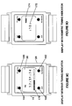
- FIG. 3 shows the construction of the preferred embodiment of the present invention suitable for wrist worn devices, such as pager-watches.
- Spring loaded pins 60 are used to secure wristband 12 to case 20 in a manner well known to one skilled in the art.
- interconnection of antenna 14 to receiver 22 which is contained on board 62 may be accomplished in a variety of ways, such as contacts located in the side of case 20 which allow electrical connection through case 20.
- Tuning element 16 is located in coupling link 18 which consists of a containment section 18A made from a rigid molded material, such as plastics as previously described, and a cover section 18B made from a formable material, such as sheet metal, prepared in a manner to provide a stylish appearance.
- Cover section 18B normally is closed, concealing tuning element 16. When required to tune antenna 14, cover section 18B may be pried open, exposing tuning element 16.
- a display 36 such as an LCD display, is connected to board 64 in a fashion well known to one skilled in the art.
- a cover 66 encloses the various components in case 20, and is secured by a number of screws 68, only one of which is illustrated.
- wristband 12 consists of two sections 12A and 12B.
- antenna 14 may be constructed into only one section of wristband 12, such as section 12A, although both sections could incorporate antenna elements if additional antenna sensitivity is required.
- FIG. 3 has shown that an antenna may be specifically constructed into a wristband which is normally used to provide attachment to the body, it should be clear that other body attachment devices, such as bracelets, necklaces, chains, and belts may be used for the dual purpose of body attachment and as part of an antenna system as previously described.
- Switch interface circuit 40 is shown to include a toggle flip flop 76, a current reference 88, and five transistors 78, 80, 82, 84, and 86.
- Current reference 88 together with transistor 84, which acts as a current mirror, provides a fixed output current at the collector of transistor 84 in a manner well known to one skilled in the art.
- the collector of transistor 84 connects to the base and collector of diode-connected transistor 80 and to the collector of transistor 78. Assuming transistor 78 to be switched off, the collector current of transistor 84 passes through diode-connected transistor 80.
- the base of transistor 82 is connected to the collector-base of diode-connected transistor 80, forming a current mirror with transistor 80.
- transistor 82 collector current is determined by the current delivered by transistor 84 passing through diode-connected transistor 80.
- the collector of transistor 82 is connected to the collector and base of diode-connected transistor 86, forming current mirrors with the PNP transistors located in the level detector 72, thus providing the bias for level detector operation.
- the operation of level detector 72 is best understood by referring to United States Patent Number 4,017,748 to Davis, entitled “Monolithic AC Level Detector" which is assigned to the assignee of the present invention.
- transistor 78 is switched off, power is provided to the level detector 72 which is then operational.
- a switch 74 is coupled to the input of toggle flip flop 76, alternately setting and resetting toggle flip flop 76 each time switch 74 is actuated.
- Q output terminal 90 is low.
- the Q output terminal 90 couples to the base of transistor 78, consequently when Q output terminal 90 is low, transistor 78 output will be high or off, activating level detector 72 as previously described.
- Q output terminal 90 goes high, turning transistor 78 on which sinks transistor 84 collector current, removing the bias to the current mirror formed by transistors 80 and 82, thereby turning off level detector 72.
- the Q-bar output terminal 92 of toggle flip flop 76 is connected to one of the control inputs of CMOS transmission gate 42. The other control input connects to Q output terminal 90.
- Q-bar output terminal 92 is high and Q output terminal 90 is low, switching CMOS transmission gate 42 into a low impedance state, thereby coupling the meter point signal 27 to the input of amplifier 70.
- Q-bar output terminal 92 is low and Q output terminal 90 is high, switching CMOS transmission gate 42 into a high impedance state, thereby isolating the meter point signal 27 from the input of amplifier 70 as previously described.
- Amplifier 70 is provided to boost meter point signal 27 by an amount, such as 30 dB, which is sufficient to allow operation of level detector 72, while maintaining meter point signal 27 to be in a linear range, such as around -30 dBm, when antenna 14 is being tuned.
- the output of amplifier 70 is coupled to the input of level detector 72, and when the input exceeds the threshold value to which level detector 72 is set, the output 45 of level detector 72 goes high.
- the output of level detector 72 is connected to display driver 34, causing an indication on display 36 that the threshold has been exceeded, and that antenna 14 is tuning.
- FIG. 5 shows the flowchart describing the antenna tuning procedure when a single tuning annunciator indicating a peak reading is provided, as described in the preferred embodiment of the present invention.
- the output of the RF generator is increased as shown at block 108, until tuning annunciator 168, to be described in detail later, illuminates, or otherwise indicates, as shown at block 110. If the tuning of antenna 14 is too far off to allow the RF generator output to be set at a reasonable level, such as from -80 to -100 dBm, tuning element 16 is rotated a fraction of a revolution to establish a closer tuning as shown at 112. When tuning annunciator 168 illuminates, as shown at block 110, either by increasing the output of the RF generator, or by increasing the output to a reasonable level and adjusting tuning element 16, the RF generator output is reduced until tuning annunciator 168 extinguishes, as shown at block 114.
- Tuning element 16 is then adjusted as shown at block 116 until tuning annunciator 168 illuminates as shown at block 118.
- the RF generator output is then reduced as shown at block 114, and the procedure described in blocks 114 through 118 is repeated as often as required until tuning annunciator 168 no longer illuminates as shown in block 118 after tuning element 16 is adjusted.
- tuning element 16 is then adjusted until tuning annunciator 168 extinguishes as shown in block 122. If tuning annunciator 168 fails to extinguish as shown at block 124, the procedure from block 108 through block 124 is repeated. If tuning annunciator 168 extinguishes, tuning element 16 is readjusted to the prior position at block 122 before final adjustment as shown at block 26, and the tuning procedure is completed.
- antenna 14 While only antenna 14 is tuned by the procedure just described, other stages within the receiver could just as easily be tuned, although the use of a single element annunciator and a peak threshold detector would slow the process due to the number of iterations of the procedure which would be required to achieve tuning.
- This problem is solved by an alternate embodiment of the present invention which provides a more rapid procedure and also allows antenna 14 to be tuned without physical entry into case 20 as in the case of the preferred embodiment of the present invention.
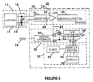
- FIG. 6 shows an alternate embodiment of the present invention.
- the difference between the embodiment described in FIG. 1 and that shown in FIG. 6 is in the level detecting circuit of tuning indicator circuit 38.
- FIG. 6 uses a multiple-level peak detector circuit 46 having multiple outputs 47 for driving the display.
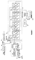
- the multiple-level peak detector circuit 46 may be better understood with reference now directed to FIG. 7 which shows the details of multiple-level peak detector circuit 46.
- the multiple-level peak detector circuit 46 is constructed of four individual peak detector circuits previously described in FIG. 4.
- Each of the individual peak detector circuits 72, 94, 96 and 98 are set to different threshold levels, such as a 2 dB difference between detectors 72 and 94, a 1 dB difference between detectors 94 and 96 and a 2 dB difference between detectors 96 and 98.
- the results of tuning are visually displayed on a multi-segment tuning annunciator 170 to be described in greater detail later.
- Operation of the individual peak detector circuits shown in FIG. 7 is exactly as previously decribed, except that each peak detector circuit has a slightly different peak threshold voltage.
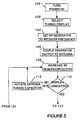
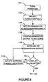
- FIG. 8 shows a flowchart of the tuning procedure suitable for use with the multi-level peak detector circuit 46 described in FIG. 7.
- Power to the device is turned on as shown at block 130.
- Antenna tuning is selected by actuating tuning selector switch 74 as shown at block 132.
- the RF generator is set to the receiver frequency of the device to be tuned, as shown at block 134, and the output of the RF generator is coupled to the antenna of the device as shown at block 132.
- the output of the RF generator is increased until tuning annunciator 170 illuminates, or otherwise indicates, as shown at block 140.
- tuning element 16 is adjusted, and the procedures of blocks 138 and 140 are repeated until tuning annunciator 170 illuminates as shown at block 140.
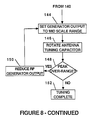
- the generator output is increased until two of the four segments are illuminated as shown at block 144, thus setting the RF generator to the midpoint of the tuning annunciator 170.
- Tuning element 16 is rotated and the results of tuning are noted on tuning annunciator 170.
- tuning annunciator 170 If all four segments of the tuning annunciator 170 are illuminated, indicating an over-range condition, the output of the RF generator is reduced, as shown at block 150, and the procedure of blocks 144 through 148 are repeated. If tuning element 16 can be adjusted so as to show a peak between the second and third annunciator segments, tuning is complete as shown at block 152.
- FIGS. 9A through 9D show pictorial diagrams of the preferred embodiment of the miniature personal communications device 10, which in this case shows a pager-watch display.
- Figure 9A shows a normal watch display 36 consisting of time and AM/PM graphics 158. It will be appreciated by one skilled in the art that other arrangements to display time and other information together with the tuning indication may be employed.
- the miniature personal communications device employs electronic controls 160 and 162, for controlling power to receiver 22 of the device. Such an arrangement allows the user of the device to turn off the receiver portion in the evening, if the user so desires, using "off" switch 160, and turning power on to the receiver portion of the device using "on/reset” switch 162.
- Two additional switches, "set” switch 164 and “display” switch 166 may be used to set and display time in a manner well known in the art for controlling the display of multifunction watch displays. Time information is displayed on display 36 in a well known fashion.
- a “tune” switch 74 is located on the side of watch case 20 (not shown) to control selection of the tuning feature previously described. “Tune” switch 74 is recessed to prevent accidental actuation while the pager-watch is being worn.
- FIG. 9B shows an example of a single segment annunciator 168 suitable for indicating tuning with a single threshold peak detector 44, as previously described.
- Tuning annunciator 168 is generally not visible until tuning has been selected and the threshold level of the level detector has been exceeded as previously described.
- FIG. 9C shows an example of a multi-segment tuning annunciator 170 which may be employed with a multiple-level peak detector 64, as previously described. Tuning annunciator 170 also is generally not visible until tuning has been selected and the threshold levels of the individual level detectors have been exceeded as previously described.
- FIG. 9D shows an another embodiment of the present invention wherein tuning annunciator 172 may actually employ some of the segments or digits normally used in the time display.
- tuning annunciator 172 when used with a more complex A/D converter circuit can provide substantially better resolution by displaying a number, such as "10" as shown as the midpoint of the level detector, and varying perhaps 10 steps around the midpoint, such as from 0 to 20.
- a number such as "10” as shown as the midpoint of the level detector
- 10 steps around the midpoint such as from 0 to 20.
- FIG. 9D shows an additional label 174, to indicate the tuning function is selected, as also shown in FIG. 9D.
- Other methods, such as flashing of the annunciator could also be employed to achieve the same result.
- the usefulness of the single digit annunciator shown in FIG. 9B may be enhanced, if the display driver is able to work with multiple inputs, and control such things as the contrast of the displayed segment. As tuning becomes closer, the contrast might increase, or if the display is allowed to flash when detuned, the display flashing might reduce in frequency or become steady when tuning has been achieved. Use of displays which would provide a digital graphic equivalence of a multiple level display similar to that provided by an analog meter would also be suitable as well.
- FIG. 10 shows in detail the setup used to tune the antenna of the miniature personal communications device, such as a pager-watch.
- the device is positioned on the body as would normally be worn, and secured in place.
- a small antenna 162 provided to deliver an unmodulated carrier signal from RF generator 160, would be located near antenna 14, being secured in place on the users wrist by means such as a velcro strap, while the tuning is being completed in the case of a pager-watch.
- a modulated signal could have also been used for tuning, such as normally occurring on a busy communications or paging channel, without effecting the outcome of the tuning.
- tuning element 16 is exposed by opening the cover to compartment 18 concealing tuning element 16 during normal wear. After tuning is completed, the cover is closed, and tuning antenna 162 is removed from the wrist.
Landscapes
- Details Of Aerials (AREA)
- Mobile Radio Communication Systems (AREA)
- Structure Of Receivers (AREA)
- Input Circuits Of Receivers And Coupling Of Receivers And Audio Equipment (AREA)
- Channel Selection Circuits, Automatic Tuning Circuits (AREA)
- Circuits Of Receivers In General (AREA)
- Variable-Direction Aerials And Aerial Arrays (AREA)
Claims (10)
- Tragbares Kommunikationsgerät (10) mit einem Empfänger (24) zum Empfangen gesendeter Signale und einer Antennenabstimmvorrichtung. Das Gerät umfaßt:
Anbringungseinrichtung (12) zum Anpassen des zu tragenden Geräts am Körper, wobei die Anbringungseinrichtung (12) eine Antenneneinrichtung (14) zum Auffangen gesendeter Signale enthält,
gekennzeichnet durch:
Antennenabstimmeinrichtung (16), verbunden mit der Antenneneinrichtung, zum Abstimmen der Antenneneinrichtung (14), und
Einrichtung zum Verbergen (18) der Antennenabstimmeinrichtung (16), wenn ein Abstimmen der Antenneneinrichtung (14) nicht erforderlich ist;
Empfängereinrichtung (20), ansprechend auf die Antenneneinrichtung (14), zum Empfangen der gesendeten Signale, wobei die Empfängereinrichtung (20) ein Abstimmsignal als Reaktion auf die Antennenabstimmeinrichtung (16), die eingestellt wird, wenn die gesendeten Signale empfangen werden, ableitet; und
Abstimmanzeigeeinrichtung (30, 38), ansprechend auf die Abstimmsignale, zum Bereitstellen einer Abstimmanzeige entsprechend den Absimmsignalen. - Tragbares Kommunikationsgerät (10) nach Anspruch 1, worin die Anbringungseinrichtung ein Handgelenkband (12) ist.
- Tragbares Kommunikationsgerät (10) nach Anspruch 2, worin das Handgelenkband (12) mit der Antenneneinrichtung (14), der Antennenabstimmeinrichtung (16) und der Einrichtung zum Verbergen (18) von dem Gerät (10) entfernt werden können.
- Tragbares Kommunikationsgerät (10) nach Anspruch 2, worin die Abstimmanzeigeeinrichtung (30, 38) weiter umfaßt:
Wahlschaltereinrichtung (40, 42), verbunden mit der Empfängereinrichtung (22), zum Steuern der Auswahl der Abstimmsignale;
Verstärkereinrichtung (70), verbunden mit der Wahlschaltereinrichtung (42), zum Verstärken der Abstimmsignale;
Anzeigeeinrichtung (34, 36); und
Abstimmdetektoreinrichtung (44 oder 46), verbunden mit der Verstärkereinrichtung (70), zum Ermitteln der Größe der verstärkten Abstimmsignale, wobei die Abstimmdetektoreinrichtung (30, 38) weiter mit der Anzeigeinrichtung (34, 36) zum Bereitstellen einer der Größe der Abstimmsignale entsprechenden Anzeige verbunden ist. - Tragbares Kommunikationsgerät (10) nach Anspruch 4, worin die Anzeigeeinrichtung (34, 36) sichtbar ist.
- Tragbares Kommunikationsgerät (10) nach Anspruch 5, worin die sichtbare Anzeigeeinrichtung (34, 36) ein Display (36) ist.
- Tragbares Kommunikationsgerät (10) nach Anspruch 6, worin das Display (36) eine graphische Anzeige entsprechend der Größe der Abstimmsignale bereitstellt.
- Tragbares Kommunikationsgerät (10) nach Anspruch 6, worin das Display (36) eine numerische Anzeige entsprechend der Größe der Abstimmsignale bereitstellt.
- Tragbares Kommunikationsgerät (10) nach Anspruch 4, worin die Wahlschaltereinrichtung (40, 42) weiter die Stromverorgung der Abstimmdetektoreinrichtung (44 oder 46) steuert.
- Tragbares Kommunikationsgerät (10) nach Anspruch 9, worin die Wahlschaltereinrichtung weiter umfaßt:
Schaltereinrichtung (74);
Signaltrenneinrichtung (42), verbunden mit der Empfängereinrichtung (22) und mit der Abstimmdetektoreinrichtung (44 oder 46), zum Steuern der Lieferung von Abstimmsignalen; und
Halteeinrichtung (76), ansprechend auf die Schaltereinrichtung (74) und verbunden mit der Signaltrenneinrichtung (42), zum Bewirken der Auswahl der Abstimmsignale und zum Steuern der Stromversorgung der Abstimmdetektoreinrichtung (44 oder 46).
Priority Applications (1)
| Application Number | Priority Date | Filing Date | Title |
|---|---|---|---|
| AT87901775T ATE88836T1 (de) | 1987-01-02 | 1987-01-02 | Geraet zur abstimmung einer antenne fuer personenkommunikationsanlagen. |
Applications Claiming Priority (1)
| Application Number | Priority Date | Filing Date | Title |
|---|---|---|---|
| PCT/US1987/000001 WO1988005213A1 (en) | 1987-01-02 | 1987-01-02 | Antenna tuning apparatus for personal communications devices |
Publications (2)
| Publication Number | Publication Date |
|---|---|
| EP0341239A1 EP0341239A1 (de) | 1989-11-15 |
| EP0341239B1 true EP0341239B1 (de) | 1993-04-28 |
Family
ID=22202233
Family Applications (1)
| Application Number | Title | Priority Date | Filing Date |
|---|---|---|---|
| EP87901775A Expired - Lifetime EP0341239B1 (de) | 1987-01-02 | 1987-01-02 | Gerät zur abstimmung einer antenne für personenkommunikationsanlagen |
Country Status (7)
| Country | Link |
|---|---|
| US (1) | US4817196A (de) |
| EP (1) | EP0341239B1 (de) |
| KR (1) | KR890700930A (de) |
| AT (1) | ATE88836T1 (de) |
| CA (1) | CA1288862C (de) |
| DE (1) | DE3785675T2 (de) |
| WO (1) | WO1988005213A1 (de) |
Families Citing this family (43)
| Publication number | Priority date | Publication date | Assignee | Title |
|---|---|---|---|---|
| US5052049A (en) * | 1987-10-20 | 1991-09-24 | Telefind Corporation | Paging receiver with continuously tunable antenna |
| US4851830A (en) * | 1987-10-20 | 1989-07-25 | Telefind Corp. | Paging receiver with continuously tunable antenna |
| US5012235A (en) * | 1987-10-20 | 1991-04-30 | Telefind Corporation | Paging receiver with continuously tunable antenna and RF amplifier |
| US5530453A (en) * | 1988-03-23 | 1996-06-25 | Seiko Epson Corporation | Wrist carried wireless instrument |
| US5265265A (en) * | 1990-02-09 | 1993-11-23 | Seiko Epson Corporation | Wristwatch radio communication device having an improved noise shielding structure |
| US5225846A (en) * | 1988-03-23 | 1993-07-06 | Seiko Epson Corporation | Wrist carried wireless instrument |
| JPH0777324B2 (ja) * | 1988-03-23 | 1995-08-16 | セイコーエプソン株式会社 | 腕装着型無線機 |
| US5280646A (en) * | 1988-03-23 | 1994-01-18 | Seiko Epson Corporation | Paging device with structure for removing static electricity |
| GB2220778B (en) * | 1988-07-11 | 1992-03-25 | Automated Security | Vehicle security |
| US5243356A (en) * | 1988-08-05 | 1993-09-07 | Seiko Epson Corporation | Antenna circuit and wrist radio instrument |
| US5136719A (en) * | 1988-12-05 | 1992-08-04 | Seiko Corp. | Automatic antenna tubing method and apparatus |
| WO1990011653A1 (en) * | 1989-03-28 | 1990-10-04 | Telefind Corporation | Paging receiver with continuously tunable antenna and rf amplifier |
| US4977614A (en) * | 1989-10-23 | 1990-12-11 | Motorola, Inc. | Wristband with loop antenna |
| US5134724A (en) * | 1990-05-08 | 1992-07-28 | Seiko Corp. | Wrist band for wrist-mounted radio with an uninsulated buckle |
| US5134418A (en) * | 1990-06-04 | 1992-07-28 | Motorola, Inc. | Apparatus for sensing the integrity of a wristband antenna |
| US5189431A (en) * | 1990-10-22 | 1993-02-23 | Motorola, Imc. | Removable antenna coupling on a wrist watch pager |
| US5206639A (en) * | 1990-10-25 | 1993-04-27 | Timex Corporation | Single antenna dual frequency transponder |
| US5263183A (en) * | 1991-04-30 | 1993-11-16 | Seiko Corp. | Radio antenna tuning circuit |
| US5280645A (en) * | 1991-05-24 | 1994-01-18 | Motorola, Inc. | Adjustable wristband loop antenna |
| US5265272A (en) * | 1991-08-12 | 1993-11-23 | Motorola, Inc. | Modular wrist band antenna |
| US5589840A (en) * | 1991-11-05 | 1996-12-31 | Seiko Epson Corporation | Wrist-type wireless instrument and antenna apparatus |
| KR930703716A (ko) * | 1991-11-05 | 1993-11-30 | 스스무 아이자와 | 무선기용 안테나 장치 |
| USD352666S (en) | 1992-05-21 | 1994-11-22 | Williams Alvin M | Combined wristwatch and pager |
| US5410749A (en) * | 1992-12-09 | 1995-04-25 | Motorola, Inc. | Radio communication device having a microstrip antenna with integral receiver systems |
| EP0616384B1 (de) * | 1993-03-17 | 2000-05-31 | Seiko Epson Corporation | Antenne und diese enthaltendes Gerät |
| US5539414A (en) * | 1993-09-02 | 1996-07-23 | Inmarsat | Folded dipole microstrip antenna |
| JP3417083B2 (ja) * | 1994-10-04 | 2003-06-16 | セイコーエプソン株式会社 | 携帯用無線機 |
| US5625891A (en) * | 1994-11-28 | 1997-04-29 | Tucker; Dominic | Enclosure for tuning paging receivers |
| US5659325A (en) * | 1994-12-02 | 1997-08-19 | Harris Corporation | Low impedance loop antenna and drive circuitry |
| US7058372B1 (en) | 2002-11-01 | 2006-06-06 | Integration Associates Inc. | Method and apparatus for automatic tuning of a resonant loop antenna |
| US7190933B2 (en) | 2002-11-01 | 2007-03-13 | Intergration Associates Inc. | Method and apparatus for automatic tuning of a resonant loop antenna in a transceiver circuit |
| DE10302550B3 (de) * | 2003-01-22 | 2004-08-12 | Forschungszentrum Karlsruhe Gmbh | Gürtelspule als Sende-/Empfangsantenne in einer Transpondereinrichtung |
| US7406003B2 (en) * | 2003-05-29 | 2008-07-29 | Timex Group B.V. | Multifunctional timepiece module with application specific printed circuit boards |
| US10575376B2 (en) | 2004-02-25 | 2020-02-25 | Lynk Labs, Inc. | AC light emitting diode and AC LED drive methods and apparatus |
| US10499465B2 (en) | 2004-02-25 | 2019-12-03 | Lynk Labs, Inc. | High frequency multi-voltage and multi-brightness LED lighting devices and systems and methods of using same |
| US8073548B2 (en) * | 2004-08-24 | 2011-12-06 | Sensors For Medicine And Science, Inc. | Wristband or other type of band having an adjustable antenna for use with a sensor reader |
| US7548211B2 (en) * | 2006-03-30 | 2009-06-16 | Phonak Ag | Wireless audio signal receiver device for a hearing instrument |
| GB0616927D0 (en) * | 2006-08-26 | 2006-10-04 | Qinetiq Ltd | Reader apparatus |
| US12279345B2 (en) | 2009-12-28 | 2025-04-15 | Lynk Labs, Inc. | Light emitting diode and LED drive apparatus |
| TW201304272A (zh) * | 2011-07-15 | 2013-01-16 | Wistron Neweb Corp | 隨身電子裝置之天線結構及隨身無線電子裝置 |
| CN104038176A (zh) * | 2014-06-16 | 2014-09-10 | 信维创科通信技术(北京)有限公司 | 一种可穿戴设备及其天线自适应阻抗匹配系统 |
| KR102595113B1 (ko) * | 2016-05-02 | 2023-10-30 | 삼성전자주식회사 | 안테나를 포함하는 전자 장치 |
| US10615489B2 (en) * | 2016-06-08 | 2020-04-07 | Futurewei Technologies, Inc. | Wearable article apparatus and method with multiple antennas |
Family Cites Families (11)
| Publication number | Priority date | Publication date | Assignee | Title |
|---|---|---|---|---|
| US2255897A (en) * | 1937-12-24 | 1941-09-16 | Rebori | Means for radio communication |
| US3526838A (en) * | 1967-12-20 | 1970-09-01 | Heath Co | Tuning indicator system for fm receiver |
| US3736591A (en) * | 1970-10-30 | 1973-05-29 | Motorola Inc | Receiving antenna for miniature radio receiver |
| US4017748A (en) * | 1975-12-29 | 1977-04-12 | Motorola, Inc. | Monolithic AC level detector |
| JPS53101210A (en) * | 1977-02-16 | 1978-09-04 | Matsushita Electric Ind Co Ltd | Signal level display unit |
| US4419770A (en) * | 1981-05-02 | 1983-12-06 | Sony Corporation | Wrist AM radio receiver |
| JPS57190429A (en) * | 1981-05-18 | 1982-11-24 | Nec Corp | Portable radio receiver |
| EP0100639A3 (de) * | 1982-08-02 | 1986-03-05 | Shaye Communications Limited | Antennenkopplungsvorrichtung |
| CA1223346A (en) * | 1984-08-14 | 1987-06-23 | Siltronics Ltd. | Antenna |
| EP0184606A3 (de) * | 1984-12-05 | 1988-03-30 | A.T. & E. LABORATORIES, INC. | Aufruf-Uhrsystem mit Zeitfensterkommunikation |
| US4713808A (en) * | 1985-11-27 | 1987-12-15 | A T & E Corporation | Watch pager system and communication protocol |
-
1987
- 1987-01-02 EP EP87901775A patent/EP0341239B1/de not_active Expired - Lifetime
- 1987-01-02 DE DE8787901775T patent/DE3785675T2/de not_active Expired - Lifetime
- 1987-01-02 WO PCT/US1987/000001 patent/WO1988005213A1/en not_active Ceased
- 1987-01-02 AT AT87901775T patent/ATE88836T1/de not_active IP Right Cessation
- 1987-01-02 US US07/074,426 patent/US4817196A/en not_active Expired - Fee Related
- 1987-12-31 CA CA000555701A patent/CA1288862C/en not_active Expired - Lifetime
-
1988
- 1988-09-02 KR KR1019880701060A patent/KR890700930A/ko active Granted
Also Published As
| Publication number | Publication date |
|---|---|
| EP0341239A1 (de) | 1989-11-15 |
| WO1988005213A1 (en) | 1988-07-14 |
| DE3785675D1 (de) | 1993-06-03 |
| US4817196A (en) | 1989-03-28 |
| CA1288862C (en) | 1991-09-10 |
| ATE88836T1 (de) | 1993-05-15 |
| KR890700930A (ko) | 1989-04-28 |
| DE3785675T2 (de) | 1993-08-19 |
Similar Documents
| Publication | Publication Date | Title |
|---|---|---|
| EP0341239B1 (de) | Gerät zur abstimmung einer antenne für personenkommunikationsanlagen | |
| US4862516A (en) | System for automatically tuning the antenna of a miniature portable communications device | |
| JPH01503265A (ja) | 小型パーソナル通信機用アンテナ・チューニング装置 | |
| EP0366875B1 (de) | Armbanduhr mit Funksprechanlage | |
| US4063410A (en) | Digital watch including a signal transmitter | |
| EP0741433B1 (de) | Antennenstruktur für eine Uhr | |
| EP0616384B1 (de) | Antenne und diese enthaltendes Gerät | |
| US5926144A (en) | Wearable electronic device and antenna therefor | |
| US6047163A (en) | Miniature radio apparatus having loop antenna including human body | |
| GB2201266A (en) | A radio paging watch | |
| KR20020026359A (ko) | 시계 기능을 갖춘 휴대유닛용 자동 시간-설정 시스템 | |
| HK1039181A1 (en) | Wristwatch provided with an antenna | |
| EP0100639A2 (de) | Antennenkopplungsvorrichtung | |
| EP0741434B1 (de) | Antennenstruktur für eine Uhr | |
| AU7034087A (en) | Antenna tuning apparatus for personal communications devices | |
| KR930010831B1 (ko) | 안테나 튜닝 장치 | |
| US7397437B2 (en) | Band coupling structure incorporating conductive wires | |
| JP3700339B2 (ja) | アンテナ付き電子機器 | |
| GB2171821A (en) | The combination of an electronic wrist-watch and a two- way radio communication system | |
| US5923265A (en) | Portable receiver comprising a manually actuable control device | |
| AU6898387A (en) | Automatic antenna tuning system for portable communication devices | |
| JPH08211169A (ja) | 腕時計型無線選択呼び出し受信機 | |
| JPH0787541A (ja) | 腕時計型無線受信機 | |
| JPS5489671A (en) | Switch structure of electronic wristwatch | |
| TH27200B (th) | วัตถุที่สามารถหิ้วถือไปมาได้โดยเฉพาะนาฬิกาข้อมือ และรวมไปถึงมอดูลอิเล็กทรอนิกส์ที่สามารถเลือกให้ทำงานได้หลายๆอย่าง |
Legal Events
| Date | Code | Title | Description |
|---|---|---|---|
| PUAI | Public reference made under article 153(3) epc to a published international application that has entered the european phase |
Free format text: ORIGINAL CODE: 0009012 |
|
| 17P | Request for examination filed |
Effective date: 19890605 |
|
| AK | Designated contracting states |
Kind code of ref document: A1 Designated state(s): AT BE CH DE FR GB IT LI LU NL SE |
|
| 17Q | First examination report despatched |
Effective date: 19910802 |
|
| RIN1 | Information on inventor provided before grant (corrected) |
Inventor name: IRWIN, JAMES, STUART Inventor name: MACNAK, PHILIP, PAUL |
|
| GRAA | (expected) grant |
Free format text: ORIGINAL CODE: 0009210 |
|
| AK | Designated contracting states |
Kind code of ref document: B1 Designated state(s): AT BE CH DE FR GB IT LI LU NL SE |
|
| PG25 | Lapsed in a contracting state [announced via postgrant information from national office to epo] |
Ref country code: SE Effective date: 19930428 |
|
| REF | Corresponds to: |
Ref document number: 88836 Country of ref document: AT Date of ref document: 19930515 Kind code of ref document: T |
|
| ITF | It: translation for a ep patent filed | ||
| REF | Corresponds to: |
Ref document number: 3785675 Country of ref document: DE Date of ref document: 19930603 |
|
| ET | Fr: translation filed | ||
| ITTA | It: last paid annual fee | ||
| PG25 | Lapsed in a contracting state [announced via postgrant information from national office to epo] |
Ref country code: LU Free format text: LAPSE BECAUSE OF NON-PAYMENT OF DUE FEES Effective date: 19940131 |
|
| PLBE | No opposition filed within time limit |
Free format text: ORIGINAL CODE: 0009261 |
|
| STAA | Information on the status of an ep patent application or granted ep patent |
Free format text: STATUS: NO OPPOSITION FILED WITHIN TIME LIMIT |
|
| 26N | No opposition filed | ||
| PGFP | Annual fee paid to national office [announced via postgrant information from national office to epo] |
Ref country code: CH Payment date: 19950127 Year of fee payment: 9 |
|
| PGFP | Annual fee paid to national office [announced via postgrant information from national office to epo] |
Ref country code: NL Payment date: 19950131 Year of fee payment: 9 |
|
| PGFP | Annual fee paid to national office [announced via postgrant information from national office to epo] |
Ref country code: BE Payment date: 19950210 Year of fee payment: 9 |
|
| PGFP | Annual fee paid to national office [announced via postgrant information from national office to epo] |
Ref country code: GB Payment date: 19951204 Year of fee payment: 10 |
|
| PGFP | Annual fee paid to national office [announced via postgrant information from national office to epo] |
Ref country code: FR Payment date: 19960129 Year of fee payment: 10 |
|
| PGFP | Annual fee paid to national office [announced via postgrant information from national office to epo] |
Ref country code: DE Payment date: 19960130 Year of fee payment: 10 |
|
| PG25 | Lapsed in a contracting state [announced via postgrant information from national office to epo] |
Ref country code: LI Effective date: 19960131 Ref country code: CH Effective date: 19960131 Ref country code: BE Effective date: 19960131 |
|
| BERE | Be: lapsed |
Owner name: MOTOROLA INC. Effective date: 19960131 |
|
| PG25 | Lapsed in a contracting state [announced via postgrant information from national office to epo] |
Ref country code: NL Effective date: 19960801 |
|
| REG | Reference to a national code |
Ref country code: CH Ref legal event code: PL |
|
| NLV4 | Nl: lapsed or anulled due to non-payment of the annual fee |
Effective date: 19960801 |
|
| PG25 | Lapsed in a contracting state [announced via postgrant information from national office to epo] |
Ref country code: GB Effective date: 19970102 |
|
| PGFP | Annual fee paid to national office [announced via postgrant information from national office to epo] |
Ref country code: AT Payment date: 19970728 Year of fee payment: 11 |
|
| GBPC | Gb: european patent ceased through non-payment of renewal fee |
Effective date: 19970102 |
|
| PG25 | Lapsed in a contracting state [announced via postgrant information from national office to epo] |
Ref country code: FR Effective date: 19970930 |
|
| PG25 | Lapsed in a contracting state [announced via postgrant information from national office to epo] |
Ref country code: DE Effective date: 19971001 |
|
| REG | Reference to a national code |
Ref country code: FR Ref legal event code: ST |
|
| PG25 | Lapsed in a contracting state [announced via postgrant information from national office to epo] |
Ref country code: AT Free format text: LAPSE BECAUSE OF NON-PAYMENT OF DUE FEES Effective date: 19980102 |
|
| PG25 | Lapsed in a contracting state [announced via postgrant information from national office to epo] |
Ref country code: IT Free format text: LAPSE BECAUSE OF NON-PAYMENT OF DUE FEES Effective date: 20050102 |
|
| P01 | Opt-out of the competence of the unified patent court (upc) registered |
Effective date: 20230520 |