EP0706025B1 - Patronenhülse für eine Treibladung - Google Patents
Patronenhülse für eine Treibladung Download PDFInfo
- Publication number
- EP0706025B1 EP0706025B1 EP95402234A EP95402234A EP0706025B1 EP 0706025 B1 EP0706025 B1 EP 0706025B1 EP 95402234 A EP95402234 A EP 95402234A EP 95402234 A EP95402234 A EP 95402234A EP 0706025 B1 EP0706025 B1 EP 0706025B1
- Authority
- EP
- European Patent Office
- Prior art keywords
- case
- envelope
- propellant charge
- support
- charge according
- Prior art date
- Legal status (The legal status is an assumption and is not a legal conclusion. Google has not performed a legal analysis and makes no representation as to the accuracy of the status listed.)
- Expired - Lifetime
Links
- 230000001141 propulsive effect Effects 0.000 title 1
- 239000003380 propellant Substances 0.000 claims description 39
- 239000000463 material Substances 0.000 claims description 19
- 239000007866 anti-wear additive Substances 0.000 claims description 14
- 239000007789 gas Substances 0.000 claims description 4
- 230000000284 resting effect Effects 0.000 claims description 2
- 239000000567 combustion gas Substances 0.000 description 10
- 239000013589 supplement Substances 0.000 description 9
- 238000002485 combustion reaction Methods 0.000 description 6
- 239000000020 Nitrocellulose Substances 0.000 description 4
- GWEVSGVZZGPLCZ-UHFFFAOYSA-N Titan oxide Chemical compound O=[Ti]=O GWEVSGVZZGPLCZ-UHFFFAOYSA-N 0.000 description 4
- 229920001220 nitrocellulos Polymers 0.000 description 4
- 238000009434 installation Methods 0.000 description 3
- 238000004026 adhesive bonding Methods 0.000 description 2
- 238000001035 drying Methods 0.000 description 2
- 239000000446 fuel Substances 0.000 description 2
- 238000000034 method Methods 0.000 description 2
- 239000000203 mixture Substances 0.000 description 2
- 239000000123 paper Substances 0.000 description 2
- 239000000843 powder Substances 0.000 description 2
- 239000004408 titanium dioxide Substances 0.000 description 2
- 230000005540 biological transmission Effects 0.000 description 1
- 239000000470 constituent Substances 0.000 description 1
- 238000000151 deposition Methods 0.000 description 1
- 230000000694 effects Effects 0.000 description 1
- 238000010304 firing Methods 0.000 description 1
- 238000013467 fragmentation Methods 0.000 description 1
- 238000006062 fragmentation reaction Methods 0.000 description 1
- 229910052751 metal Inorganic materials 0.000 description 1
- 239000002184 metal Substances 0.000 description 1
- 238000007747 plating Methods 0.000 description 1
- 230000000630 rising effect Effects 0.000 description 1
- 238000007493 shaping process Methods 0.000 description 1
- 238000004804 winding Methods 0.000 description 1
Images


Classifications
-
- F—MECHANICAL ENGINEERING; LIGHTING; HEATING; WEAPONS; BLASTING
- F42—AMMUNITION; BLASTING
- F42B—EXPLOSIVE CHARGES, e.g. FOR BLASTING, FIREWORKS, AMMUNITION
- F42B5/00—Cartridge ammunition, e.g. separately-loaded propellant charges
- F42B5/38—Separately-loaded propellant charges, e.g. cartridge bags
-
- F—MECHANICAL ENGINEERING; LIGHTING; HEATING; WEAPONS; BLASTING
- F42—AMMUNITION; BLASTING
- F42B—EXPLOSIVE CHARGES, e.g. FOR BLASTING, FIREWORKS, AMMUNITION
- F42B5/00—Cartridge ammunition, e.g. separately-loaded propellant charges
- F42B5/02—Cartridges, i.e. cases with charge and missile
- F42B5/18—Caseless ammunition; Cartridges having combustible cases
- F42B5/188—Manufacturing processes therefor
-
- F—MECHANICAL ENGINEERING; LIGHTING; HEATING; WEAPONS; BLASTING
- F42—AMMUNITION; BLASTING
- F42B—EXPLOSIVE CHARGES, e.g. FOR BLASTING, FIREWORKS, AMMUNITION
- F42B5/00—Cartridge ammunition, e.g. separately-loaded propellant charges
- F42B5/02—Cartridges, i.e. cases with charge and missile
- F42B5/24—Cartridges, i.e. cases with charge and missile for cleaning; for cooling; for lubricating ; for wear reducing
-
- Y—GENERAL TAGGING OF NEW TECHNOLOGICAL DEVELOPMENTS; GENERAL TAGGING OF CROSS-SECTIONAL TECHNOLOGIES SPANNING OVER SEVERAL SECTIONS OF THE IPC; TECHNICAL SUBJECTS COVERED BY FORMER USPC CROSS-REFERENCE ART COLLECTIONS [XRACs] AND DIGESTS
- Y10—TECHNICAL SUBJECTS COVERED BY FORMER USPC
- Y10S—TECHNICAL SUBJECTS COVERED BY FORMER USPC CROSS-REFERENCE ART COLLECTIONS [XRACs] AND DIGESTS
- Y10S102/00—Ammunition and explosives
- Y10S102/70—Combustilbe cartridge
-
- Y—GENERAL TAGGING OF NEW TECHNOLOGICAL DEVELOPMENTS; GENERAL TAGGING OF CROSS-SECTIONAL TECHNOLOGIES SPANNING OVER SEVERAL SECTIONS OF THE IPC; TECHNICAL SUBJECTS COVERED BY FORMER USPC CROSS-REFERENCE ART COLLECTIONS [XRACs] AND DIGESTS
- Y10—TECHNICAL SUBJECTS COVERED BY FORMER USPC
- Y10S—TECHNICAL SUBJECTS COVERED BY FORMER USPC CROSS-REFERENCE ART COLLECTIONS [XRACs] AND DIGESTS
- Y10S102/00—Ammunition and explosives
- Y10S102/704—Coolants
Definitions
- the technical field of the invention is that of cases made of combustible material. intended to contain a propellant charge, in particular for artillery ammunition heavy gauge.
- the patent US3204558 thus describes a metal cartridge munition comprising an anti wear supplement placed on its internal envelope or on a sheet wrapped around the propellant charge.
- Patent EP0410075 which is taken as the basis of the preamble of the claim 1 of this application, provides for depositing a mixture of wax and titanium dioxide on the inner surface of the cylindrical shell of a module or a combustible case.
- the case according to the invention thus makes it possible to ensure complete combustion of the constituent material of its envelope while optimally distributing the back-up anti-wear. This provides effective protection of the weapon tubes, even when the amount of propellant charge is small.
- the invention also allows rapid and inexpensive installation of a anti-wear back-up in a combustible case.
- the subject of the invention is therefore a combustible case comprising an envelope substantially cylindrical made of a combustible material and intended to receive a propellant charge, and comprising an anti-wear supplement, case characterized in that the anti-wear back-up is arranged on at least one reception area of at least one support made of combustible material and in that the case includes means ensuring the positioning of the support relative to the envelope of the case of such so that after mounting there is at least one free space between the internal surface of the envelope and the anti-wear back-up, space intended to allow the passage of gases from combustion between the envelope and the anti-wear back-up.
- the support is a form sheet substantially cylindrical bearing against at least one radial stop which allows to ensure a free space between the internal surface of the envelope and the anti-wear back-up.
- the radial stop consists of a part of the propellant charge
- the radial stop is constituted at least by a cover closing the case cover
- the radial stop comprises at least one ring in combustible material integral with the sheet or envelope.
- the anti-wear back-up reception area (s) can be formed by through openings made on a cylindrical wall of the support, the openings being partially filled by the anti-wear back-up so that a free space is provided between the anti-wear back-up and the internal surface of the envelope.
- the cylindrical wall of the support can constitute an extension of at least one envelope closure cover.
- the support consists of a sheet corrugated, the anti-wear back-up reception area consisting of at least one internal and / or external hollow.
- the reception area may consist of at least one internal recess, the external hollow remaining empty.
- the reception area may consist of at least one external recess, the internal hollow remaining empty.
- the corrugated sheet bears against the surface internal envelope.
- the cylindrical wall of the support can constitute a extension of at least one closure cover the envelope.
- the support consists of a corrugated sheet, the reception area anti-wear back-up consisting of at least one internal and / or external hollow.
- the reception area can consist of at least an internal hollow, the external hollows remaining empty.
- the reception area can consist of at least an external recess, the internal recesses remaining empty.
- the corrugated sheet is resting against the inner surface of the envelope.
- a modular element of propellant artillery charge is a holster 1 which comprises a cylindrical tubular casing 2 made of combustible material such as cardboard loaded with nitrocellulose and closed at each end with a cover 3 also made of combustible material.
- the two covers 3 are identical and have each a bottom 4 secured to a cylindrical rim 5. They are made integral with the envelope 2 by bonding to level of their cylindrical edge 5.
- Each cover has a cylindrical collar axial 6 on which a cylindrical duct is positioned 7 also made of combustible material and fixed to each cover 3 by gluing at the flanges 6.
- the conduit 7 is intended to receive a device ignition of known type not shown, formed for example by a stack of rings of compressed black powder.
- the case 1 is intended to receive a propellant charge 21 of known type, for example in the form of strands 8.
- the propellant charge is set up before gluing the second cover.
- the case 1 includes, inside the load propellant, a substantially cylindrical support 12 produced made of combustible material and covered on its internal surface by an anti-wear supplement 10.
- the support 12 is a sheet 9 produced for example from cardboard loaded with nitrocellulose.
- the sheet has a thickness of about 0.3 to 0.5 mm, which allows it to support the installation of a anti-wear top layer and gives it such rigidity that it can be kept inside the case without need to be attached to another element.
- Anti-wear back-up is carried out, in a known manner, by a mixture of wax and titanium dioxide in a proportion of 50% for each component.
- the sheet 9 of cylindrical tubular shape is placed inside the propellant charge and away from the casing 2 of the case 1.
- the propellant charge serves as radial stop at sheet 9 and provides free space 13 between the envelope and the top-up 10.
- Figure 2 shows a cross section along the plane AA of figure 1.
- the anti-wear back-up is placed on the inner surface of the tubular sheet 9. It could indifferently be placed on the external surface of the leaf.
- Such a configuration makes it possible to maintain the top-up anti-wear at a distance from the wall which facilitates complete combustion of the wall 2 of combustible material, anti-wear back-up which does not block gas from combustion generated by the propellant charge.
- the extra is itself attacked by the following propellant charge two substantially opposite sides and so it's better distributed over the wall of the barrel of the weapon.
- the sheet-top unit After drying and hardening, the sheet-top unit is placed in the module before the installation of the propellant charge and second cover.
- the anti-wear back-up reception area may consist of only one or more portions of the leaf surface, allowing clear one or more passages to the combustion gases from the propellant charge through the sheet.
- the support can consist of one or more cylindrical sectors held in place by the load propellant.
- the case according to the invention can also be a combustible case for a propellant charge of a tank ammunition.
- FIG. 3 represents a case according to a second mode for carrying out the invention.
- the case 1 which is composed of the envelope 2 closed by two covers 3 has a support 12 also consisting of a sheet 9 of combustible material which receives an anti-wear supplement 10.
- the sheet 9 has a cylindrical tubular shape and it is manufactured like the sheet previously described.
- the anti-wear back-up is kept away from wall 2 by at least a radial stop which is formed by the flanges cylindrical 5 covers 3 against which comes support the support 12.
- a free space 13 is thus provided between the envelope and the top-up and allows the gases to combustion of propellant charge (e.g. powder in bulk not shown), after having burned the covers, to attack the anti-wear supplement 10 by two faces substantially opposite while ensuring combustion complete of envelope 2.
- propellant charge e.g. powder in bulk not shown
- FIG. 4 shows a variant of this second mode for carrying out the invention.
- the envelope 2 of the case 1 comprises, on its internal face and substantially at mid-height between the two flanges 5, a ring 23 made of material fuel and made integral with the envelope for example by collage.
- the support 12 is in support, by through the sheet 9, against the ring 23 which also plays a role of radial stop.
- Such a configuration makes it possible to avoid a possible plating of the support 12 against the envelope 2 during the pressure increase in the combustion gases of the load propellant.
- this stop radial in the form of a portion of rings. he is also conceivable to provide several rings and / or portions of rings integral with the sheet 9 or the envelope 2.
- the sheet 9 can be made of a fragile or brittle material when rising combustion gas pressure. The fragmentation of the sheet will lead to the extra one, which allows create additional passages in which will engage the combustion gases to attack envelope and top up.
- the sheet can be made for example in a combustible and brittle material of nitrofilm type.
- Figure 5 shows in section a third mode of realization of a case according to the invention.
- the covers 3 comprise a cylindrical rim 5 of a length substantially equal to half a length of the case 1 so that the edges of the two covers are substantially in contact One against the other.
- the covers 3 have on their edge 5 through openings 14, here 8 in number.
- the openings 14 are partially filled with anti-wear supplement 10.
- the duct 7 is then glued to the covers 3, then we place the envelope 2 on the covers making slide it on these.
- One or more orifices, not shown, will be made on the bottoms 4 covers 3 so that loading can be introduced propellant in the module.
- the holes will be closed after filling with a sheet of paper or a cap appropriate.
- a substantially cylindrical support fitted with openings can be placed against the surface internal of the case between two covers having a reduced length rim.
- Support could also be attached to a single cover, the second cover then having only a reduced length rim.
- the number and size of the openings can be variables and some openings can remain without anti-wear back-up.
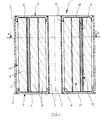
- Figure 6 shows in section a fourth mode of realization of a case according to the invention.
- the support 12 is a sheet 9 of corrugated shape made of material combustible.
- the sheet 9 receives in the internal recesses 15 of its anti-wear additives 10, whose surface external 17 is substantially flush with the top 18 of the ripples.
- the external hollows 16 of the undulations of the sheet 9 remain empty and provide several free spaces 13 between the support and the envelope 2, spaces which affect the shape longitudinal chimneys.
- the sheet 9 is here in abutment against the edges cylindrical 5 of the covers, as shown in the figure 7 and thus the sheet is not in abutment against the surface internal of the case and the free spaces 13 comprise also a tubular volume 22 corresponding to the thickness of the edges 5.
- the support can be in abutment against the inner surface of the envelope 2, which allows passage direct combustion gases via chimneys 13.
- sheet 9 receives anti-wear supplement 10 in the external recesses 16 of the ripples.
- Sheet 9 is here in direct contact with the inner surface of the envelope 2 by the external vertices 19 of its undulations.
- the external surface 20 of the top-up anti-wear is set back from the external vertices 19 undulations thus creating several free spaces 13 in the form of chimneys between envelope 2 and the top-up anti-wear.
- the hollows 15 which are not covered with extra, therefore that burn very quickly, and the free spaces 13 allow the rapid passage of combustion gases from the propellant charge towards the envelope 2.
- the envelope will burn without difficulty and the anti-wear additive will assaulted on several distinct sides.
Landscapes
- Engineering & Computer Science (AREA)
- General Engineering & Computer Science (AREA)
- Manufacturing & Machinery (AREA)
- Filling Or Discharging Of Gas Storage Vessels (AREA)
- Containers And Packaging Bodies Having A Special Means To Remove Contents (AREA)
- Laminated Bodies (AREA)
Claims (11)
- Brennbare Hülse (1) bestehend aus einem in etwa zylindrischen Mantel (2) bestehend aus brennbarem Werkstoff, der eine Treibladung (21) aufnehmen soll und einen abnutzungsmindernden Zusatz (10) umfaßt, gekennzeichnet dadurch , daß der abnutzungsmindernde Zusatz auf mindestens eine Aufnahmezone mindestens eines Trägers (12) bestehend aus brennbarem Werkstoff aufgebracht wird und dadurch, daß die Hülse Mittel umfaßt, die die Positionierung des Trägers (12) in bezug auf den Mantel (2) der Hülse so gewährleisten, daß nach der Montage mindestens ein freier Raum (13) zwischen der Innenoberfläche des Mantels (2) und dem abnutzungsmindernden Zusatz (10) besteht, der dazu bestimmt ist, die Passage der Verbrennungsgase zwischen dem Mantel (2) und dem abnutzungsmindernden Zusatz (10) zu erlauben.
- Hülse (1) für eine Treibladung gemäß dem Anspruch 1, gekennzeichnet dadurch, daß der Träger (12) ein Blatt (9) in etwa zylindrischer Form ist, der gegen mindestens einen radialen Anschlag aufliegt, der es ermöglicht, zwischen der Innenoberfläche des Mantels (2) und dem abnutzungsmindernden Zusatz (10) einen freien Raum (13) sicherzustellen.
- Hülse (1) für eine Treibladung gemäß dem Anspruch 2, gekennzeichnet dadurch, daß der radiale Anschlag aus einem Teil der Treibladung (21) besteht.
- Hülse (1) für eine Treibladung gemäß dem Anspruch 2, gekennzeichnet dadurch, daß der radiale Anschlag aus mindestens einem Deckel (3) besteht, der den Mantel (2) der Hülse (1) schließt.
- Hülse (1) für eine Treibladung gemäß einem beliebigen der Ansprüche 2 oder 4, gekennzeichnet dadurch, daß der radiale Anschlag mindestens einen Ring aus brennbarem Werkstoff umfaßt, der mit dem Blatt (9) oder dem Mantel (2) fest verbunden ist.
- Hülse (1) für eine Treibladung gemäß dem Anspruch 1, gekennzeichnet dadurch, daß die Zone oder Zonen zur Aufnahme des abnutzungsmindernden Zusatzes aus durchgehenden Öffnungen (14) bestehen, die in einer zylindrischen Wand des Trägers (12) angeordnet sind, wobei die Öffnung oder Öffnungen teilweise mit abnutzungsminderndem Zusatz (10) so gefüllt sind, daß mindestens ein freier Raum (13) zwischen dem abnutzungsmindernden Zusatz (10) und der Innenoberfläche des Mantels (2) eingerichtet wird.
- Hülse (1) für eine Treibladung gemäß dem Anspruch 6, gekennzeichnet dadurch, daß die zylindrische Wand des Trägers (12) eine Verlängerung mindestens eines der Verschlußdeckel (3) des Mantels (2) bildet.
- Hülse (1) für eine Treibladung gemäß dem Anspruch 1, gekennzeichnet dadurch, daß der Träger (12) aus einem welligen Blatt (9) besteht, wobei die Zone für die Aufnahmen des abnutzungsmindernden Zusatzes (10) aus mindestens einer internen und / oder externen Vertiefung besteht.
- Hülse (1) für eine Treibladung gemäß dem Anspruch 8, gekennzeichnet dadurch, daß die Aufnahmezone aus mindestens einer internen Vertiefung (15) besteht, wobei die externen Vertiefungen (16) leer bleiben.
- Hülse (1) für eine Treibladung gemäß dem Anspruch 8, gekennzeichnet dadurch, daß die Aufnahmezone aus mindestens einer externen Vertiefung (16) besteht, wobei die internen Vertiefungen (15) leer bleiben.
- Hülse (1) für eine Treibladung gemäß einem beliebigen der Ansprüche 8 bis 10, gekennzeichnet dadurch, daß das gewellte Blatt (9) gegen die Innenoberfläche des Mantels (2) aufliegt.
Applications Claiming Priority (2)
| Application Number | Priority Date | Filing Date | Title |
|---|---|---|---|
| FR9411937 | 1994-10-06 | ||
| FR9411937A FR2725510B1 (fr) | 1994-10-06 | 1994-10-06 | Etui pour un chargement propulsif |
Publications (2)
| Publication Number | Publication Date |
|---|---|
| EP0706025A1 EP0706025A1 (de) | 1996-04-10 |
| EP0706025B1 true EP0706025B1 (de) | 1999-10-13 |
Family
ID=9467617
Family Applications (1)
| Application Number | Title | Priority Date | Filing Date |
|---|---|---|---|
| EP95402234A Expired - Lifetime EP0706025B1 (de) | 1994-10-06 | 1995-10-06 | Patronenhülse für eine Treibladung |
Country Status (4)
| Country | Link |
|---|---|
| US (1) | US5672842A (de) |
| EP (1) | EP0706025B1 (de) |
| DE (1) | DE69512737T2 (de) |
| FR (1) | FR2725510B1 (de) |
Cited By (1)
| Publication number | Priority date | Publication date | Assignee | Title |
|---|---|---|---|---|
| RU2631518C2 (ru) * | 2016-03-09 | 2017-09-25 | Российская Федерация, от имени которой выступает Министерство обороны Российской Федерации | Модуль модульного метательного заряда к артиллерийским орудиям безгильзового заряжания (варианты) |
Families Citing this family (18)
| Publication number | Priority date | Publication date | Assignee | Title |
|---|---|---|---|---|
| US5747723A (en) * | 1996-11-26 | 1998-05-05 | The United States Of America As Represented By The Secretary Of The Army | Modular artillery charge system |
| FR2763392B1 (fr) * | 1997-05-15 | 1999-06-11 | Giat Ind Sa | Boitier pour charge propulsive |
| DE19917633C1 (de) * | 1999-04-19 | 2000-11-23 | Fraunhofer Ges Forschung | Treibladungsanordnung für Rohrwaffen oder ballistische Antriebe |
| US6343552B1 (en) | 2000-06-06 | 2002-02-05 | Alliant Techsystems Inc. | Solvent application system |
| US6360666B1 (en) | 2000-06-06 | 2002-03-26 | Alliant Techsystems Inc. | Alignment fixture |
| US6382104B1 (en) * | 2000-11-07 | 2002-05-07 | The United States Of America As Represented By The Secretary Of The Navy | Two-piece base pad igniter bag |
| NO20005773A (no) * | 2000-11-14 | 2002-04-15 | Nammo Raufoss As | Pyroteknisk ladningsstruktur |
| US6854996B2 (en) * | 2002-12-20 | 2005-02-15 | Tyco Electronics Corporation | Electrical connectors and methods for using the same |
| FR2875413B1 (fr) * | 2004-09-21 | 2008-01-11 | Snpe Materiaux Energetiques Sa | Dispositif d'injection sans aiguille fonctionnant avec deux matieres energetiques concentriques |
| US7546804B1 (en) * | 2006-10-10 | 2009-06-16 | The United States Of America As Represented By The Secretary Of The Army | Artillery charge with laser ignition |
| ATE514918T1 (de) * | 2007-02-23 | 2011-07-15 | Clearspark Llc | Abschussvorrichtung für feuerwerksgeschossen |
| JP5978928B2 (ja) * | 2012-11-02 | 2016-08-24 | 日油株式会社 | ガス発生材、並びにこれを使用した発射装薬及び弾薬 |
| US9625242B1 (en) * | 2015-02-12 | 2017-04-18 | The United States Of America As Represented By The Secretary Of The Army | Igniter for modular artillery charge system |
| US10107607B1 (en) | 2017-04-04 | 2018-10-23 | The United States Of America As Represented By The Secretary Of The Army | Radio frequency igniter |
| RU2662537C1 (ru) * | 2017-10-05 | 2018-07-26 | Федеральное казенное предприятие "Государственный научно-исследовательский институт химических продуктов" (ФКП "ГосНИИХП") | Жесткий сгорающий картуз для метательных зарядов минометных выстрелов |
| US10969206B1 (en) | 2018-11-29 | 2021-04-06 | U.S. Government As Represented By The Secretary Of The Army | Radio frequency antenna for use in the confines of a breech |
| US11041701B1 (en) * | 2019-07-03 | 2021-06-22 | The United States Of America As Represented By The Secretary Of The Army | Combustible munition case with cell cavities |
| FR3115869B1 (fr) * | 2020-11-04 | 2022-11-11 | Eurenco France | Procede de fabrication d'un boitier renfermant un chargement pyrotechnique |
Family Cites Families (13)
| Publication number | Priority date | Publication date | Assignee | Title |
|---|---|---|---|---|
| DE35348C (de) * | A. ST. LYMAN in Brooklyn, V. St. ..An | Neuerung an Patronen für Geschütze | ||
| FR437228A (fr) * | 1911-12-06 | 1912-04-16 | Marie Louis Raoul Saladin | Poudre de guerre et de chasse, et son système de fabrication |
| US1187779A (en) * | 1914-10-02 | 1916-06-20 | Wilbur Miller C | Ammunition. |
| FR692609A (fr) * | 1929-04-05 | 1930-11-07 | Anciens Ets Skoda | Procédé pour la mise de feu des charges et disposition de ces dernières dans les douilles de cartouches |
| US3204558A (en) * | 1959-08-14 | 1965-09-07 | Wegematic Corp | Wear reduction additives |
| US3527168A (en) * | 1960-12-05 | 1970-09-08 | Minnesota Mining & Mfg | Solid propellant grain containing metal macrocapsules of fuel and oxidizer |
| US3658008A (en) * | 1970-04-17 | 1972-04-25 | Dow Corning | Integrated round with combustible cartridge |
| US3734020A (en) * | 1971-10-01 | 1973-05-22 | Us Army | Igniter for propelling charges |
| US4098193A (en) * | 1976-09-08 | 1978-07-04 | The United States Of America As Represented By The Secretary Of The Army | Wear and corrosion reducing additive for gun propellants |
| SE461094B (sv) * | 1987-08-21 | 1990-01-08 | Nobel Kemi Ab | Saett att framstaella drivkrutsladdningar samt i enlighet daermed framstaella laddningar |
| DE3924986A1 (de) * | 1989-07-28 | 1991-01-31 | Rheinmetall Gmbh | Treibladungsbehaelter |
| DE69111944T2 (de) * | 1990-08-30 | 1996-04-18 | Olin Corp | Hülsenloses einheitsliches Ammunitionsladungsmodul. |
| DE4204318A1 (de) * | 1991-02-15 | 1992-08-20 | Dynamit Nobel Ag | Treibladungsmodul |
-
1994
- 1994-10-06 FR FR9411937A patent/FR2725510B1/fr not_active Expired - Fee Related
-
1995
- 1995-10-06 EP EP95402234A patent/EP0706025B1/de not_active Expired - Lifetime
- 1995-10-06 DE DE69512737T patent/DE69512737T2/de not_active Expired - Fee Related
-
1997
- 1997-01-09 US US08/781,139 patent/US5672842A/en not_active Expired - Fee Related
Cited By (1)
| Publication number | Priority date | Publication date | Assignee | Title |
|---|---|---|---|---|
| RU2631518C2 (ru) * | 2016-03-09 | 2017-09-25 | Российская Федерация, от имени которой выступает Министерство обороны Российской Федерации | Модуль модульного метательного заряда к артиллерийским орудиям безгильзового заряжания (варианты) |
Also Published As
| Publication number | Publication date |
|---|---|
| DE69512737D1 (de) | 1999-11-18 |
| US5672842A (en) | 1997-09-30 |
| FR2725510B1 (fr) | 1997-01-24 |
| EP0706025A1 (de) | 1996-04-10 |
| DE69512737T2 (de) | 2000-03-02 |
| FR2725510A1 (fr) | 1996-04-12 |
Similar Documents
| Publication | Publication Date | Title |
|---|---|---|
| EP0706025B1 (de) | Patronenhülse für eine Treibladung | |
| EP0640205B1 (de) | Hülse für teleskopische munitionen | |
| EP0646762A1 (de) | Verbrennbare Hulsenteile für Artilleriegeschosse, Verfahren zu deren Herstellung und Verwendung derselben | |
| FR2679993A1 (fr) | Munition, en particulier du type telescope. | |
| FR2720495A1 (fr) | Dispositif permettant de solidariser deux conteneurs et conteneur associé à un tel dispositif. | |
| EP0499500B1 (de) | Behälter, vorgesehen mit elektrischen Verbindungsmitteln | |
| CA1331315C (fr) | Chargement propulsif pour munition comportant un projectile empenne ainsi que son procede de realisation | |
| EP1181498B1 (de) | Anzündrohr für artilleriemunition | |
| EP0660070A1 (de) | Treibladungsbehälter und Verfahren zu seiner Herstellung | |
| FR2725781A1 (fr) | Materiau d'allumage pour charge propulsive et systeme d'allumage ou tube allumeur mettant en oeuvre un tel materiau | |
| FR2728675A1 (fr) | Cartouche avec une douille et un projectile a fleche | |
| EP0065435B1 (de) | Granate für den zivilen Einsatz mit schwacher Zündladung | |
| EP0754927B1 (de) | System zum Zünden einer Treibladung insbesondere für Feldgeschütze und sein Herstellungsverfahren | |
| FR2713328A1 (fr) | Conteneur pour charge propulsive pouvant être rendu solidaire d'un autre conteneur. | |
| EP0757223B1 (de) | Behälter für Munition für Artillerie mit selbstverbrennender Patronenhülse | |
| EP0674150B1 (de) | Munition mit Anti-Verschleissmittel | |
| EP1586852A1 (de) | Hülsenlose Munition und Herstellungsverfahren dafür | |
| WO2022096795A1 (fr) | Procede de fabrication d'un boitier renfermant un chargement pyrotechnique | |
| FR2849179A1 (fr) | Munition sans douille et procede de montage d'une telle munition | |
| FR2497335A1 (fr) | Gargousse pour munitions d'artillerie | |
| BE625469A (de) | ||
| FR2683626A1 (fr) | Grenade generatrice de gaz reversible. | |
| FR2710975A1 (fr) | Elément de munition d'artillerie et munition obtenue par assemblage d'une pluralité de tels éléments. | |
| FR2741143A1 (fr) | Dispositif de maintien d'un revetement d'une charge generatrice de noyau | |
| FR3050521A1 (fr) | Sac de poudre propulsive, charge propulsive d'artillerie incorporant un tel sac et procede de fabrication |
Legal Events
| Date | Code | Title | Description |
|---|---|---|---|
| PUAI | Public reference made under article 153(3) epc to a published international application that has entered the european phase |
Free format text: ORIGINAL CODE: 0009012 |
|
| AK | Designated contracting states |
Kind code of ref document: A1 Designated state(s): DE GB IT SE |
|
| 17P | Request for examination filed |
Effective date: 19960603 |
|
| 17Q | First examination report despatched |
Effective date: 19980323 |
|
| GRAG | Despatch of communication of intention to grant |
Free format text: ORIGINAL CODE: EPIDOS AGRA |
|
| GRAG | Despatch of communication of intention to grant |
Free format text: ORIGINAL CODE: EPIDOS AGRA |
|
| GRAH | Despatch of communication of intention to grant a patent |
Free format text: ORIGINAL CODE: EPIDOS IGRA |
|
| GRAH | Despatch of communication of intention to grant a patent |
Free format text: ORIGINAL CODE: EPIDOS IGRA |
|
| GRAA | (expected) grant |
Free format text: ORIGINAL CODE: 0009210 |
|
| AK | Designated contracting states |
Kind code of ref document: B1 Designated state(s): DE GB IT SE |
|
| PG25 | Lapsed in a contracting state [announced via postgrant information from national office to epo] |
Ref country code: GB Free format text: LAPSE BECAUSE OF FAILURE TO SUBMIT A TRANSLATION OF THE DESCRIPTION OR TO PAY THE FEE WITHIN THE PRESCRIBED TIME-LIMIT Effective date: 19991013 |
|
| ITF | It: translation for a ep patent filed | ||
| REF | Corresponds to: |
Ref document number: 69512737 Country of ref document: DE Date of ref document: 19991118 |
|
| GBV | Gb: ep patent (uk) treated as always having been void in accordance with gb section 77(7)/1977 [no translation filed] |
Effective date: 19991013 |
|
| PLBE | No opposition filed within time limit |
Free format text: ORIGINAL CODE: 0009261 |
|
| STAA | Information on the status of an ep patent application or granted ep patent |
Free format text: STATUS: NO OPPOSITION FILED WITHIN TIME LIMIT |
|
| 26N | No opposition filed | ||
| PG25 | Lapsed in a contracting state [announced via postgrant information from national office to epo] |
Ref country code: IT Free format text: LAPSE BECAUSE OF NON-PAYMENT OF DUE FEES;WARNING: LAPSES OF ITALIAN PATENTS WITH EFFECTIVE DATE BEFORE 2007 MAY HAVE OCCURRED AT ANY TIME BEFORE 2007. THE CORRECT EFFECTIVE DATE MAY BE DIFFERENT FROM THE ONE RECORDED. Effective date: 20051006 |
|
| PGFP | Annual fee paid to national office [announced via postgrant information from national office to epo] |
Ref country code: DE Payment date: 20060928 Year of fee payment: 12 |
|
| PG25 | Lapsed in a contracting state [announced via postgrant information from national office to epo] |
Ref country code: DE Free format text: LAPSE BECAUSE OF NON-PAYMENT OF DUE FEES Effective date: 20080501 |
|
| PGFP | Annual fee paid to national office [announced via postgrant information from national office to epo] |
Ref country code: SE Payment date: 20120924 Year of fee payment: 18 |
|
| REG | Reference to a national code |
Ref country code: SE Ref legal event code: EUG |
|
| PG25 | Lapsed in a contracting state [announced via postgrant information from national office to epo] |
Ref country code: SE Free format text: LAPSE BECAUSE OF NON-PAYMENT OF DUE FEES Effective date: 20131007 |